Download to read offline
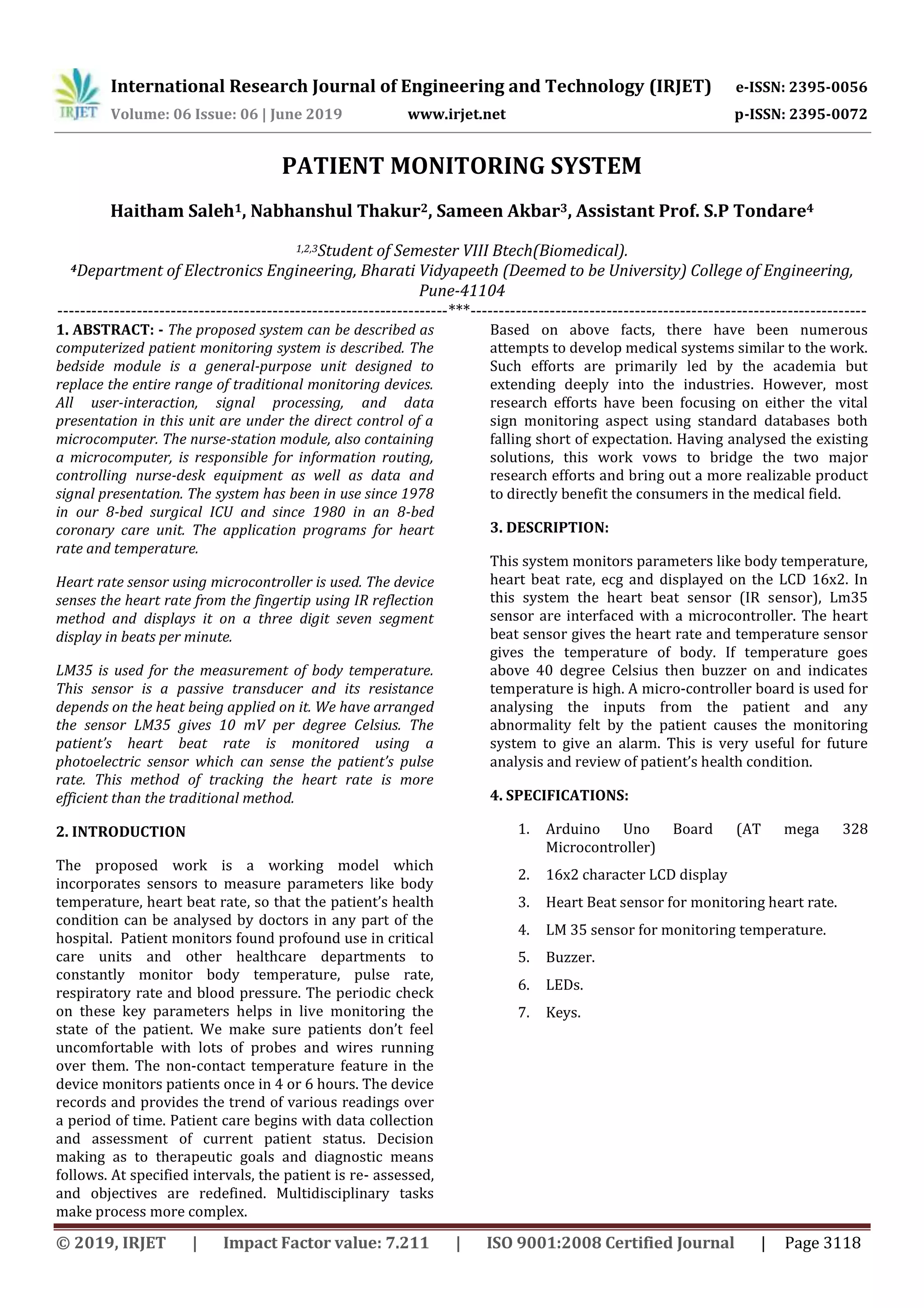


The document describes a patient monitoring system that uses sensors to measure a patient's heart rate, body temperature, and other vital signs. An Arduino microcontroller is used to collect data from sensors like a heart rate sensor and LM35 temperature sensor, and display the readings on an LCD screen. The system is intended to help doctors monitor patients' health conditions remotely by recording vital signs over time.