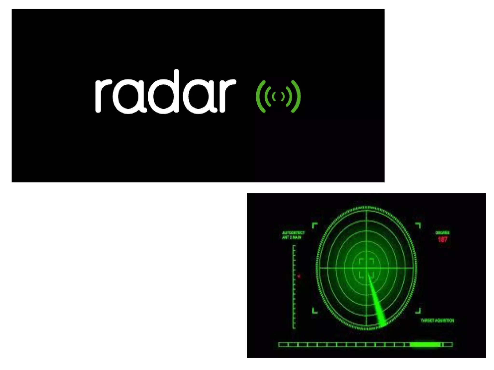
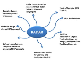
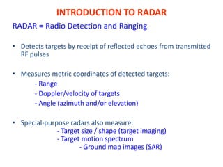
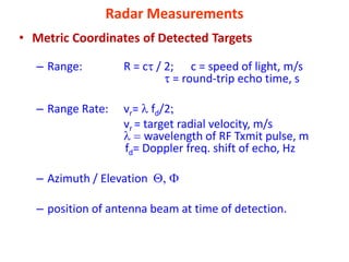
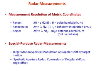
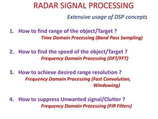
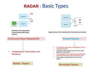
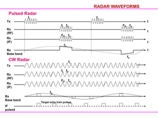
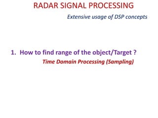
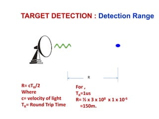
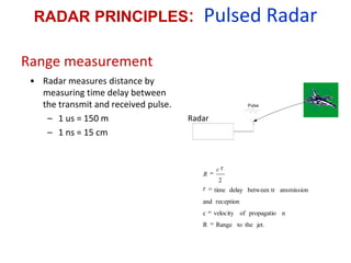
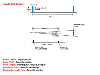
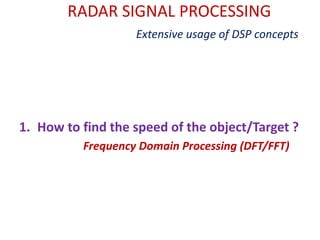
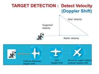
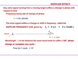
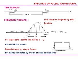
SlideShare a Scribd company logo
1 of 36
Download to read offline
RADAR
Electro Magnetic (EM)
SENSOR
Uses Radio Waves
Used for
Detection of Objects
Finding Position, vel
Imaging of Objects/Gnd
Tracking objects etc
Complex System
Multidisciplinary
knowledge
Hardware design
follows COTS appraoch
Software development
comprises extensive
amount of DSP concepts
Acts as a Motivation
for Learning and
Understanding DSP
Radar concepts can be
used in ROBOT Radar,
SONAR ,Ultrasonic
ranging etc
INTRODUCTION TO RADAR
RADAR = Radio Detection and Ranging
• Detects targets by receipt of reflected echoes from transmitted
RF pulses
• Measures metric coordinates of detected targets:
- Range
- Doppler/velocity of targets
- Angle (azimuth and/or elevation)
• Special-purpose radars also measure:
- Target size / shape (target imaging)
- Target motion spectrum
- Ground map images (SAR)
RADAR : Working Principle
Radar Measurements
• Metric Coordinates of Detected Targets
– Range: R = c / 2; c = speed of light, m/s
= round-trip echo time, s
– Range Rate: vr= fd/2
vr = target radial velocity, m/s
wavelength of RF Txmit pulse, m
fd= Doppler freq. shift of echo, Hz
– Azimuth / Elevation
– position of antenna beam at time of detection.
Radar Measurements
• Measurement Resolution of Metric Coordinates
– Range: R = c /(2 B) ; B = pulse bandwidth, Hz
– Range Rate: vr= /(2 Tc); Tc = coherent integration tim, s
– Angle: = /D ;D = antenna aperture, m
( in radians
• Special-Purpose Radar Measurements
– Target Motion Spectra; Modulation of Doppler shift by target
motion
– Synthetic Aperture Radar; Conversion of Doppler shift to
angle offset
RADAR SIGNAL PROCESSING
Extensive usage of DSP concepts
1. How to find range of the object/Target ?
Time Domain Processing (Band Pass Sampling)
2. How to find the speed of the object/Target ?
Frequency Domain Processing (DFT/FFT)
3. How to achieve desired range resolution ?
Frequency Domain Processing (Fast Convolution,
Windowing)
4. How to suppress Unwanted signal/Clutter ?
Frequency Domain Processing (FIR Filters)
Radar On a Robot
Radar Basics
Band Designation Frequency range (MHz)
HF 3 - 30
VHF 30 - 300
UHF 300 - 1000
L 1000 - 2000
S 2000 - 4000
C 4000 - 8000
X 8000 - 12,000
Ku 12,000 - 18,000
Ka 27,000 - 40,000
mm 40 - 300GHz
RADAR FREQUECY BAND
Ultrasonic Ranging
RADAR : Basic Types
• Co-located transmitter and Receiver with a
sharing antenna
• A pulse is transmitted and then the radar
listens for the return
• The strength of the signal is proportional to
the target distance and its electrical size
• The range is calculated from the time
delay
Single antenna Time shared by the transmitter and receiver
CW Radar with independent
Transmitting and Receiving
antenna
Continuous Wave Radars(CW) Pulsed Radars
• Independent Transmitter and
Receiver
Bistatic Radars Monostatic Radars
RADAR WAVEFORMS
Pulsed Radar
Tx t
ft fd
ft
Rx
(RF)
FIF fd
t
Rx
(IF)
FIF fd
Rx
Base band
t
t
fd
fd
CW Radar
Tx
Rx
(RF)
Rx
(IF)
Rx
Base band
IF
pulsed
ft
ft
ft fd
FIF fd
fd
Target echo train pulses
RADAR SIGNAL PROCESSING
Extensive usage of DSP concepts
1. How to find range of the object/Target ?
Time Domain Processing (Sampling)
R= cTR/2
Where
c= velocity of light
TR= Round Trip Time
For ,
TR=1us
R= ½ x 3 x 108 x 1 x 10-6
=150m.
Radar
TARGET DETECTION : Detection Range
R
RADAR WAVEFORMS
 CW : Continuous Wave
 FMCW : Freq. Modulated Continuous Wave
 Pulsed
 Pulsed Coded
T = 1/PRF = PRI
Pulse Width :
Pulse Repetition Interval (PRI) : T
Pulse Repetition Frequency (PRF) : fr = 1/T
The PRF is chosen to meet the max. unambiguous Range desired :
Dist = Speed x Time
2 x Runamb max = C x T = C x 1/fr
fr ≤ C/ 2.R unamb max
t
Rmax proportional to [ PTG2 2 / (4 )3)Smin]
PT = Transmitted power
G = Gain of the antenna
= Wave length
= Target cross section
Smin = Minimum Detection signal
Rmax = [ PTAe2 /4 2 Smin] ¼
Ae = Antenna aperture
RADAR RANGE EQUATION
Range measurement
Radar
Radar
Pulse
Radar
jet.
the
to
Range
R
n
propagatio
of
velocity
c
reception
and
ansmission
between tr
delay
time
2
c
R
• Radar measures distance by
measuring time delay between
the transmit and received pulse.
– 1 us = 150 m
– 1 ns = 15 cm
RADAR PRINCIPLES: Pulsed Radar
 Radio Detection and Ranging (RADAR)
 Uses Electromagnetic wave
RADAR
Radar
R
R
Target
Tx t
TD
t
Distance : 2R
Speed : 3x 10⁸ m/s
R = TD * 3 x 10⁸
For 1 Km TD = 6.666 sec
1 sec delay = 150 m range
Power : Radar range Equation
Pulse Width : Range Resolution
Pulse Length : Unambiguous Range & Doppler
Number of Pulses : Doppler and Energy
Modulation inside Pulse : Range Resolution
How to Find Range?
Range (A/D) Sampling Process
x
pulse
(1/ f )
s
range / time
xmit xmit
pulse
xmit
pulse
target
echoes
pulse repetition interval (pri)
N A/D Sampling
Strobes
r
target
echoes
range / time
N / f
r s
fs = A/D Sampling rate
Maximum unambiguous Range, Run=cT/2
Target return
Target return
T
Time
Time
Ambiguous
Range
TARGET DETECTION : Maximum Range
Unambiguous
Range
RADAR SIGNAL PROCESSING
Extensive usage of DSP concepts
1. How to find the speed of the object/Target ?
Frequency Domain Processing (DFT/FFT)
Total Velocity
Radial Velocity
Tangential
Velocity
Produces Maximum
Doppler Shift
Zero
Doppler Shift
Part of the target’s velocity
produces doppler shift
TARGET DETECTION : Detect Velocity
(Doppler Shift)
Frequency being rate of change of phase:
f = 1/2 (d /dt)
The echo signal suffers a change or shift in frequency called the
DOPPLER FREQUENCY shift, given by : fd = 2 vr/ = 2 v. Cosθ/
DOPPLER EFFECT
Any echo signal coming from a moving target suffers a change in phase with
respect to time
Antenna
u
θ
vr
Vr = v. cosθ
Wavelength : is the distance the wave must travel to suffer a 360˚ phase
change or complete one cycle :
Time for 1 cycle = 1/f
SPECTRUM OF PULSED RADAR SIGNAL
TIME DOMAIN :
t
ft
ft
T = 1/ fr
FREQUENCY DOMAIN :
fr
2/
ft - 1/ ft ft + 1/
For target echo : central line will be ft fd
Each line has a spread :
Spread depend on several factors
but mainly dominated by inverse of antenna dwell time.
fr
f
Expanded view
Line spectrum weighted by SINC
function.
0
-PRF +PRF
Doppler
shift
fd
Echo spectral line
Unambiguous
doppler region
Unambiguous doppler
Transmit spectral line
Clutter echo
0
-PRF +PRF
Doppler
shift
fd
Ambiguous doppler
fa
TARGET DETECTION : Doppler Ambiguity
Graphical Analysis of Radar signal
Spectrum
How to Find Velocity?
PRF 1
(low)
PRF 2
(high)
repetitive
Line spectrum
repetitive
Time & Frequency Trade Off
Good for Range
Finding
Good for Velocity
Finding
1000 Pulses
2 Pulses
INTRODUCTION TO AIRBORNE RADAR
BY GEORGE W. STIMSON
SCITECH PUBLICATIONS
Reference
Introduction-to-Radar-Lecture-1-Material.pdf

More Related Content

Similar to Introduction-to-Radar-Lecture-1-Material.pdf

chandra shekhar_Unit 2 _Radar_ feb 4 2016
chandra shekhar_Unit 2 _Radar_ feb 4 2016chandra shekhar_Unit 2 _Radar_ feb 4 2016
chandra shekhar_Unit 2 _Radar_ feb 4 2016
CHANDRA SHEKHAR
 
Radar Principles & Systems.ppt
Radar Principles & Systems.pptRadar Principles & Systems.ppt
Radar Principles & Systems.ppt
mancangkul1
 
Subsystems of radar and signal processing
Subsystems of radar and signal processing Subsystems of radar and signal processing
Subsystems of radar and signal processing
Ronak Vyas
 

Similar to Introduction-to-Radar-Lecture-1-Material.pdf (20)

chandra shekhar_Unit 2 _Radar_ feb 4 2016
chandra shekhar_Unit 2 _Radar_ feb 4 2016chandra shekhar_Unit 2 _Radar_ feb 4 2016
chandra shekhar_Unit 2 _Radar_ feb 4 2016
 
Radar is a detection system that uses radio waves to determine the range, ang...
Radar is a detection system that uses radio waves to determine the range, ang...Radar is a detection system that uses radio waves to determine the range, ang...
Radar is a detection system that uses radio waves to determine the range, ang...
 
Radar
RadarRadar
Radar
 
Radar Systems- Unit- I : Basics of Radar
Radar Systems- Unit- I : Basics of Radar Radar Systems- Unit- I : Basics of Radar
Radar Systems- Unit- I : Basics of Radar
 
radar
radarradar
radar
 
Lecture03.ppt
Lecture03.pptLecture03.ppt
Lecture03.ppt
 
RADAR SYSTEMS
RADAR SYSTEMSRADAR SYSTEMS
RADAR SYSTEMS
 
Radar Principles & Systems.ppt
Radar Principles & Systems.pptRadar Principles & Systems.ppt
Radar Principles & Systems.ppt
 
Radar
RadarRadar
Radar
 
Principles of RADAR Systems
Principles of RADAR SystemsPrinciples of RADAR Systems
Principles of RADAR Systems
 
IARE_RS_PPT_0.pdf
IARE_RS_PPT_0.pdfIARE_RS_PPT_0.pdf
IARE_RS_PPT_0.pdf
 
Radar signal processing
Radar signal processingRadar signal processing
Radar signal processing
 
Radar fundamentals
Radar fundamentalsRadar fundamentals
Radar fundamentals
 
Radar Basics
Radar BasicsRadar Basics
Radar Basics
 
6Aesa7.ppt
6Aesa7.ppt6Aesa7.ppt
6Aesa7.ppt
 
Subsystems of radar and signal processing
Subsystems of radar and signal processing Subsystems of radar and signal processing
Subsystems of radar and signal processing
 
Introduction Radar signal processing.pdf
Introduction Radar signal processing.pdfIntroduction Radar signal processing.pdf
Introduction Radar signal processing.pdf
 
Fdp radar
Fdp radarFdp radar
Fdp radar
 
synthetic aperture radar
synthetic aperture radarsynthetic aperture radar
synthetic aperture radar
 
Radar
RadarRadar
Radar
 

Recently uploaded

Hospital management system project report.pdf
Hospital management system project report.pdfHospital management system project report.pdf
Hospital management system project report.pdf
Kamal Acharya
 
Query optimization and processing for advanced database systems
Query optimization and processing for advanced database systemsQuery optimization and processing for advanced database systems
Query optimization and processing for advanced database systems
meharikiros2
 
Introduction to Robotics in Mechanical Engineering.pptx
Introduction to Robotics in Mechanical Engineering.pptxIntroduction to Robotics in Mechanical Engineering.pptx
Introduction to Robotics in Mechanical Engineering.pptx
hublikarsn
 
scipt v1.pptxcxxxxxxxxxxxxxxxxxxxxxxxxxxxxxxxxxxxxxxxxxxxxxxxxxxxxxxxxxxxxxxx...
scipt v1.pptxcxxxxxxxxxxxxxxxxxxxxxxxxxxxxxxxxxxxxxxxxxxxxxxxxxxxxxxxxxxxxxxx...scipt v1.pptxcxxxxxxxxxxxxxxxxxxxxxxxxxxxxxxxxxxxxxxxxxxxxxxxxxxxxxxxxxxxxxxx...
scipt v1.pptxcxxxxxxxxxxxxxxxxxxxxxxxxxxxxxxxxxxxxxxxxxxxxxxxxxxxxxxxxxxxxxxx...
HenryBriggs2
 
Digital Communication Essentials: DPCM, DM, and ADM .pptx
Digital Communication Essentials: DPCM, DM, and ADM .pptxDigital Communication Essentials: DPCM, DM, and ADM .pptx
Digital Communication Essentials: DPCM, DM, and ADM .pptx
pritamlangde
 

Recently uploaded (20)

Linux Systems Programming: Inter Process Communication (IPC) using Pipes
Linux Systems Programming: Inter Process Communication (IPC) using PipesLinux Systems Programming: Inter Process Communication (IPC) using Pipes
Linux Systems Programming: Inter Process Communication (IPC) using Pipes
 
Hospital management system project report.pdf
Hospital management system project report.pdfHospital management system project report.pdf
Hospital management system project report.pdf
 
Query optimization and processing for advanced database systems
Query optimization and processing for advanced database systemsQuery optimization and processing for advanced database systems
Query optimization and processing for advanced database systems
 
Convergence of Robotics and Gen AI offers excellent opportunities for Entrepr...
Convergence of Robotics and Gen AI offers excellent opportunities for Entrepr...Convergence of Robotics and Gen AI offers excellent opportunities for Entrepr...
Convergence of Robotics and Gen AI offers excellent opportunities for Entrepr...
 
Online food ordering system project report.pdf
Online food ordering system project report.pdfOnline food ordering system project report.pdf
Online food ordering system project report.pdf
 
Computer Networks Basics of Network Devices
Computer Networks  Basics of Network DevicesComputer Networks  Basics of Network Devices
Computer Networks Basics of Network Devices
 
Ground Improvement Technique: Earth Reinforcement
Ground Improvement Technique: Earth ReinforcementGround Improvement Technique: Earth Reinforcement
Ground Improvement Technique: Earth Reinforcement
 
Introduction to Robotics in Mechanical Engineering.pptx
Introduction to Robotics in Mechanical Engineering.pptxIntroduction to Robotics in Mechanical Engineering.pptx
Introduction to Robotics in Mechanical Engineering.pptx
 
Theory of Time 2024 (Universal Theory for Everything)
Theory of Time 2024 (Universal Theory for Everything)Theory of Time 2024 (Universal Theory for Everything)
Theory of Time 2024 (Universal Theory for Everything)
 
Memory Interfacing of 8086 with DMA 8257
Memory Interfacing of 8086 with DMA 8257Memory Interfacing of 8086 with DMA 8257
Memory Interfacing of 8086 with DMA 8257
 
Hostel management system project report..pdf
Hostel management system project report..pdfHostel management system project report..pdf
Hostel management system project report..pdf
 
scipt v1.pptxcxxxxxxxxxxxxxxxxxxxxxxxxxxxxxxxxxxxxxxxxxxxxxxxxxxxxxxxxxxxxxxx...
scipt v1.pptxcxxxxxxxxxxxxxxxxxxxxxxxxxxxxxxxxxxxxxxxxxxxxxxxxxxxxxxxxxxxxxxx...scipt v1.pptxcxxxxxxxxxxxxxxxxxxxxxxxxxxxxxxxxxxxxxxxxxxxxxxxxxxxxxxxxxxxxxxx...
scipt v1.pptxcxxxxxxxxxxxxxxxxxxxxxxxxxxxxxxxxxxxxxxxxxxxxxxxxxxxxxxxxxxxxxxx...
 
8th International Conference on Soft Computing, Mathematics and Control (SMC ...
8th International Conference on Soft Computing, Mathematics and Control (SMC ...8th International Conference on Soft Computing, Mathematics and Control (SMC ...
8th International Conference on Soft Computing, Mathematics and Control (SMC ...
 
Design For Accessibility: Getting it right from the start
Design For Accessibility: Getting it right from the startDesign For Accessibility: Getting it right from the start
Design For Accessibility: Getting it right from the start
 
HOA1&2 - Module 3 - PREHISTORCI ARCHITECTURE OF KERALA.pptx
HOA1&2 - Module 3 - PREHISTORCI ARCHITECTURE OF KERALA.pptxHOA1&2 - Module 3 - PREHISTORCI ARCHITECTURE OF KERALA.pptx
HOA1&2 - Module 3 - PREHISTORCI ARCHITECTURE OF KERALA.pptx
 
Digital Communication Essentials: DPCM, DM, and ADM .pptx
Digital Communication Essentials: DPCM, DM, and ADM .pptxDigital Communication Essentials: DPCM, DM, and ADM .pptx
Digital Communication Essentials: DPCM, DM, and ADM .pptx
 
Introduction to Artificial Intelligence ( AI)
Introduction to Artificial Intelligence ( AI)Introduction to Artificial Intelligence ( AI)
Introduction to Artificial Intelligence ( AI)
 
Computer Graphics Introduction To Curves
Computer Graphics Introduction To CurvesComputer Graphics Introduction To Curves
Computer Graphics Introduction To Curves
 
HAND TOOLS USED AT ELECTRONICS WORK PRESENTED BY KOUSTAV SARKAR
HAND TOOLS USED AT ELECTRONICS WORK PRESENTED BY KOUSTAV SARKARHAND TOOLS USED AT ELECTRONICS WORK PRESENTED BY KOUSTAV SARKAR
HAND TOOLS USED AT ELECTRONICS WORK PRESENTED BY KOUSTAV SARKAR
 
Post office management system project ..pdf
Post office management system project ..pdfPost office management system project ..pdf
Post office management system project ..pdf
 

Introduction-to-Radar-Lecture-1-Material.pdf

  • 1.
  • 2. RADAR Electro Magnetic (EM) SENSOR Uses Radio Waves Used for Detection of Objects Finding Position, vel Imaging of Objects/Gnd Tracking objects etc Complex System Multidisciplinary knowledge Hardware design follows COTS appraoch Software development comprises extensive amount of DSP concepts Acts as a Motivation for Learning and Understanding DSP Radar concepts can be used in ROBOT Radar, SONAR ,Ultrasonic ranging etc
  • 3. INTRODUCTION TO RADAR RADAR = Radio Detection and Ranging • Detects targets by receipt of reflected echoes from transmitted RF pulses • Measures metric coordinates of detected targets: - Range - Doppler/velocity of targets - Angle (azimuth and/or elevation) • Special-purpose radars also measure: - Target size / shape (target imaging) - Target motion spectrum - Ground map images (SAR)
  • 4. RADAR : Working Principle
  • 5. Radar Measurements • Metric Coordinates of Detected Targets – Range: R = c / 2; c = speed of light, m/s = round-trip echo time, s – Range Rate: vr= fd/2 vr = target radial velocity, m/s wavelength of RF Txmit pulse, m fd= Doppler freq. shift of echo, Hz – Azimuth / Elevation – position of antenna beam at time of detection.
  • 6. Radar Measurements • Measurement Resolution of Metric Coordinates – Range: R = c /(2 B) ; B = pulse bandwidth, Hz – Range Rate: vr= /(2 Tc); Tc = coherent integration tim, s – Angle: = /D ;D = antenna aperture, m ( in radians • Special-Purpose Radar Measurements – Target Motion Spectra; Modulation of Doppler shift by target motion – Synthetic Aperture Radar; Conversion of Doppler shift to angle offset
  • 7. RADAR SIGNAL PROCESSING Extensive usage of DSP concepts 1. How to find range of the object/Target ? Time Domain Processing (Band Pass Sampling) 2. How to find the speed of the object/Target ? Frequency Domain Processing (DFT/FFT) 3. How to achieve desired range resolution ? Frequency Domain Processing (Fast Convolution, Windowing) 4. How to suppress Unwanted signal/Clutter ? Frequency Domain Processing (FIR Filters)
  • 8. Radar On a Robot
  • 10. Band Designation Frequency range (MHz) HF 3 - 30 VHF 30 - 300 UHF 300 - 1000 L 1000 - 2000 S 2000 - 4000 C 4000 - 8000 X 8000 - 12,000 Ku 12,000 - 18,000 Ka 27,000 - 40,000 mm 40 - 300GHz RADAR FREQUECY BAND Ultrasonic Ranging
  • 11.
  • 12. RADAR : Basic Types • Co-located transmitter and Receiver with a sharing antenna • A pulse is transmitted and then the radar listens for the return • The strength of the signal is proportional to the target distance and its electrical size • The range is calculated from the time delay Single antenna Time shared by the transmitter and receiver CW Radar with independent Transmitting and Receiving antenna Continuous Wave Radars(CW) Pulsed Radars • Independent Transmitter and Receiver Bistatic Radars Monostatic Radars
  • 13. RADAR WAVEFORMS Pulsed Radar Tx t ft fd ft Rx (RF) FIF fd t Rx (IF) FIF fd Rx Base band t t fd fd CW Radar Tx Rx (RF) Rx (IF) Rx Base band IF pulsed ft ft ft fd FIF fd fd Target echo train pulses
  • 14. RADAR SIGNAL PROCESSING Extensive usage of DSP concepts 1. How to find range of the object/Target ? Time Domain Processing (Sampling)
  • 15. R= cTR/2 Where c= velocity of light TR= Round Trip Time For , TR=1us R= ½ x 3 x 108 x 1 x 10-6 =150m. Radar TARGET DETECTION : Detection Range R
  • 16. RADAR WAVEFORMS  CW : Continuous Wave  FMCW : Freq. Modulated Continuous Wave  Pulsed  Pulsed Coded T = 1/PRF = PRI Pulse Width : Pulse Repetition Interval (PRI) : T Pulse Repetition Frequency (PRF) : fr = 1/T The PRF is chosen to meet the max. unambiguous Range desired : Dist = Speed x Time 2 x Runamb max = C x T = C x 1/fr fr ≤ C/ 2.R unamb max t
  • 17. Rmax proportional to [ PTG2 2 / (4 )3)Smin] PT = Transmitted power G = Gain of the antenna = Wave length = Target cross section Smin = Minimum Detection signal Rmax = [ PTAe2 /4 2 Smin] ¼ Ae = Antenna aperture RADAR RANGE EQUATION
  • 18. Range measurement Radar Radar Pulse Radar jet. the to Range R n propagatio of velocity c reception and ansmission between tr delay time 2 c R • Radar measures distance by measuring time delay between the transmit and received pulse. – 1 us = 150 m – 1 ns = 15 cm RADAR PRINCIPLES: Pulsed Radar
  • 19.  Radio Detection and Ranging (RADAR)  Uses Electromagnetic wave RADAR Radar R R Target Tx t TD t Distance : 2R Speed : 3x 10⁸ m/s R = TD * 3 x 10⁸ For 1 Km TD = 6.666 sec 1 sec delay = 150 m range
  • 20. Power : Radar range Equation Pulse Width : Range Resolution Pulse Length : Unambiguous Range & Doppler Number of Pulses : Doppler and Energy Modulation inside Pulse : Range Resolution How to Find Range?
  • 21. Range (A/D) Sampling Process x pulse (1/ f ) s range / time xmit xmit pulse xmit pulse target echoes pulse repetition interval (pri) N A/D Sampling Strobes r target echoes range / time N / f r s fs = A/D Sampling rate
  • 22. Maximum unambiguous Range, Run=cT/2 Target return Target return T Time Time Ambiguous Range TARGET DETECTION : Maximum Range Unambiguous Range
  • 23. RADAR SIGNAL PROCESSING Extensive usage of DSP concepts 1. How to find the speed of the object/Target ? Frequency Domain Processing (DFT/FFT)
  • 24. Total Velocity Radial Velocity Tangential Velocity Produces Maximum Doppler Shift Zero Doppler Shift Part of the target’s velocity produces doppler shift TARGET DETECTION : Detect Velocity (Doppler Shift)
  • 25. Frequency being rate of change of phase: f = 1/2 (d /dt) The echo signal suffers a change or shift in frequency called the DOPPLER FREQUENCY shift, given by : fd = 2 vr/ = 2 v. Cosθ/ DOPPLER EFFECT Any echo signal coming from a moving target suffers a change in phase with respect to time Antenna u θ vr Vr = v. cosθ Wavelength : is the distance the wave must travel to suffer a 360˚ phase change or complete one cycle : Time for 1 cycle = 1/f
  • 26. SPECTRUM OF PULSED RADAR SIGNAL TIME DOMAIN : t ft ft T = 1/ fr FREQUENCY DOMAIN : fr 2/ ft - 1/ ft ft + 1/ For target echo : central line will be ft fd Each line has a spread : Spread depend on several factors but mainly dominated by inverse of antenna dwell time. fr f Expanded view Line spectrum weighted by SINC function.
  • 27. 0 -PRF +PRF Doppler shift fd Echo spectral line Unambiguous doppler region Unambiguous doppler Transmit spectral line Clutter echo 0 -PRF +PRF Doppler shift fd Ambiguous doppler fa TARGET DETECTION : Doppler Ambiguity
  • 28. Graphical Analysis of Radar signal Spectrum
  • 29.
  • 30.
  • 31. How to Find Velocity?
  • 32. PRF 1 (low) PRF 2 (high) repetitive Line spectrum repetitive Time & Frequency Trade Off Good for Range Finding Good for Velocity Finding
  • 34.
  • 35. INTRODUCTION TO AIRBORNE RADAR BY GEORGE W. STIMSON SCITECH PUBLICATIONS Reference