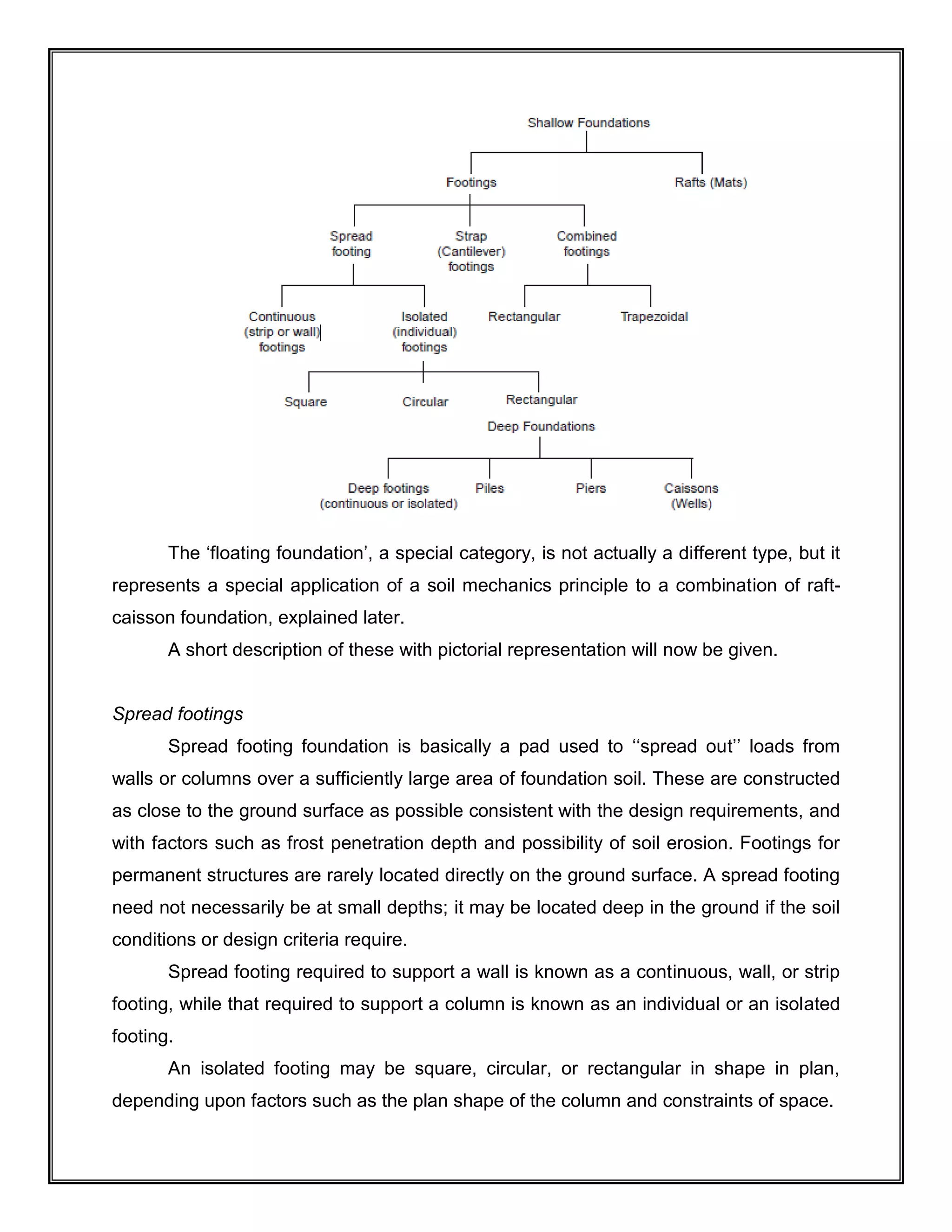
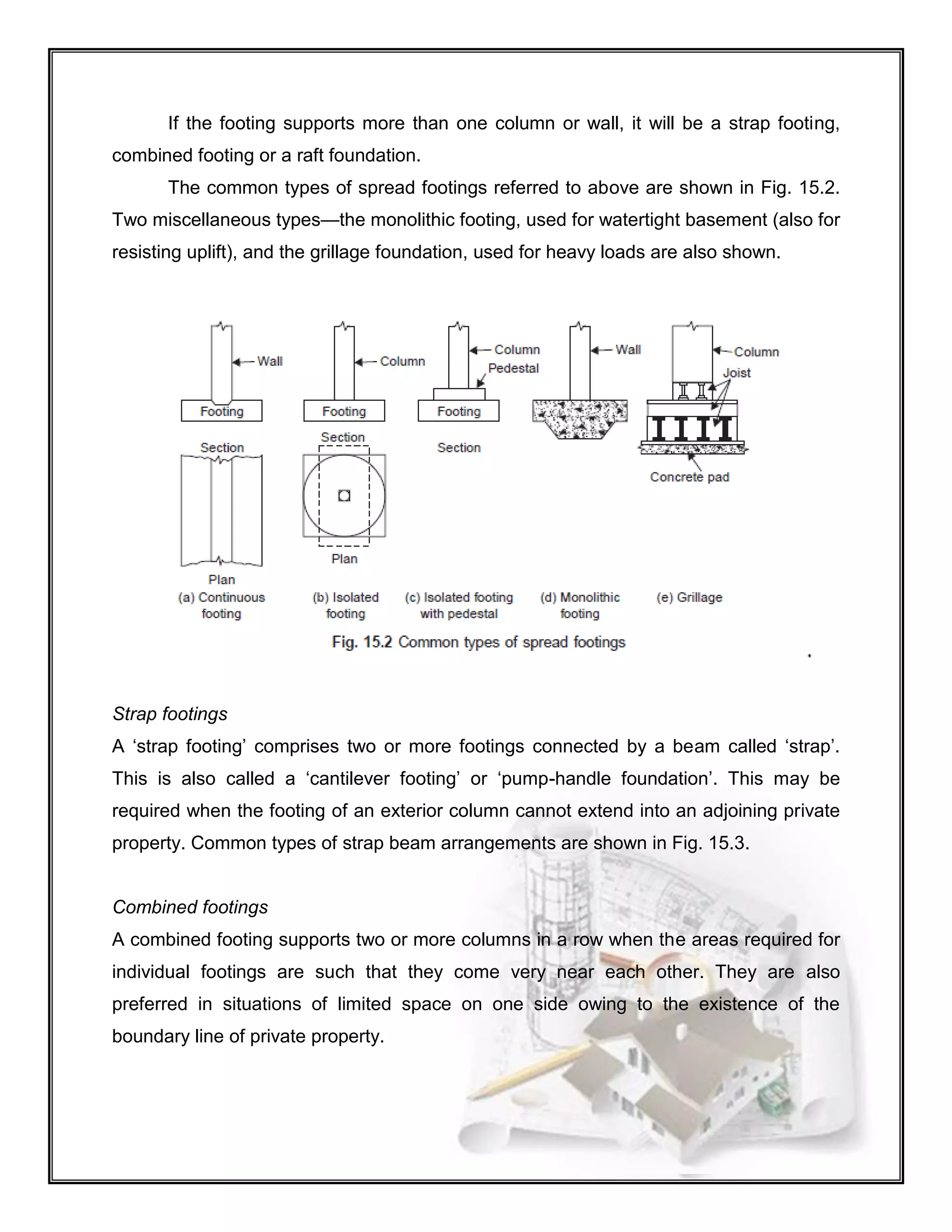
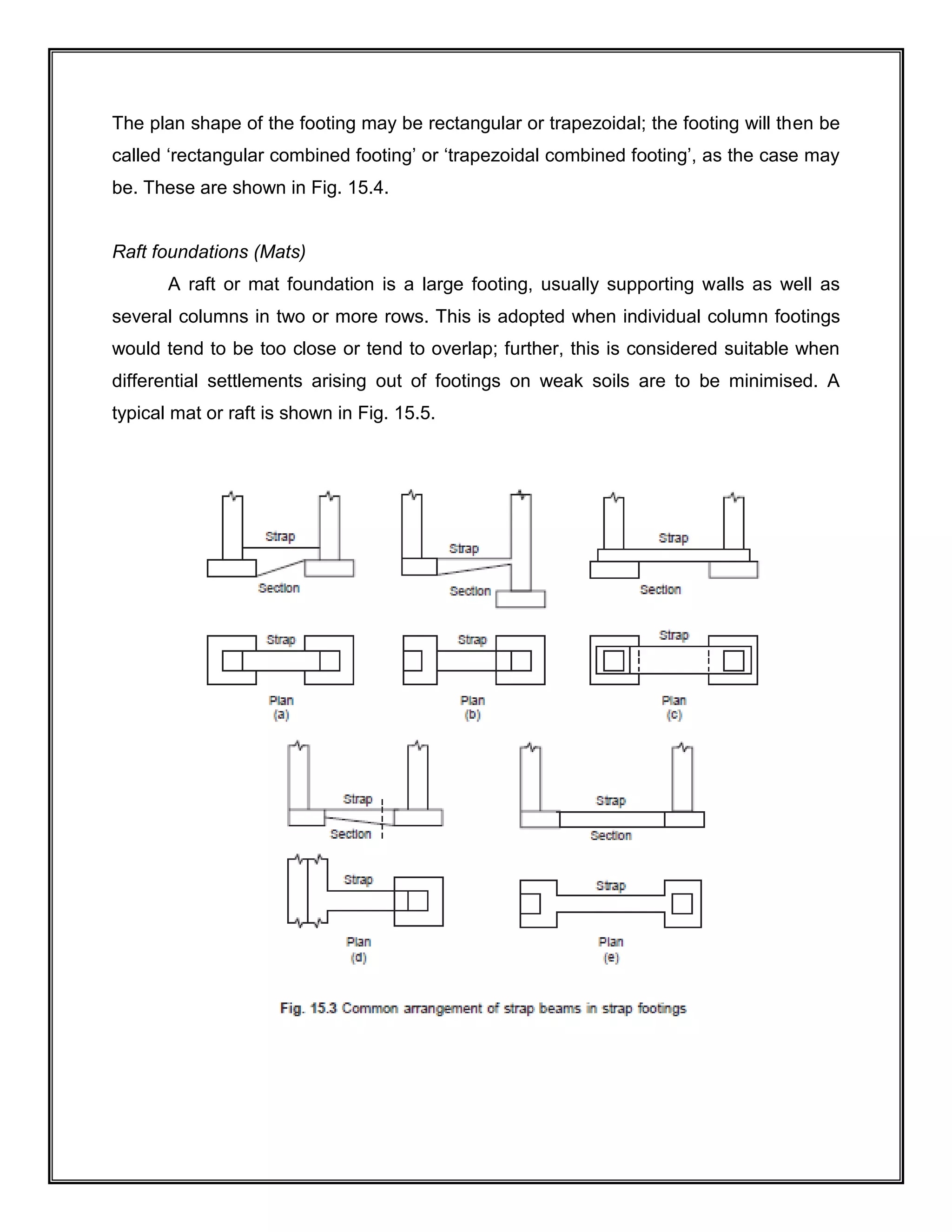
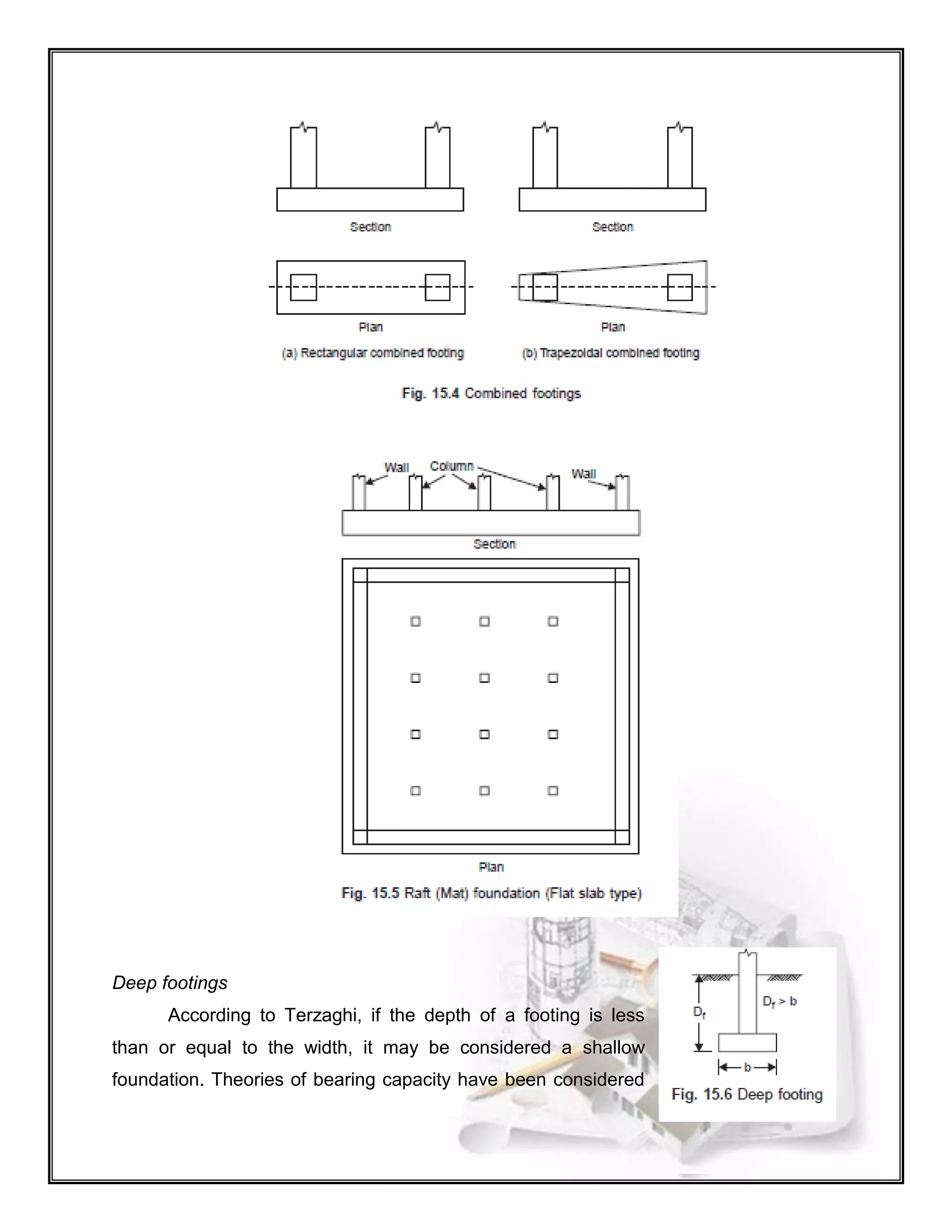
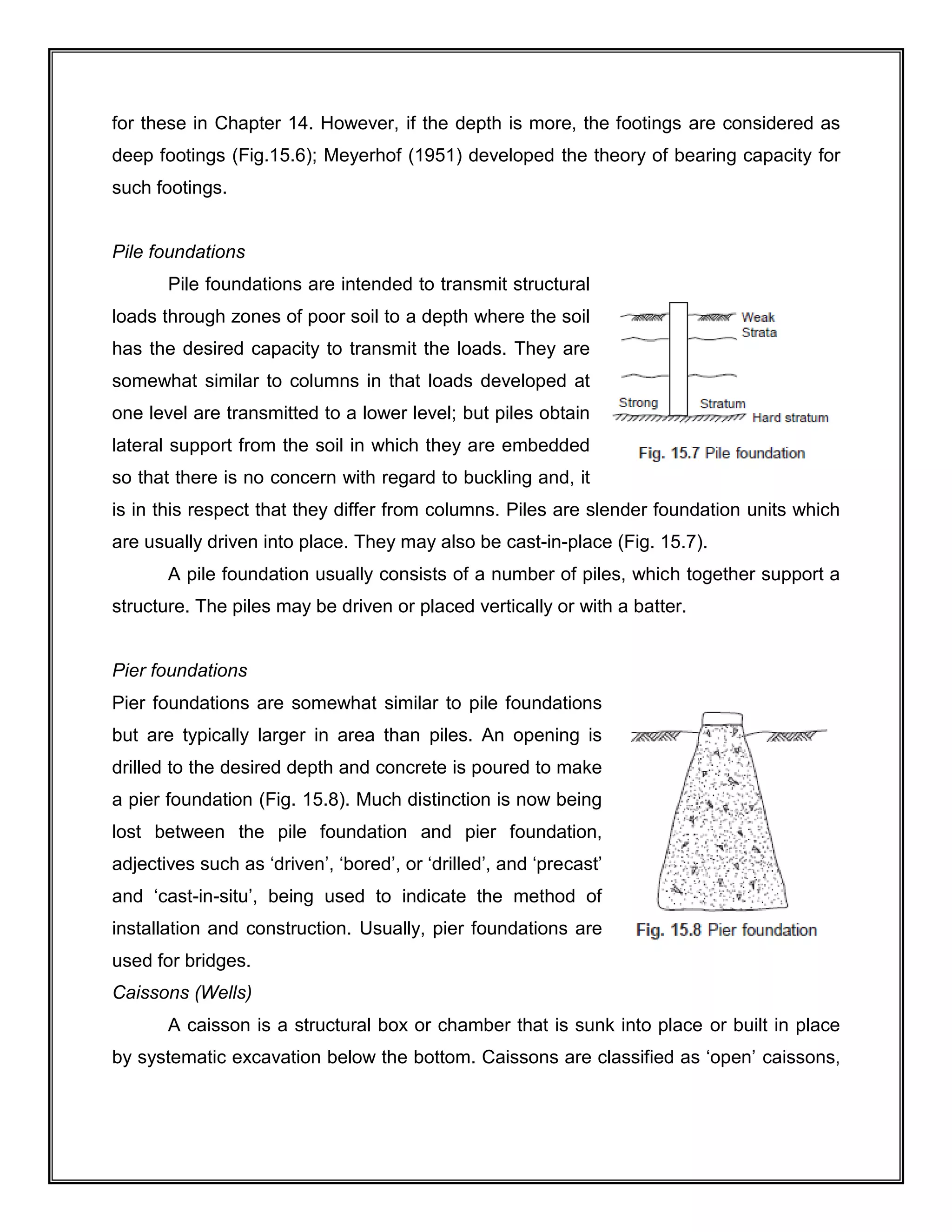
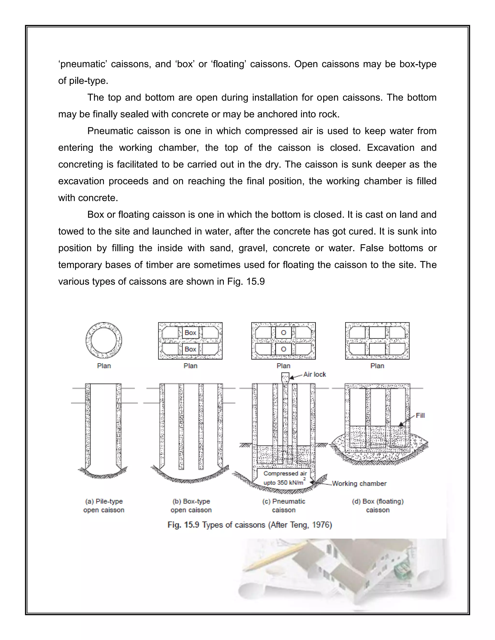
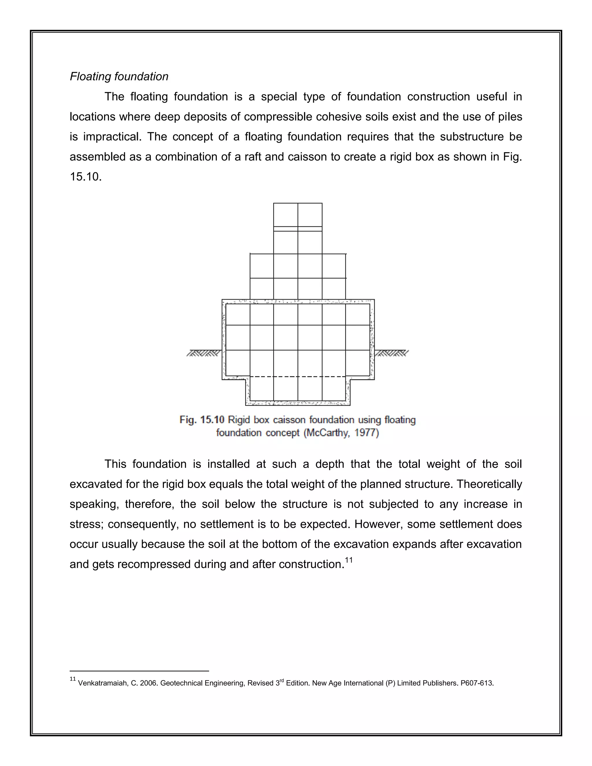
SlideShare a Scribd company logo
Technological University of the Philippines
Ayala Blvd. Ermita, Manila
College of Engineering
Department of Civil Engineering
CE 521-5A
Foundation Engineering, Lec.
Assignment No.1
Introduction to Foundation Engineering
Navarro, Brylle Ephraiem Q.
10-205-053
June 24, 2014
Engr. Jesus Ray M. Mansayon
Instructor
Define/Discuss/Enumerate/Differentiate the following:
1. Soil Mechanics, Geotechnical Engineering, and Foundation Engineering
SOIL MECHANICS
Soil mechanics is a branch of engineering mechanics that describes the
behaviour of soils. It differs from fluid mechanics and solid mechanics in the sense that
soils consist of a heterogeneous mixture of fluids (usually air and water) and particles
(usually clay, silt, sand, and gravel) but soil may also contain organic solids, liquids, and
gasses and other matter.1234
Along with rock mechanics, soil mechanics provides the
theoretical basis for analysis in geotechnical engineering,5
a sub discipline of Civil
engineering, and engineering geology, a sub discipline of geology. Soil mechanics is
used to analyze the deformations of and flow of fluids within natural and man-made
structures that are supported on or made of soil, or structures that are buried in
soils.6
Example applications are building and bridge foundations, retaining walls, dams,
and buried pipeline systems. Principles of soil mechanics are also used in related
disciplines such as engineering geology, geophysical engineering, coastal
engineering, agricultural engineering, hydrology and soil physics.
GEOTECHNICAL ENGINEERING
Geotechnical engineering is the branch of civil engineering concerned with the
engineering behaviour of earth materials. Geotechnical engineering is important in civil
engineering, but is also used by military, mining, petroleum, or any other engineering
concerned with construction on or in the ground. Geotechnical engineering uses
principles of soil mechanics and rock mechanics to investigate subsurface conditions
and materials; determine the relevant physical/mechanical and chemical properties of
these materials; evaluate stability of natural slopes and man-made soil deposits; assess
1
Mitchell, J.K., and Soga, K. (2005) Fundamentals of soil behavior, Third edition, John Wiley and Sons, Inc., ISBN 978-0-471-46302-7.
2
Santamarina, J.C., Klein, K.A., & Fam, M.A. (2001). Soils and Waves: Particulate Materials Behavior, Characterization and Process
Monitoring. Wiley. ISBN 978-0-471-49058-6..
3
Powrie, W., Spon Press, 2004, Soil Mechanics - 2nd ed ISBN 0-415-31156-X
4
A Guide to Soil Mechanics, Bolton, Malcolm,Macmillan Press, 1979. ISBN 0-333-18932-0
5
Fang, Y., Spon Press, 2006, Introductory Geotechnical Engineering
6
Lambe, T. William & Robert V. Whitman. Soil Mechanics. Wiley, 1991; p. 29. ISBN 978-0-471-51192-2
risks posed by site conditions; design earthworks and structure foundations; and
monitor site conditions, earthwork and foundation construction.78
FOUNDATION ENGINEERING
Foundation Engineering is the engineering field of study devoted to the design
of those structures which support other structures, most typically buildings, bridges or
transportation infrastructure. It is at the periphery of Civil, Structural and Geotechnical
Engineering disciplines and has distinct focus on soil-structure interaction.
2. Foundation Engineer
The title Foundation Engineer is given to the person who by reason of training
and experience is sufficiently versed in scientific principles and engineering judgment to
design a foundation.
The necessary scientific principles are acquired through formal educational
courses in geo-technical (soil mechanics, geology, foundation engineering) and
structural (analysis, design in reinforced concrete and steel, etc.) engineering and
continued self-study via short-courses, professional conferences, journal reading, and
the like.
Because of the heterogeneous nature of soil and rock masses, two foundations- even
on adjacent construction sites- will seldom be the same except by coincidence. Since
every foundation represents at least partly a venture into the unknown, it is of great
value to have access to other’s solutions obtained from conference presentations,
journal papers, and textbook condensations of appropriate literature. The amalgamation
of experience, study of what others have done in somewhat similar situations, and the
site-specific geotechnical information to produce an economical, practical, and safe
substructure design is application of engineering judgment.
The following steps are the minimum required for designing a foundation:
7
Terzaghi, K., Peck, R.B. and Mesri, G. (1996), Soil Mechanics in Engineering Practice 3rd Ed., John Wiley & Sons, Inc. ISBN 0-471-08658-
4
8
Holtz, R. and Kovacs, W. (1981), An Introduction to Geotechnical Engineering, Prentice-Hall, Inc. ISBN 0-13-484394-0
1. Locate the site and the position of load. A rough estimate of the foundation
load(s) is usually provided by the client or made in-house. Depending on the site
or load system complexity, a literature survey may be started to see how others
have approached similar problems.
2. Physically inspect the site for any geological or other evidence that may
indicate a potential design problem that will have to be taken into account when
making the design or giving a design recommendation. Supplement this
inspection with any previously obtained soil data.
3. Establish the field exploration program and, on the basis of discovery (or what
is found in the initial phase), set up the necessary supplemental field testing and
any laboratory test program.
4. Determine the necessary soil design parameters based on integration of test
data, scientific principles, and engineering judgment. Simple or complex
computer analyses may be involved. For complex problems, compare the
recommended data with published literature or engage another geotechnical
consultant to give an outside perspective to the results.
5. Design the foundation using the soil parameters from step 4. The foundation
should be economical and be able to be built by the available construction
personnel. Take into account practical construction tolerances and local
construction practices. Interact closely with all concerned (client, engineers,
architect, contractor) so that the substructure system is not excessively
overdesigned and risk is kept within acceptable levels. A computer may be used
extensively (or not at all) in this step.
The foundation engineer should be experienced in and have participation in all
five of the preceding steps. In practice this often is not the case. An independent
geotechnical firm specializing in sol exploration, soil testing, design of landfills,
embankments, water pollution control, etc. often assigns one of its geotechnical
designers to do steps 1 through 4.
The output of step 4 is given to the client- often a foundation engineer who
specializes in the design of the structural elements making up the substructure system.
The principal deficiency in this approach is the tendency to treat the design soil
parameters- obtained from soil tests of variable quality, heavily supplemented with
engineering judgment- as precise numbers whose magnitude is totally inviolable. Thus,
the foundation engineer and geotechnical consultant must work closely together, or at
least have frequent conferences as the design progresses. It should be evident that
both parties need to appreciate the problems of each other and, particularly, that the
foundation design engineer must be aware of the approximate methods used to obtain
the soil parameters being used. This understanding can be obtained by each having
training in the other’s specialty.
To this end, the primary focus of this text will be on analysis and design of the
interfacing elements for buildings, machines, and retaining structures and on those soil
mechanics principles used to obtain the necessary soil parameters required to
accomplish the design. Specific foundation elements to be considered include shallow
elements such as footings and mats and deep elements such as piles and drilled piers.
Geotechnical considerations will primarily be on strength and deformation and those
soil-water phenomena that affect strength and deformation with the current trend to
using sites with marginal soil parameters for major projects, methods to improve the
strength and deformation characteristics through soil improvement methods.9
3. Four Performance Requirements
STRENGTH REQUIREMENTS
Strength requirements are intended to avoid catastrophic failures. There are
two types: geotechnical strength requirements and structural strength requirements.
Geotechnical strength requirements are those that address the ability of the
soil or rock to accept the loads imparted by the foundation without failing. The strength
of soil is governed by its capacity to sustain shear stresses, so we satisfy geotechnical
9
Bowles, Joseph. 1995. Foundation Analysis and Design., 5th Edition., USA. P24-26
strength requirements by comparing shear stresses with shear strengths and designing
accordingly.
In the case of spread footing foundations, geotechnical strength is expressed as
the bearing capacity of the soil. If the load-bearing capacity of the soil is exceeded, the
resulting shear failure is called a bearing capacity failure as shown in the Figure 1.
Structural strength requirements address the foundation’s structural integrity
and its ability to safely carry the applied loads. Foundations that are loaded beyond
structural capacity will, in principle, fail catastrophically.
Structural strength analyses are conducted using the ASD or LRFD methods,
depending on the types of foundation, the structural materials, and the governing code.
SERVICEABILITY REQUIREMENTS
Serviceability requirements are intended to produce foundations that perform
well when subjected to the service loads. These requirements include:
 Settlement – Most foundations experience some downward movement as
a result of the applied loads. This movement is called settlement. Keeping
settlements within tolerable limits is usually the most important foundation
serviceability requirement.
Fig.1. A bearing capacity
failure beneath a spread
footing foundation. The soil
has failed in shear, causing
the foundation to collapse
 Heave – Sometimes foundations move upward instead of downward. We
call this upward movement heave. The most common source of heave is
the swelling of expansive soils.
 Tilt – When settlement or heave occurs only on one side of the structure,
it may begin to tilt. The Leaning Tower of Pisa is an extreme example of
tilt.
 Lateral movement – Foundations subjected to lateral loads (shear or
moment) deform horizontally. This lateral movement also must remain
within acceptable limits to avoid structural distress.
 Vibration – Some foundations, such as those supporting certain kinds of
heavy machinery, are subjected to strong vibrations. Such foundations
need to accommodate these vibrations without experiencing resonance or
other problems.
 Durability – Foundations must be resistant to the various physical,
chemical, and biological processes that cause deterioration. This is
especially important in waterfront structures, such as docks and piers.
Failure to satisfy these requirements generally results in increased maintenance
costs, aesthetic problems, diminished usefulness of the structure, and other similar
effects.
Fig.2. Modes of settlement: (a)
uniform, (b) tilting with no
distortion, (c) distortion
CONSTRUCTIBILITY REQUIREMENTS
Constructibility requirements meaning the foundation must be designed such
that the contractor can build it without having to use extraordinary method or equipment.
ECONOMIC REQUIREMENTS
Economic requirements are intended to produce designs that minimize the
required quantity of construction materials do not necessarily minimize the cost. In
some cases, designs that use more materials may be easier to build, and thus have a
lower overall cost.10
4. Classification of Foundation
The various types of structural foundations may be grouped into two broad
categories — shallow foundations and deep foundations. The classification indicates the
depth of the foundation relative to its size and the depth of the soil providing most of the
support. According to Terzaghi, a foundation is shallow if its depth is equal to or less
than its width and deep when it exceeds the width.
Further classification of shallow foundations and deep foundations is as follows:
10
http://infohost.nmt.edu/~Mehrdad/foundation/hdout/PerformanceRequirements.pdf
The ‘floating foundation’, a special category, is not actually a different type, but it
represents a special application of a soil mechanics principle to a combination of raft-
caisson foundation, explained later.
A short description of these with pictorial representation will now be given.
Spread footings
Spread footing foundation is basically a pad used to ‘‘spread out’’ loads from
walls or columns over a sufficiently large area of foundation soil. These are constructed
as close to the ground surface as possible consistent with the design requirements, and
with factors such as frost penetration depth and possibility of soil erosion. Footings for
permanent structures are rarely located directly on the ground surface. A spread footing
need not necessarily be at small depths; it may be located deep in the ground if the soil
conditions or design criteria require.
Spread footing required to support a wall is known as a continuous, wall, or strip
footing, while that required to support a column is known as an individual or an isolated
footing.
An isolated footing may be square, circular, or rectangular in shape in plan,
depending upon factors such as the plan shape of the column and constraints of space.
If the footing supports more than one column or wall, it will be a strap footing,
combined footing or a raft foundation.
The common types of spread footings referred to above are shown in Fig. 15.2.
Two miscellaneous types—the monolithic footing, used for watertight basement (also for
resisting uplift), and the grillage foundation, used for heavy loads are also shown.
Strap footings
A ‘strap footing’ comprises two or more footings connected by a beam called ‘strap’.
This is also called a ‘cantilever footing’ or ‘pump-handle foundation’. This may be
required when the footing of an exterior column cannot extend into an adjoining private
property. Common types of strap beam arrangements are shown in Fig. 15.3.
Combined footings
A combined footing supports two or more columns in a row when the areas required for
individual footings are such that they come very near each other. They are also
preferred in situations of limited space on one side owing to the existence of the
boundary line of private property.
The plan shape of the footing may be rectangular or trapezoidal; the footing will then be
called ‘rectangular combined footing’ or ‘trapezoidal combined footing’, as the case may
be. These are shown in Fig. 15.4.
Raft foundations (Mats)
A raft or mat foundation is a large footing, usually supporting walls as well as
several columns in two or more rows. This is adopted when individual column footings
would tend to be too close or tend to overlap; further, this is considered suitable when
differential settlements arising out of footings on weak soils are to be minimised. A
typical mat or raft is shown in Fig. 15.5.
Deep footings
According to Terzaghi, if the depth of a footing is less
than or equal to the width, it may be considered a shallow
foundation. Theories of bearing capacity have been considered
for these in Chapter 14. However, if the depth is more, the footings are considered as
deep footings (Fig.15.6); Meyerhof (1951) developed the theory of bearing capacity for
such footings.
Pile foundations
Pile foundations are intended to transmit structural
loads through zones of poor soil to a depth where the soil
has the desired capacity to transmit the loads. They are
somewhat similar to columns in that loads developed at
one level are transmitted to a lower level; but piles obtain
lateral support from the soil in which they are embedded
so that there is no concern with regard to buckling and, it
is in this respect that they differ from columns. Piles are slender foundation units which
are usually driven into place. They may also be cast-in-place (Fig. 15.7).
A pile foundation usually consists of a number of piles, which together support a
structure. The piles may be driven or placed vertically or with a batter.
Pier foundations
Pier foundations are somewhat similar to pile foundations
but are typically larger in area than piles. An opening is
drilled to the desired depth and concrete is poured to make
a pier foundation (Fig. 15.8). Much distinction is now being
lost between the pile foundation and pier foundation,
adjectives such as ‘driven’, ‘bored’, or ‘drilled’, and ‘precast’
and ‘cast-in-situ’, being used to indicate the method of
installation and construction. Usually, pier foundations are
used for bridges.
Caissons (Wells)
A caisson is a structural box or chamber that is sunk into place or built in place
by systematic excavation below the bottom. Caissons are classified as ‘open’ caissons,
‘pneumatic’ caissons, and ‘box’ or ‘floating’ caissons. Open caissons may be box-type
of pile-type.
The top and bottom are open during installation for open caissons. The bottom
may be finally sealed with concrete or may be anchored into rock.
Pneumatic caisson is one in which compressed air is used to keep water from
entering the working chamber, the top of the caisson is closed. Excavation and
concreting is facilitated to be carried out in the dry. The caisson is sunk deeper as the
excavation proceeds and on reaching the final position, the working chamber is filled
with concrete.
Box or floating caisson is one in which the bottom is closed. It is cast on land and
towed to the site and launched in water, after the concrete has got cured. It is sunk into
position by filling the inside with sand, gravel, concrete or water. False bottoms or
temporary bases of timber are sometimes used for floating the caisson to the site. The
various types of caissons are shown in Fig. 15.9
Floating foundation
The floating foundation is a special type of foundation construction useful in
locations where deep deposits of compressible cohesive soils exist and the use of piles
is impractical. The concept of a floating foundation requires that the substructure be
assembled as a combination of a raft and caisson to create a rigid box as shown in Fig.
15.10.
This foundation is installed at such a depth that the total weight of the soil
excavated for the rigid box equals the total weight of the planned structure. Theoretically
speaking, therefore, the soil below the structure is not subjected to any increase in
stress; consequently, no settlement is to be expected. However, some settlement does
occur usually because the soil at the bottom of the excavation expands after excavation
and gets recompressed during and after construction.11
11
Venkatramaiah, C. 2006. Geotechnical Engineering, Revised 3rd
Edition. New Age International (P) Limited Publishers. P607-613.

More Related Content

What's hot

Scope of studying engineering geology
Scope of studying engineering geologyScope of studying engineering geology
Scope of studying engineering geology
Prof. A.Balasubramanian
 
Scope of Geology for Civil Engineer
Scope of Geology for Civil EngineerScope of Geology for Civil Engineer
Scope of Geology for Civil Engineer
!SYOU co-designed sneakers
 
Engineering geology
Engineering geologyEngineering geology
Engineering geology
Rounak Kapoor
 
Introduction to soil engineering
Introduction to soil engineeringIntroduction to soil engineering
Introduction to soil engineering
Nikunj Hindocha
 
150 branches of geology
150 branches of geology150 branches of geology
150 branches of geology
Prof. A.Balasubramanian
 
Introduction to geology
Introduction to geologyIntroduction to geology
Introduction to geology
RAMPRASAD KUMAWAT
 
1.1 introduction of geology,Branches and Scope of Geology
1.1 introduction of geology,Branches and Scope of Geology1.1 introduction of geology,Branches and Scope of Geology
1.1 introduction of geology,Branches and Scope of Geology
Ram Kumawat
 
geotech laboratory works
geotech laboratory worksgeotech laboratory works
geotech laboratory works
Marvin Ken
 
1 Unit-I Scope of Geology in Engineering
1 Unit-I Scope of Geology in Engineering1 Unit-I Scope of Geology in Engineering
1 Unit-I Scope of Geology in Engineering
sam abbas
 
Geology
Geology Geology
Geology
Tarun kumar
 
Geotechnical Engineering
Geotechnical EngineeringGeotechnical Engineering
Geotechnical Engineering
Sri Civil
 
2.engineering geology
2.engineering geology2.engineering geology
2.engineering geology
Sarfaraz Ahmed
 
Geology Introduction
Geology IntroductionGeology Introduction
Geology Introduction
Pramod Hanamgond
 
Module 1 introduction to geology
Module 1   introduction to geologyModule 1   introduction to geology
Module 1 introduction to geology
Mukifin Miftah
 
What is geology and scope of geology
What is geology and scope of geologyWhat is geology and scope of geology
What is geology and scope of geology
Kaustubh Sane
 
Geology
GeologyGeology
Geology
Tarun kumar
 
chapter 1 Geotechnical engineering
chapter 1 Geotechnical engineeringchapter 1 Geotechnical engineering
chapter 1 Geotechnical engineering
Livingstone Gazana
 
CONSTRUCTIVE METHODS OF PROTECTING BUILDINGS FROM SEISMIC EXPOSURE
CONSTRUCTIVE METHODS OF PROTECTING BUILDINGS FROM SEISMIC EXPOSURECONSTRUCTIVE METHODS OF PROTECTING BUILDINGS FROM SEISMIC EXPOSURE
CONSTRUCTIVE METHODS OF PROTECTING BUILDINGS FROM SEISMIC EXPOSURE
IAEME Publication
 
Relation of Geology
Relation of GeologyRelation of Geology
Relation of Geology
Kalpa Mazumdar
 
Geology ppt.
Geology ppt.Geology ppt.
Geology ppt.
Dinesh ppt Devloper
 

What's hot (20)

Scope of studying engineering geology
Scope of studying engineering geologyScope of studying engineering geology
Scope of studying engineering geology
 
Scope of Geology for Civil Engineer
Scope of Geology for Civil EngineerScope of Geology for Civil Engineer
Scope of Geology for Civil Engineer
 
Engineering geology
Engineering geologyEngineering geology
Engineering geology
 
Introduction to soil engineering
Introduction to soil engineeringIntroduction to soil engineering
Introduction to soil engineering
 
150 branches of geology
150 branches of geology150 branches of geology
150 branches of geology
 
Introduction to geology
Introduction to geologyIntroduction to geology
Introduction to geology
 
1.1 introduction of geology,Branches and Scope of Geology
1.1 introduction of geology,Branches and Scope of Geology1.1 introduction of geology,Branches and Scope of Geology
1.1 introduction of geology,Branches and Scope of Geology
 
geotech laboratory works
geotech laboratory worksgeotech laboratory works
geotech laboratory works
 
1 Unit-I Scope of Geology in Engineering
1 Unit-I Scope of Geology in Engineering1 Unit-I Scope of Geology in Engineering
1 Unit-I Scope of Geology in Engineering
 
Geology
Geology Geology
Geology
 
Geotechnical Engineering
Geotechnical EngineeringGeotechnical Engineering
Geotechnical Engineering
 
2.engineering geology
2.engineering geology2.engineering geology
2.engineering geology
 
Geology Introduction
Geology IntroductionGeology Introduction
Geology Introduction
 
Module 1 introduction to geology
Module 1   introduction to geologyModule 1   introduction to geology
Module 1 introduction to geology
 
What is geology and scope of geology
What is geology and scope of geologyWhat is geology and scope of geology
What is geology and scope of geology
 
Geology
GeologyGeology
Geology
 
chapter 1 Geotechnical engineering
chapter 1 Geotechnical engineeringchapter 1 Geotechnical engineering
chapter 1 Geotechnical engineering
 
CONSTRUCTIVE METHODS OF PROTECTING BUILDINGS FROM SEISMIC EXPOSURE
CONSTRUCTIVE METHODS OF PROTECTING BUILDINGS FROM SEISMIC EXPOSURECONSTRUCTIVE METHODS OF PROTECTING BUILDINGS FROM SEISMIC EXPOSURE
CONSTRUCTIVE METHODS OF PROTECTING BUILDINGS FROM SEISMIC EXPOSURE
 
Relation of Geology
Relation of GeologyRelation of Geology
Relation of Geology
 
Geology ppt.
Geology ppt.Geology ppt.
Geology ppt.
 

Similar to Navarro a#1 introduction to foundation engineering_2014-2015

INTRODUCTION_AND_geotechnical_activities(2).pptx
INTRODUCTION_AND_geotechnical_activities(2).pptxINTRODUCTION_AND_geotechnical_activities(2).pptx
INTRODUCTION_AND_geotechnical_activities(2).pptx
CarolTumaneng
 
Course outline 1
Course outline 1Course outline 1
Course outline 1
Zakee Kazmee
 
F0373040048
F0373040048F0373040048
F0373040048
theijes
 
BOS_Foundationl Engineering PPT.pptx
BOS_Foundationl Engineering PPT.pptxBOS_Foundationl Engineering PPT.pptx
BOS_Foundationl Engineering PPT.pptx
MrBhaskarWabhitkar
 
Rs1042 civil engineering 11 & 12 2074
Rs1042  civil engineering 11 & 12 2074Rs1042  civil engineering 11 & 12 2074
Rs1042 civil engineering 11 & 12 2074
Mahendra Poudel
 
Sachpazis Costas: Geotechnical Engineering: A student's Perspective Introduction
Sachpazis Costas: Geotechnical Engineering: A student's Perspective IntroductionSachpazis Costas: Geotechnical Engineering: A student's Perspective Introduction
Sachpazis Costas: Geotechnical Engineering: A student's Perspective Introduction
Dr.Costas Sachpazis
 
Ce461csdcdcdscdsc
Ce461csdcdcdscdscCe461csdcdcdscdsc
Ce461csdcdcdscdsc
Ali M. Shehadeh
 
Engineering Geology Lecture 1
Engineering Geology Lecture 1Engineering Geology Lecture 1
Engineering Geology Lecture 1
University of Gondar
 
I05537486
I05537486I05537486
I05537486
IOSR-JEN
 
Introduction to Site Investigation Methods
Introduction to Site Investigation MethodsIntroduction to Site Investigation Methods
Introduction to Site Investigation Methods
MohdBilal430488
 
SOIL EXPLORATION AND GEOTECHNICAL DESIGN OF A FOUNDATION
SOIL EXPLORATION AND GEOTECHNICAL DESIGN OF A FOUNDATIONSOIL EXPLORATION AND GEOTECHNICAL DESIGN OF A FOUNDATION
SOIL EXPLORATION AND GEOTECHNICAL DESIGN OF A FOUNDATION
IRJET Journal
 
Importance of geotechnical engineering knowledge to civil engineers.pdf
Importance of geotechnical engineering knowledge to civil engineers.pdfImportance of geotechnical engineering knowledge to civil engineers.pdf
Importance of geotechnical engineering knowledge to civil engineers.pdf
ankit482504
 
Geo technical engineering v.n.s.murthy
Geo technical engineering v.n.s.murthyGeo technical engineering v.n.s.murthy
Geo technical engineering v.n.s.murthy
Yeswanth Raghavendra
 
Ce6405 sm
Ce6405 smCe6405 sm
Unit1 hbn
Unit1 hbnUnit1 hbn
Unit1 hbn
Pavan Kumar N
 
Application of structural geology to the solution of engineering problems
Application of structural geology to  the solution of engineering problemsApplication of structural geology to  the solution of engineering problems
Application of structural geology to the solution of engineering problems
Rkosgaming
 
Comparative Study of SMRF Structure in the Different Conditions of Soil: A Re...
Comparative Study of SMRF Structure in the Different Conditions of Soil: A Re...Comparative Study of SMRF Structure in the Different Conditions of Soil: A Re...
Comparative Study of SMRF Structure in the Different Conditions of Soil: A Re...
IRJET Journal
 
Sm Chapter I
Sm Chapter ISm Chapter I
Sm Chapter I
jagadeesha M U
 
A05710107
A05710107A05710107
A05710107
IOSR-JEN
 
Intro to engg geology
Intro to engg geologyIntro to engg geology
Intro to engg geology
1971995
 

Similar to Navarro a#1 introduction to foundation engineering_2014-2015 (20)

INTRODUCTION_AND_geotechnical_activities(2).pptx
INTRODUCTION_AND_geotechnical_activities(2).pptxINTRODUCTION_AND_geotechnical_activities(2).pptx
INTRODUCTION_AND_geotechnical_activities(2).pptx
 
Course outline 1
Course outline 1Course outline 1
Course outline 1
 
F0373040048
F0373040048F0373040048
F0373040048
 
BOS_Foundationl Engineering PPT.pptx
BOS_Foundationl Engineering PPT.pptxBOS_Foundationl Engineering PPT.pptx
BOS_Foundationl Engineering PPT.pptx
 
Rs1042 civil engineering 11 & 12 2074
Rs1042  civil engineering 11 & 12 2074Rs1042  civil engineering 11 & 12 2074
Rs1042 civil engineering 11 & 12 2074
 
Sachpazis Costas: Geotechnical Engineering: A student's Perspective Introduction
Sachpazis Costas: Geotechnical Engineering: A student's Perspective IntroductionSachpazis Costas: Geotechnical Engineering: A student's Perspective Introduction
Sachpazis Costas: Geotechnical Engineering: A student's Perspective Introduction
 
Ce461csdcdcdscdsc
Ce461csdcdcdscdscCe461csdcdcdscdsc
Ce461csdcdcdscdsc
 
Engineering Geology Lecture 1
Engineering Geology Lecture 1Engineering Geology Lecture 1
Engineering Geology Lecture 1
 
I05537486
I05537486I05537486
I05537486
 
Introduction to Site Investigation Methods
Introduction to Site Investigation MethodsIntroduction to Site Investigation Methods
Introduction to Site Investigation Methods
 
SOIL EXPLORATION AND GEOTECHNICAL DESIGN OF A FOUNDATION
SOIL EXPLORATION AND GEOTECHNICAL DESIGN OF A FOUNDATIONSOIL EXPLORATION AND GEOTECHNICAL DESIGN OF A FOUNDATION
SOIL EXPLORATION AND GEOTECHNICAL DESIGN OF A FOUNDATION
 
Importance of geotechnical engineering knowledge to civil engineers.pdf
Importance of geotechnical engineering knowledge to civil engineers.pdfImportance of geotechnical engineering knowledge to civil engineers.pdf
Importance of geotechnical engineering knowledge to civil engineers.pdf
 
Geo technical engineering v.n.s.murthy
Geo technical engineering v.n.s.murthyGeo technical engineering v.n.s.murthy
Geo technical engineering v.n.s.murthy
 
Ce6405 sm
Ce6405 smCe6405 sm
Ce6405 sm
 
Unit1 hbn
Unit1 hbnUnit1 hbn
Unit1 hbn
 
Application of structural geology to the solution of engineering problems
Application of structural geology to  the solution of engineering problemsApplication of structural geology to  the solution of engineering problems
Application of structural geology to the solution of engineering problems
 
Comparative Study of SMRF Structure in the Different Conditions of Soil: A Re...
Comparative Study of SMRF Structure in the Different Conditions of Soil: A Re...Comparative Study of SMRF Structure in the Different Conditions of Soil: A Re...
Comparative Study of SMRF Structure in the Different Conditions of Soil: A Re...
 
Sm Chapter I
Sm Chapter ISm Chapter I
Sm Chapter I
 
A05710107
A05710107A05710107
A05710107
 
Intro to engg geology
Intro to engg geologyIntro to engg geology
Intro to engg geology
 

Navarro a#1 introduction to foundation engineering_2014-2015

  • 1. Technological University of the Philippines Ayala Blvd. Ermita, Manila College of Engineering Department of Civil Engineering CE 521-5A Foundation Engineering, Lec. Assignment No.1 Introduction to Foundation Engineering Navarro, Brylle Ephraiem Q. 10-205-053 June 24, 2014 Engr. Jesus Ray M. Mansayon Instructor
  • 2. Define/Discuss/Enumerate/Differentiate the following: 1. Soil Mechanics, Geotechnical Engineering, and Foundation Engineering SOIL MECHANICS Soil mechanics is a branch of engineering mechanics that describes the behaviour of soils. It differs from fluid mechanics and solid mechanics in the sense that soils consist of a heterogeneous mixture of fluids (usually air and water) and particles (usually clay, silt, sand, and gravel) but soil may also contain organic solids, liquids, and gasses and other matter.1234 Along with rock mechanics, soil mechanics provides the theoretical basis for analysis in geotechnical engineering,5 a sub discipline of Civil engineering, and engineering geology, a sub discipline of geology. Soil mechanics is used to analyze the deformations of and flow of fluids within natural and man-made structures that are supported on or made of soil, or structures that are buried in soils.6 Example applications are building and bridge foundations, retaining walls, dams, and buried pipeline systems. Principles of soil mechanics are also used in related disciplines such as engineering geology, geophysical engineering, coastal engineering, agricultural engineering, hydrology and soil physics. GEOTECHNICAL ENGINEERING Geotechnical engineering is the branch of civil engineering concerned with the engineering behaviour of earth materials. Geotechnical engineering is important in civil engineering, but is also used by military, mining, petroleum, or any other engineering concerned with construction on or in the ground. Geotechnical engineering uses principles of soil mechanics and rock mechanics to investigate subsurface conditions and materials; determine the relevant physical/mechanical and chemical properties of these materials; evaluate stability of natural slopes and man-made soil deposits; assess 1 Mitchell, J.K., and Soga, K. (2005) Fundamentals of soil behavior, Third edition, John Wiley and Sons, Inc., ISBN 978-0-471-46302-7. 2 Santamarina, J.C., Klein, K.A., & Fam, M.A. (2001). Soils and Waves: Particulate Materials Behavior, Characterization and Process Monitoring. Wiley. ISBN 978-0-471-49058-6.. 3 Powrie, W., Spon Press, 2004, Soil Mechanics - 2nd ed ISBN 0-415-31156-X 4 A Guide to Soil Mechanics, Bolton, Malcolm,Macmillan Press, 1979. ISBN 0-333-18932-0 5 Fang, Y., Spon Press, 2006, Introductory Geotechnical Engineering 6 Lambe, T. William & Robert V. Whitman. Soil Mechanics. Wiley, 1991; p. 29. ISBN 978-0-471-51192-2
  • 3. risks posed by site conditions; design earthworks and structure foundations; and monitor site conditions, earthwork and foundation construction.78 FOUNDATION ENGINEERING Foundation Engineering is the engineering field of study devoted to the design of those structures which support other structures, most typically buildings, bridges or transportation infrastructure. It is at the periphery of Civil, Structural and Geotechnical Engineering disciplines and has distinct focus on soil-structure interaction. 2. Foundation Engineer The title Foundation Engineer is given to the person who by reason of training and experience is sufficiently versed in scientific principles and engineering judgment to design a foundation. The necessary scientific principles are acquired through formal educational courses in geo-technical (soil mechanics, geology, foundation engineering) and structural (analysis, design in reinforced concrete and steel, etc.) engineering and continued self-study via short-courses, professional conferences, journal reading, and the like. Because of the heterogeneous nature of soil and rock masses, two foundations- even on adjacent construction sites- will seldom be the same except by coincidence. Since every foundation represents at least partly a venture into the unknown, it is of great value to have access to other’s solutions obtained from conference presentations, journal papers, and textbook condensations of appropriate literature. The amalgamation of experience, study of what others have done in somewhat similar situations, and the site-specific geotechnical information to produce an economical, practical, and safe substructure design is application of engineering judgment. The following steps are the minimum required for designing a foundation: 7 Terzaghi, K., Peck, R.B. and Mesri, G. (1996), Soil Mechanics in Engineering Practice 3rd Ed., John Wiley & Sons, Inc. ISBN 0-471-08658- 4 8 Holtz, R. and Kovacs, W. (1981), An Introduction to Geotechnical Engineering, Prentice-Hall, Inc. ISBN 0-13-484394-0
  • 4. 1. Locate the site and the position of load. A rough estimate of the foundation load(s) is usually provided by the client or made in-house. Depending on the site or load system complexity, a literature survey may be started to see how others have approached similar problems. 2. Physically inspect the site for any geological or other evidence that may indicate a potential design problem that will have to be taken into account when making the design or giving a design recommendation. Supplement this inspection with any previously obtained soil data. 3. Establish the field exploration program and, on the basis of discovery (or what is found in the initial phase), set up the necessary supplemental field testing and any laboratory test program. 4. Determine the necessary soil design parameters based on integration of test data, scientific principles, and engineering judgment. Simple or complex computer analyses may be involved. For complex problems, compare the recommended data with published literature or engage another geotechnical consultant to give an outside perspective to the results. 5. Design the foundation using the soil parameters from step 4. The foundation should be economical and be able to be built by the available construction personnel. Take into account practical construction tolerances and local construction practices. Interact closely with all concerned (client, engineers, architect, contractor) so that the substructure system is not excessively overdesigned and risk is kept within acceptable levels. A computer may be used extensively (or not at all) in this step. The foundation engineer should be experienced in and have participation in all five of the preceding steps. In practice this often is not the case. An independent geotechnical firm specializing in sol exploration, soil testing, design of landfills, embankments, water pollution control, etc. often assigns one of its geotechnical designers to do steps 1 through 4.
  • 5. The output of step 4 is given to the client- often a foundation engineer who specializes in the design of the structural elements making up the substructure system. The principal deficiency in this approach is the tendency to treat the design soil parameters- obtained from soil tests of variable quality, heavily supplemented with engineering judgment- as precise numbers whose magnitude is totally inviolable. Thus, the foundation engineer and geotechnical consultant must work closely together, or at least have frequent conferences as the design progresses. It should be evident that both parties need to appreciate the problems of each other and, particularly, that the foundation design engineer must be aware of the approximate methods used to obtain the soil parameters being used. This understanding can be obtained by each having training in the other’s specialty. To this end, the primary focus of this text will be on analysis and design of the interfacing elements for buildings, machines, and retaining structures and on those soil mechanics principles used to obtain the necessary soil parameters required to accomplish the design. Specific foundation elements to be considered include shallow elements such as footings and mats and deep elements such as piles and drilled piers. Geotechnical considerations will primarily be on strength and deformation and those soil-water phenomena that affect strength and deformation with the current trend to using sites with marginal soil parameters for major projects, methods to improve the strength and deformation characteristics through soil improvement methods.9 3. Four Performance Requirements STRENGTH REQUIREMENTS Strength requirements are intended to avoid catastrophic failures. There are two types: geotechnical strength requirements and structural strength requirements. Geotechnical strength requirements are those that address the ability of the soil or rock to accept the loads imparted by the foundation without failing. The strength of soil is governed by its capacity to sustain shear stresses, so we satisfy geotechnical 9 Bowles, Joseph. 1995. Foundation Analysis and Design., 5th Edition., USA. P24-26
  • 6. strength requirements by comparing shear stresses with shear strengths and designing accordingly. In the case of spread footing foundations, geotechnical strength is expressed as the bearing capacity of the soil. If the load-bearing capacity of the soil is exceeded, the resulting shear failure is called a bearing capacity failure as shown in the Figure 1. Structural strength requirements address the foundation’s structural integrity and its ability to safely carry the applied loads. Foundations that are loaded beyond structural capacity will, in principle, fail catastrophically. Structural strength analyses are conducted using the ASD or LRFD methods, depending on the types of foundation, the structural materials, and the governing code. SERVICEABILITY REQUIREMENTS Serviceability requirements are intended to produce foundations that perform well when subjected to the service loads. These requirements include:  Settlement – Most foundations experience some downward movement as a result of the applied loads. This movement is called settlement. Keeping settlements within tolerable limits is usually the most important foundation serviceability requirement. Fig.1. A bearing capacity failure beneath a spread footing foundation. The soil has failed in shear, causing the foundation to collapse
  • 7.  Heave – Sometimes foundations move upward instead of downward. We call this upward movement heave. The most common source of heave is the swelling of expansive soils.  Tilt – When settlement or heave occurs only on one side of the structure, it may begin to tilt. The Leaning Tower of Pisa is an extreme example of tilt.  Lateral movement – Foundations subjected to lateral loads (shear or moment) deform horizontally. This lateral movement also must remain within acceptable limits to avoid structural distress.  Vibration – Some foundations, such as those supporting certain kinds of heavy machinery, are subjected to strong vibrations. Such foundations need to accommodate these vibrations without experiencing resonance or other problems.  Durability – Foundations must be resistant to the various physical, chemical, and biological processes that cause deterioration. This is especially important in waterfront structures, such as docks and piers. Failure to satisfy these requirements generally results in increased maintenance costs, aesthetic problems, diminished usefulness of the structure, and other similar effects. Fig.2. Modes of settlement: (a) uniform, (b) tilting with no distortion, (c) distortion
  • 8. CONSTRUCTIBILITY REQUIREMENTS Constructibility requirements meaning the foundation must be designed such that the contractor can build it without having to use extraordinary method or equipment. ECONOMIC REQUIREMENTS Economic requirements are intended to produce designs that minimize the required quantity of construction materials do not necessarily minimize the cost. In some cases, designs that use more materials may be easier to build, and thus have a lower overall cost.10 4. Classification of Foundation The various types of structural foundations may be grouped into two broad categories — shallow foundations and deep foundations. The classification indicates the depth of the foundation relative to its size and the depth of the soil providing most of the support. According to Terzaghi, a foundation is shallow if its depth is equal to or less than its width and deep when it exceeds the width. Further classification of shallow foundations and deep foundations is as follows: 10 http://infohost.nmt.edu/~Mehrdad/foundation/hdout/PerformanceRequirements.pdf
  • 9. The ‘floating foundation’, a special category, is not actually a different type, but it represents a special application of a soil mechanics principle to a combination of raft- caisson foundation, explained later. A short description of these with pictorial representation will now be given. Spread footings Spread footing foundation is basically a pad used to ‘‘spread out’’ loads from walls or columns over a sufficiently large area of foundation soil. These are constructed as close to the ground surface as possible consistent with the design requirements, and with factors such as frost penetration depth and possibility of soil erosion. Footings for permanent structures are rarely located directly on the ground surface. A spread footing need not necessarily be at small depths; it may be located deep in the ground if the soil conditions or design criteria require. Spread footing required to support a wall is known as a continuous, wall, or strip footing, while that required to support a column is known as an individual or an isolated footing. An isolated footing may be square, circular, or rectangular in shape in plan, depending upon factors such as the plan shape of the column and constraints of space.
  • 10. If the footing supports more than one column or wall, it will be a strap footing, combined footing or a raft foundation. The common types of spread footings referred to above are shown in Fig. 15.2. Two miscellaneous types—the monolithic footing, used for watertight basement (also for resisting uplift), and the grillage foundation, used for heavy loads are also shown. Strap footings A ‘strap footing’ comprises two or more footings connected by a beam called ‘strap’. This is also called a ‘cantilever footing’ or ‘pump-handle foundation’. This may be required when the footing of an exterior column cannot extend into an adjoining private property. Common types of strap beam arrangements are shown in Fig. 15.3. Combined footings A combined footing supports two or more columns in a row when the areas required for individual footings are such that they come very near each other. They are also preferred in situations of limited space on one side owing to the existence of the boundary line of private property.
  • 11. The plan shape of the footing may be rectangular or trapezoidal; the footing will then be called ‘rectangular combined footing’ or ‘trapezoidal combined footing’, as the case may be. These are shown in Fig. 15.4. Raft foundations (Mats) A raft or mat foundation is a large footing, usually supporting walls as well as several columns in two or more rows. This is adopted when individual column footings would tend to be too close or tend to overlap; further, this is considered suitable when differential settlements arising out of footings on weak soils are to be minimised. A typical mat or raft is shown in Fig. 15.5.
  • 12. Deep footings According to Terzaghi, if the depth of a footing is less than or equal to the width, it may be considered a shallow foundation. Theories of bearing capacity have been considered
  • 13. for these in Chapter 14. However, if the depth is more, the footings are considered as deep footings (Fig.15.6); Meyerhof (1951) developed the theory of bearing capacity for such footings. Pile foundations Pile foundations are intended to transmit structural loads through zones of poor soil to a depth where the soil has the desired capacity to transmit the loads. They are somewhat similar to columns in that loads developed at one level are transmitted to a lower level; but piles obtain lateral support from the soil in which they are embedded so that there is no concern with regard to buckling and, it is in this respect that they differ from columns. Piles are slender foundation units which are usually driven into place. They may also be cast-in-place (Fig. 15.7). A pile foundation usually consists of a number of piles, which together support a structure. The piles may be driven or placed vertically or with a batter. Pier foundations Pier foundations are somewhat similar to pile foundations but are typically larger in area than piles. An opening is drilled to the desired depth and concrete is poured to make a pier foundation (Fig. 15.8). Much distinction is now being lost between the pile foundation and pier foundation, adjectives such as ‘driven’, ‘bored’, or ‘drilled’, and ‘precast’ and ‘cast-in-situ’, being used to indicate the method of installation and construction. Usually, pier foundations are used for bridges. Caissons (Wells) A caisson is a structural box or chamber that is sunk into place or built in place by systematic excavation below the bottom. Caissons are classified as ‘open’ caissons,
  • 14. ‘pneumatic’ caissons, and ‘box’ or ‘floating’ caissons. Open caissons may be box-type of pile-type. The top and bottom are open during installation for open caissons. The bottom may be finally sealed with concrete or may be anchored into rock. Pneumatic caisson is one in which compressed air is used to keep water from entering the working chamber, the top of the caisson is closed. Excavation and concreting is facilitated to be carried out in the dry. The caisson is sunk deeper as the excavation proceeds and on reaching the final position, the working chamber is filled with concrete. Box or floating caisson is one in which the bottom is closed. It is cast on land and towed to the site and launched in water, after the concrete has got cured. It is sunk into position by filling the inside with sand, gravel, concrete or water. False bottoms or temporary bases of timber are sometimes used for floating the caisson to the site. The various types of caissons are shown in Fig. 15.9
  • 15. Floating foundation The floating foundation is a special type of foundation construction useful in locations where deep deposits of compressible cohesive soils exist and the use of piles is impractical. The concept of a floating foundation requires that the substructure be assembled as a combination of a raft and caisson to create a rigid box as shown in Fig. 15.10. This foundation is installed at such a depth that the total weight of the soil excavated for the rigid box equals the total weight of the planned structure. Theoretically speaking, therefore, the soil below the structure is not subjected to any increase in stress; consequently, no settlement is to be expected. However, some settlement does occur usually because the soil at the bottom of the excavation expands after excavation and gets recompressed during and after construction.11 11 Venkatramaiah, C. 2006. Geotechnical Engineering, Revised 3rd Edition. New Age International (P) Limited Publishers. P607-613.