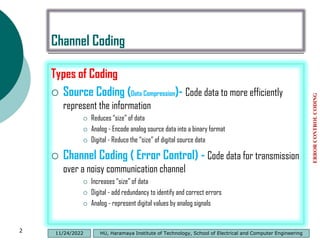
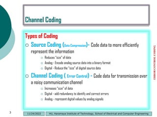
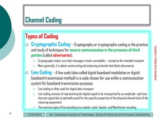
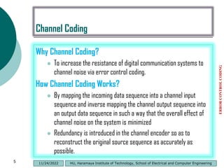
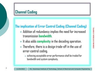
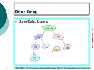
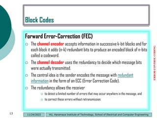
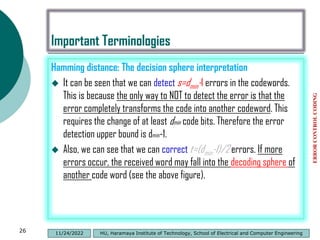
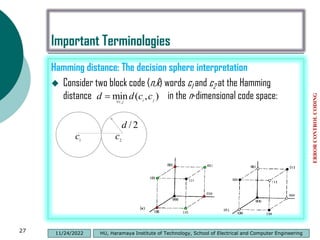
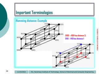
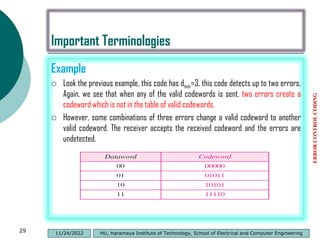
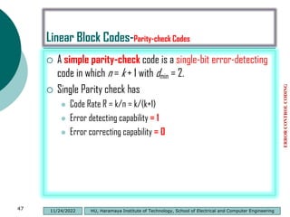
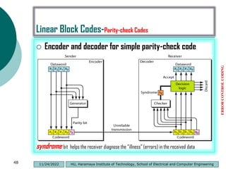
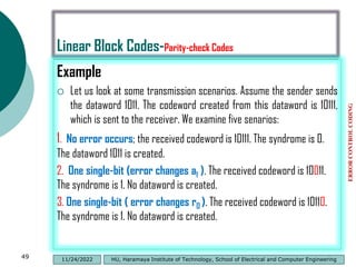
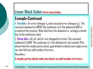
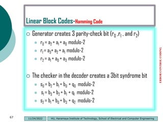
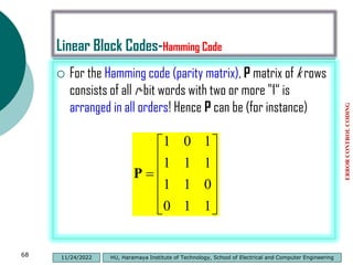
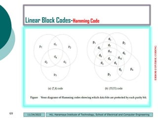
This document discusses channel coding and error control coding. It describes different types of coding including source coding, channel coding, cryptographic coding, and line coding. It then focuses on channel coding, explaining that it works by introducing redundancy to transmitted data to minimize the effects of channel noise. Channel coding allows for error detection and correction at the receiver. Common channel coding techniques are block codes and convolutional codes. Block codes map source data into fixed length codewords while convolutional codes use variable length coding where each source bit influences multiple channel bits.

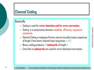

![Binomial Distribution
If the random variable X follows the binomial distribution with parameters
n ∈ ℕ and p ∈ [0,1], The probability of getting exactly k successes in n
independent Bernoulli trials is given by the probability mass function:
The formula can be understood as follows: k successes occur with
probability pk and n − k failures occur with probability (1 − p)n − k.
However, the k successes can occur anywhere among the n trials, and
there are different ways of distributing k successes in a sequence of
n trials.
ERROR
CONTROL
CODING
32 HU, Haramaya Institute of Technology, School of Electrical and Computer Engineering
11/24/2022](https://image.slidesharecdn.com/introductiontochannelcoding-230101205554-f87ab3ca/85/Introduction-to-Channel-Coding-pdf-31-320.jpg)
![Linear Block Codes-Cyclic Codes
Cyclic code is a block code, where the circular shifts of each
codeword gives another word that belongs to the code.
They are error-correcting codes that have algebraic properties that
are convenient for efficient error detection and correction.
Definition:- A code C is cyclic if
C is a linear code;
Any cyclic shift of a codeword is also a codeword,
A cyclic shift of a vector [v0 v1 … vn-2 vn-1] is the vector
[vn-1 v1 … vn-2 ].
Cyclically shifting v, i places to the right is equivalent to
cyclically shifting v, n − i places to the left.
ERROR
CONTROL
CODING
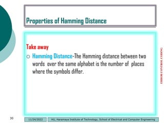
72 HU, Haramaya Institute of Technology, School of Electrical and Computer Engineering
11/24/2022](https://image.slidesharecdn.com/introductiontochannelcoding-230101205554-f87ab3ca/85/Introduction-to-Channel-Coding-pdf-71-320.jpg)
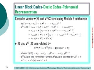
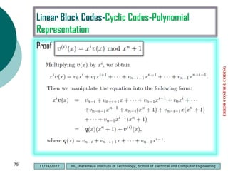
![Linear Block Codes-Cyclic Codes-Polynomial
Representation
Polynomial representation of vectors
For every vector v=[v0 v1 … vn-2 vn-1] there is a polynomial
Let v(i) be the vector resulting from i cyclic shifts on v
ERROR
CONTROL
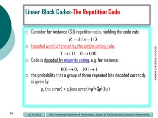
CODING
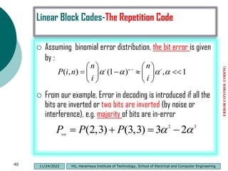
73 HU, Haramaya Institute of Technology, School of Electrical and Computer Engineering
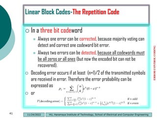
11/24/2022](https://image.slidesharecdn.com/introductiontochannelcoding-230101205554-f87ab3ca/85/Introduction-to-Channel-Coding-pdf-72-320.jpg)
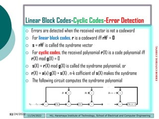
![Linear Block Codes-Cyclic Codes-Error Detection
This correction results in a modified received polynomial, denoted by
r1(x) = r0 + r1x + ・ ・ ・ + rn−2xn−2 + (rn−1 ⊕ en−1)xn−1.
The effect of the error digit en−1 on the syndrome can be achieved by
adding the syndrome of e(x) = xn−1 to s(x).
The syndrome s(1)
1 of r(1)
1 (x) is the remainder resulting from dividing
x[s(x) + xn−1] by the generator polynomial g(x).
ERROR
CONTROL
CODING
101 HU, Haramaya Institute of Technology, School of Electrical and Computer Engineering
11/24/2022](https://image.slidesharecdn.com/introductiontochannelcoding-230101205554-f87ab3ca/85/Introduction-to-Channel-Coding-pdf-100-320.jpg)


![Multiband Transceivers - [Chapter 3] Basic Concept of Comm. Systems](https://cdn.slidesharecdn.com/ss_thumbnails/ch3-150613070933-lva1-app6892-thumbnail.jpg?width=640&height=640&fit=bounds)

![RF Module Design - [Chapter 1] From Basics to RF Transceivers](https://cdn.slidesharecdn.com/ss_thumbnails/rfch1-150613070344-lva1-app6892-thumbnail.jpg?width=640&height=640&fit=bounds)


![RF Module Design - [Chapter 2] Noises](https://cdn.slidesharecdn.com/ss_thumbnails/rfch2-150613070344-lva1-app6892-thumbnail.jpg?width=640&height=640&fit=bounds)