B Y
P rof . B r i j b h u s h a n S h u k l a
S h r e e y a sh C o l l e g e O f E n g i n e e r i n g &
T e c h n o l o g y C h h a t ra pa t i S a m b h aj i n a g a r
Unit 1 :
Introduction to Automobile
Engineering
2.
Introduction to AutomobileEngineering
Automobile engineering, also known as automotive engineering, is a specialized field of
engineering that deals with the design, development, manufacturing, and maintenance of vehicles.
It's a broad discipline that combines elements of mechanical, electrical, electronic, safety, and
software engineering.
A Brief History of Automobile Engineering
The history of automobile engineering is a fascinating journey that spans from steam-powered
carriages to today's highly complex, computer-controlled vehicles. The key milestones include:
The Pioneers (Late 18th & 19th Century)
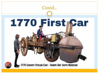
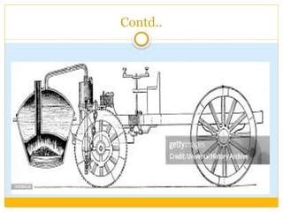
The first self-propelled road vehicles were powered by steam engines. In 1769, French engineer
Nicolas-Joseph Cugnot built a steam-powered tricycle for the French army. While it was slow and
impractical, it was a significant step. However, the true birth of the modern automobile came with
the development of the internal combustion engine.
Contd..
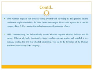
1886: Germanengineer Karl Benz is widely credited with inventing the first practical internal
combustion engine automobile, the Benz Patent-Motorwagen. He received a patent for it, and his
company, Benz & Cie., was the first to begin commercial production of cars.
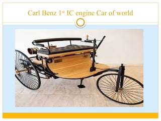
1886: Simultaneously, but independently, another German engineer, Gottlieb Daimler, and his
partner Wilhelm Maybach, developed a faster, gasoline-powered engine and installed it in a
carriage, creating the first four-wheeled automobile. This led to the formation of the Daimler-
Motoren-Gesellschaft (DMG) company.
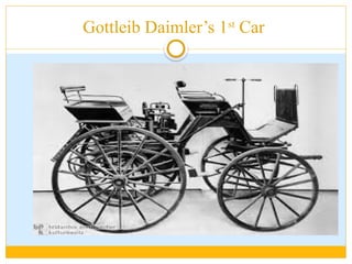
The Age ofMass Production (Early 20th Century)
The early 1900s marked a shift from handcrafted luxury vehicles to mass-produced, affordable
transportation. This revolution was spearheaded by Henry Ford with his introduction of the
assembly line in 1913.
1908: The Ford Model T was introduced, becoming the first car that was truly accessible to the
middle class. Ford's assembly line drastically reduced production time and costs, making the car a
common possession rather than a luxury item.
Innovations: This era also saw the introduction of key mechanical and electrical components,
such as the electric starter (1911), which replaced the hand crank, and the first commercial in-car
radio (1930).
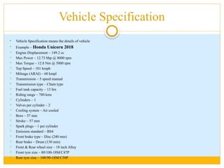
Vehicle Specification
VehicleSpecification means the details of vehicle
Example – Honda Unicorn 2018
Engine Displacement – 149.2 cc
Max Power – 12.73 bhp @ 8000 rpm
Max Torque – 12.8 Nm @ 5000 rpm
Top Speed – 101 kmph
Mileage (ARAI) – 60 kmpl
Transmission – 5 speed manual
Transmission type – Chain type
Fuel tank capacity – 13 ltrs
Riding range – 780 kms
Cylinders – 1
Valves per cylinder – 2
Cooling system – Air cooled
Bore – 57 mm
Stroke – 57 mm
Spark plugs – 1 per cylinder
Emission standard – BS4
Front brake type – Disc (240 mm)
Rear brake – Drum (130 mm)
Front & Rear wheel size – 18 inch Alloy
Front tyre zize – 80/100-18M/C47P
Rear tyre zize – 100/90-18M/C58P
11.
Contd..
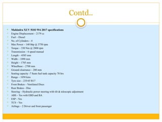
Mahindra XUV5OO W6 2017 specifications
Engine Displacement – 2179 cc
Fuel – Diesel
No. of Cylinders – 4
Max Power – 140 bhp @ 3750 rpm
Torque – 330 Nm @ 2800 rpm
Transmission – 6 speed manual
Length – 4585 mm
Width – 1890 mm
Height – 1785 mm
Wheelbase – 2700 mm
Ground clearrance – 200 mm
Seating capacity -7 Seats fuel tank capacity 70 ltrs
Range – 1050 kms
Tyre size – 235/65 R17
Front Brakes – Ventilated Discs
Rear Brakes - Disc
Steering – Hydraulic power steering with tilt & telescopic adjustment
ABS – Yes with EBD and BA
ESP – Yes
TCS – Yes
Airbags – 2 Driver and front passenger
12.
Vehicle Classification
Vehicleclassification is the process of grouping motor vehicles based on shared characteristics. This is a
crucial practice for various purposes, including traffic management, tax policies, and vehicle
manufacturing standards. Classification systems vary by country and organization, but they generally
rely on a combination of factors.
Common Classification Criteria
Vehicle classification systems typically use one or more of the following criteria:
Function and Purpose: This is a fundamental way to classify vehicles, focusing on their primary use.
Passenger Vehicles: Designed to transport people. This includes sedans, hatchbacks, SUVs, and
minivans.
Commercial Vehicles: Designed for carrying goods or paying passengers. This category includes
trucks, buses, vans, and taxis.
Special Purpose Vehicles: Vehicles designed for a specific task, such as fire engines, ambulances,
police cars, and construction equipment.
13.
Contd..
Axle andWheel Configuration : This is a detailed classification system often used by
transportation agencies like the Federal Highway Administration (FHWA) in the United States to
manage highway usage and infrastructure. Vehicles are categorized by the number of axles and
whether they are single units or combined with trailers.
Motorcycles: Typically two- or three-wheeled vehicles.
Passenger Cars: Usually have two axles and four tires.
Single-Unit Trucks: Vehicles on a single frame, classified by the number of axles (e.g., 2-axle, 3-
axle, etc.).
Combination Trucks: Consist of a tractor unit and one or more trailers. These are classified by the
total number of axles in the combination (e.g., a 5-axle single-trailer truck).
14.
Contd..
Body Styleand Design 🎨: This system is more common for passenger vehicles and is used for
marketing and consumer purposes.
Sedan: A car with a separate trunk and a fixed roof, typically with four doors.
Hatchback: A car with a hatchback door that swings upward, and a shared passenger and cargo
space.
SUV (Sport Utility Vehicle): A vehicle with elevated ground clearance and a station wagon body,
often with all-wheel drive or four-wheel drive.
Coupe: A two-door car with a fixed roof and a sleek, sporty design.
Convertible: A car with a flexible, removable roof.
15.
Chasis Layout
Achassis is the foundational framework of a vehicle, often referred to as its "skeleton." It's the load-
bearing structure that supports the engine, transmission, suspension, and other essential components.
The chassis layout is the specific design and arrangement of this framework. Different layouts are
used depending on the vehicle's intended purpose, whether it's for performance, off-roading, or
everyday commuting.
Main Types of Chassis Layouts
There are several primary types of chassis layouts, each with its own advantages and disadvantages:
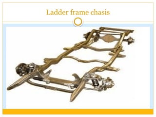
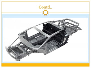
1. Ladder Frame Chassis
Description: This is one of the oldest and simplest designs, named for its resemblance to a ladder. It
consists of two long, parallel side rails connected by several cross members. The vehicle's body is
then bolted on top of this separate frame. This is known as "body-on-frame" construction.
16.
Contd..
Pros:
Durabilityand Strength: It's incredibly strong and can handle heavy loads and rough terrain.
Easy to Manufacture: Simple design makes it relatively easy and cost-effective to produce.
Versatility: The separate body and frame allow for a variety of body styles to be built on the
same chassis.
Cons:
Heavy: This design adds significant weight to the vehicle, which can negatively impact fuel
efficiency and handling.
Poor Torsional Rigidity: It can twist and flex under stress, which can compromise handling
and ride comfort, especially during cornering.
Common Applications: This layout is predominantly used in vehicles that require a
high degree of strength and durability, such as trucks, SUVs with off-roading
capabilities (e.g., Toyota Fortuner, Mahindra Thar), and large commercial
vehicles.
Contd..
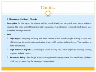
2. Monocoque (Unibody)Chassis
Description: In this layout, the chassis and the vehicle's body are integrated into a single, cohesive
structure. The entire shell of the car is a load-bearing unit. This is the most common type of chassis used
in modern passenger vehicles.
Pros:
Lightweight: Integrating the body and frame reduces overall vehicle weight, leading to better fuel
efficiency and the single-piece construction is very stiff, resisting twisting forces. This translates to
better herformance.
High Torsional Rigidity: A monocoque chassis is very stiff, which improves handling, steering
response, and ride comfort.
Enhanced Safety: The design allows for engineered crumple zones that absorb and dissipate
crash energy, protecting the passenger compartment.
19.
Contd..
Cons:
o Complexand Expensive Repairs: Because the body and frame are a single unit, damage to one part
of the structure can compromise the entire shell. This makes repairs more complex, time-consuming,
and costly, as opposed to a traditional body-on-frame design where individual parts can be more
easily replaced.
o Limited Off-Road Capability: The monocoque design is generally not as robust for extreme off-
road conditions. It lacks the durability and flexibility of a traditional ladder frame, which can handle
the twisting and flexing of rough terrains better. While some modern SUVs with a unibody are
capable of light off-roading, they are not suited for heavy-duty abuse.
o Lower Towing and Load-Carrying Capacity: The lighter, integrated structure of a
monocoque is not designed to handle the same heavy loads as a body-on-frame chassis. This
makes them less ideal for vehicles that are required to tow trailers or carry significant cargo.
20.
Contd..
o Less Flexibilityfor Modifications: The all-in-one structure of a
monocoque chassis leaves little room for significant modifications without
affecting the vehicle's overall integrity. This is a disadvantage for enthusiasts
who want to extensively customize their vehicles, for example, by adding
suspension lifts or heavy-duty components
Applications: This is the most prevalent chassis type in modern passenger vehicles, including
sedans, hatchbacks, crossovers, and even many SUVs. Examples include the Maruti Swift, Honda
City, and Tata Nexon.
Contd..
3. BackboneChassis
Structure: A single, strong tubular spine runs down the center of the vehicle, connecting the front and
rear suspension. The engine, transmission, and body panels are all attached to this central spine.
Key Features:
High Rigidity: The central spine provides excellent resistance to bending and twisting forces.
Good Protection for Drive-train: The driveshaft and other vulnerable components are often
enclosed within the backbone tube, protecting them from damage.
Unique Design: Allows for a very low and compact profile.
Applications: This design is less common and is typically used in specialized vehicles like sports cars,
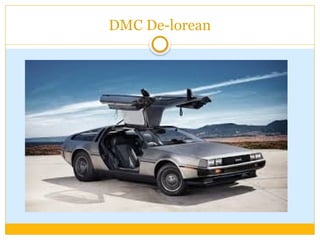
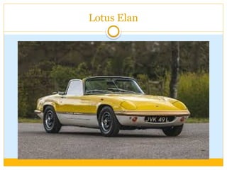
kit cars, and some off-road vehicles. Famous examples include the Lotus Elan and DMC DeLorean.
Contd..
4 . TubularSpace Frame Chassis
Structure: A three-dimensional lattice of interconnected tubes, typically made of steel or aluminum, that
form a rigid cage-like structure. The body panels are non-structural and are simply attached to this frame.
Key Features:
Extreme Rigidity and Lightweight: Offers an incredible strength-to-weight ratio, making it the top
choice for high-performance applications.
Excellent Safety: The rigid cage provides a very strong passenger cell, offering superior crash
protection.
Complex and Expensive: The manufacturing process is complex, requiring precise welding and is
not suitable for mass production.
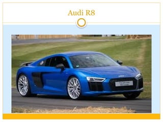
Applications: Almost exclusively found in high-performance sports cars, supercars, and race cars where
maximum rigidity and minimum weight are paramount. Examples include the Audi R8 and Formula 1
race cars.
Main Components ofAutomobile
An automobile is a complex machine made up of thousands of parts, but these components can be
grouped into several major systems that work together to make the vehicle function. Here are the
main components of an automobile, broken down by system:
1. Chassis and Body
This is the foundation of the vehicle.
Chassis/Frame: The main structural framework that supports all other components, including the
engine, transmission, body, and suspension. It's the skeleton of the car. As discussed in the previous
answer, it can be a unibody (monocoque), ladder frame, backbone, or space frame.
Body: The outer shell of the vehicle, including the panels, doors, hood, and roof. It's designed for
aerodynamics, aesthetics, and passenger protection.
Steering System: Allows the driver to control the direction of the vehicle. Key components include
the steering wheel, steering column, and steering gear (e.g., rack and pinion).
28.
Contd..
2. Engine (PowerUnit)
This is the heart of the car, converting chemical energy from fuel into mechanical energy.
Engine Block: The main casting that houses the cylinders, pistons, and crankshaft.
Pistons: Reciprocating components that move up and down within the cylinders, driven by the combustion
of fuel.
Crankshaft: Converts the linear motion of the pistons into rotational motion.
Cylinder Head: Sits on top of the engine block and contains the valves, camshaft, and spark plugs (in
gasoline engines).
Valves: Regulate the flow of air-fuel mixture into the cylinders and exhaust gases out.
Fuel System: Includes the fuel tank, fuel pump, fuel lines, and fuel injectors or carburetor, which deliver
fuel to the engine.
Cooling System: A system (usually with a radiator, water pump, and coolant) that prevents the engine from
overheating.
Lubrication System: Circulates oil to reduce friction between moving parts and prevent wear.
29.
Contd..
3. Drivetrain/Transmission System
This system transmits the power from the engine to the wheels.
Clutch (Manual Transmission): A component that engages and disengages the engine from the
transmission, allowing the driver to change gears.
Transmission/Gearbox: A series of gears that changes the ratio between engine speed and wheel
speed. This allows the vehicle to accelerate from a standstill and travel at high speeds.
Driveshaft (Propeller Shaft): A rotating shaft that carries power from the transmission to the
differential in rear-wheel-drive and all-wheel-drive vehicles.
Differential: A device that allows the wheels on the same axle to rotate at different speeds, which
is essential for turning.
Axles: The shafts on which the wheels are mounted.
Wheels and Tires: The components that make contact with the road, providing traction and
support.
30.
Contd..
4. Suspension andBraking Systems
These systems are crucial for safety, control, and comfort.
Suspension System: Consists of springs, shock absorbers (dampers), and linkages. It's designed to
absorb bumps and vibrations from the road, providing a smooth ride and keeping the tires in
contact with the road for optimal control.
Braking System: The components that slow and stop the vehicle. This includes the brake pedal,
master cylinder, brake lines, calipers, and rotors (or drums). Modern cars also have an Anti-lock
Braking System (ABS) to prevent wheel lock-up during hard braking.
31.
Contd..
5. Electrical System
This system provides the necessary power and controls for the car's various functions.
Battery: Provides the initial power to start the engine and powers accessories when the engine is
off.
Alternator: Charges the battery and provides electricity to the vehicle's electrical systems while
the engine is running.
Starter Motor: An electric motor that uses battery power to crank the engine and start it.
Wiring Harness: A complex network of wires and connectors that links all the electrical
components.
Ignition System: Creates the spark needed to ignite the fuel-air mixture in the engine's cylinders.
Electronic Control Unit (ECU): The "brain" of the car, a computer that controls and monitors
various engine and vehicle functions.
32.
Contd..
6. Safety Systems
Modern vehicles are equipped with numerous features to protect occupants and prevent accidents.
Passive Safety: Components designed to protect occupants during a crash.
Seatbelts: Restrain occupants and distribute forces in a collision.
Airbags: Inflate rapidly to cushion occupants during an impact.
Crumple Zones: Designed to deform and absorb crash energy.
Active Safety: Components and systems that help prevent a crash from occurring.
Anti-lock Braking System (ABS)
Traction Control System (TCS): Prevents wheel spin during acceleration.
Electronic Stability Control (ESC): Helps the driver maintain control of the vehicle during
extreme steering maneuvers.
33.
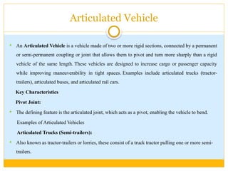
Articulated Vehicle
AnArticulated Vehicle is a vehicle made of two or more rigid sections, connected by a permanent
or semi-permanent coupling or joint that allows them to pivot and turn more sharply than a rigid
vehicle of the same length. These vehicles are designed to increase cargo or passenger capacity
while improving maneuverability in tight spaces. Examples include articulated trucks (tractor-
trailers), articulated buses, and articulated rail cars.
Key Characteristics
Pivot Joint:
The defining feature is the articulated joint, which acts as a pivot, enabling the vehicle to bend.
Examples of Articulated Vehicles
Articulated Trucks (Semi-trailers):
Also known as tractor-trailers or lorries, these consist of a truck tractor pulling one or more semi-
trailers.
34.
Contd..
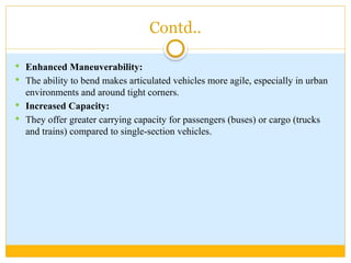
Enhanced Maneuverability:
The ability to bend makes articulated vehicles more agile, especially in urban
environments and around tight corners.
Increased Capacity:
They offer greater carrying capacity for passengers (buses) or cargo (trucks
and trains) compared to single-section vehicles.
35.
Contd..
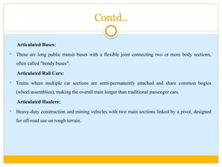
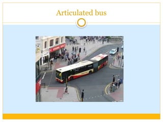
Articulated Buses:
Theseare long public transit buses with a flexible joint connecting two or more body sections,
often called "bendy buses".
Articulated Rail Cars:
Trains where multiple car sections are semi-permanently attached and share common bogies
(wheel assemblies), making the overall train longer than traditional passenger cars.
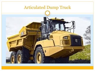
Articulated Haulers:
Heavy-duty construction and mining vehicles with two main sections linked by a pivot, designed
for off-road use on rough terrain.
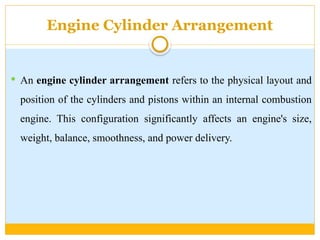
Engine Cylinder Arrangement
An engine cylinder arrangement refers to the physical layout and
position of the cylinders and pistons within an internal combustion
engine. This configuration significantly affects an engine's size,
weight, balance, smoothness, and power delivery.
39.
Common Cylinder Arrangements
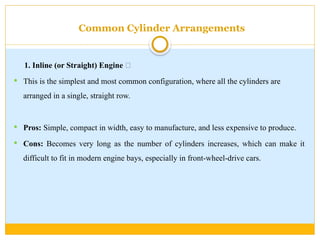
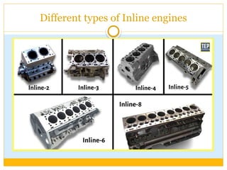
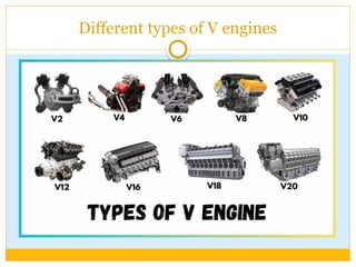
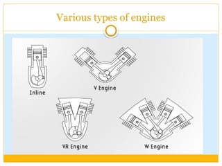
1.Inline (or Straight) Engine 🚗
This is the simplest and most common configuration, where all the cylinders are
arranged in a single, straight row.
Pros: Simple, compact in width, easy to manufacture, and less expensive to produce.
Cons: Becomes very long as the number of cylinders increases, which can make it
difficult to fit in modern engine bays, especially in front-wheel-drive cars.
Contd..
2. V-Engine (V)
A V-engine arranges cylinders in two banks that form a "V" shape when viewed
from the front. The two banks share a common crankshaft.
Common Use: V6, V8, and V12 engines are prevalent in performance cars, trucks, and
luxury vehicles due to their compact length.
Pros: Shorter and more rigid than inline engines with the same number of cylinders,
which makes them easier to package.
Cons: More complex and expensive to manufacture, requiring two cylinder heads and
a more complicated design.
Contd..
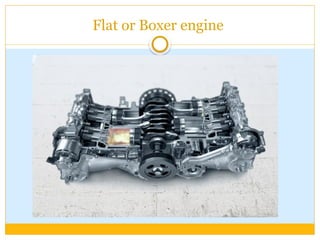
3. Flat (F)or Boxer (B)
A flat or boxer engine has its cylinders arranged in two banks lying flat on opposite sides
of a central crankshaft, forming a 180° "V" shape. The pistons in opposing cylinders move
simultaneously inward and outward, resembling a boxer's fists.
Common Use: Best known for their use in Subaru and Porsche cars, as well as in some
motorcycles and small aircraft.
Pros: A very low center of gravity, which improves vehicle handling. The opposing motion
of the pistons provides excellent primary and secondary balance, resulting in a very smooth
engine.
Cons: Very wide, which can create packaging and maintenance challenges. They require
two cylinder heads and two separate exhaust systems, increasing cost and complexity.
Contd..
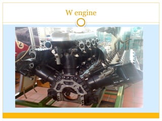
4. W-Engine (W)
A W-engine is an exotic and rare configuration that consists of three or four banks of
cylinders sharing a single crankshaft, resembling a "W" shape.
Common Use: Primarily found in high-end, luxury, and hyper-performance vehicles,
such as those from Bugatti and Volkswagen.
Pros: Extremely short and compact for the high number of cylinders they contain,
allowing for massive displacement and power in a relatively small space.
Cons: Exceptionally complex, heavy, and expensive to design and manufacture.
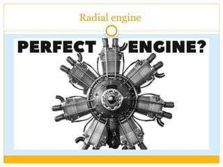
Radial engine
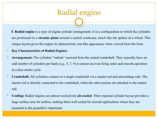
5. Radialengine is a type of engine cylinder arrangement. It is a configuration in which the cylinders
are positioned in a circular plane around a central crankcase, much like the spokes of a wheel. This
unique layout gives the engine its characteristic star-like appearance when viewed from the front
Key Characteristics of Radial Engines
Arrangement: The cylinders "radiate" outward from the central crankshaft. They typically have an
odd number of cylinders per bank (e.g., 5, 7, 9) to ensure an even firing order and smooth operation
in a four-stroke cycle.
Crankshaft: All cylinders connect to a single crankshaft via a master rod and articulating rods. The
master rod is directly connected to the crankshaft, while the other pistons are attached to the master
rod.
Cooling: Radial engines are almost exclusively air-cooled. Their exposed cylinder layout provides a
large surface area for airflow, making them well-suited for aircraft applications where they are
mounted in the propeller's slipstream.
49.
Contd..
Why RadialEngines are Unique
Unlike inline, V, or flat engines, which are typically used in cars and trucks, radial engines
are most famously associated with aircraft. They were the predominant engine type for
many propeller-driven planes, particularly from the 1920s to the 1950s.
Advantages:
Power-to-Weight Ratio: They have a short, rigid crankshaft, which makes them lighter and
more compact longitudinally than other engine types of comparable power.
Reliability: Their simple air-cooled design eliminated the need for complex liquid-cooling
systems, making them more tolerant of combat damage and easier to maintain in the field.
50.
Contd..
Disadvantages:
Drag:Their large, circular frontal area creates significant aerodynamic drag, which
limited the top speed of the aircraft they powered.
Visibility: The sheer size of the engine can obstruct a pilot's view directly over the
nose.
Vibration: Lot of vibration while running
Power requirements inAE
Powering Progress: Understanding Automotive
Power Requirements
Automobiles, whether traditional internal combustion engine (ICE) vehicles
or modern electric vehicles (EVs), have diverse and increasing power
requirements that stem from propulsion, auxiliary systems, and the ever-
expanding array of electronic features. The fundamental power needed for a
vehicle to move is influenced by factors like speed, weight, aerodynamic drag,
and rolling resistance. However, this is just one piece of the complex energy
puzzle.
53.
Contd..
Propulsion Power:The Driving Force
The primary power requirement is, of course, for propulsion. This is the force needed to overcome various
resistances and accelerate the vehicle.
Aerodynamic Drag: This force increases with the square of the vehicle's speed and is a significant factor at
higher velocities. It's influenced by the vehicle's shape and frontal area.
Rolling Resistance: This arises from the deformation of tires as they roll over the road surface and is
influenced by tire pressure, type, and road surface.
Gradient Resistance: This is the force needed to move the vehicle uphill, directly related to the vehicle's
weight and the steepness of the incline.
Inertial Forces: These are required for acceleration, overcoming the vehicle's mass and rotational inertia of
its components.
The engine or electric motor must generate enough power to counteract these forces. For instance,
maintaining a constant speed of 90 km/h on a flat surface with typical resistances might require around 19
kW of engine power. Accelerating the vehicle demands significantly more power.
54.
Contd..
Electrical PowerConsumption: The Growing Demand
Beyond propulsion, modern automobiles are increasingly reliant on electrical systems, leading to a
substantial and growing electrical power demand. This demand is met by the vehicle's alternator
(in ICE vehicles) or battery and power electronics (in EVs).
Key electrical consumers include:
Lighting: Headlights (LEDs can use around 50W, while older halogen systems might exceed
100W for the whole vehicle), taillights, brake lights, and interior lighting.
Climate Control: HVAC systems can draw significant power, with air conditioning systems
potentially adding a load of 500W. Seat heaters can range from 100-200W.
Infotainment and Electronics: Audio systems, navigation, and various sensors and control units
(like Engine Control Units - ECUs) contribute to the electrical load, with ECUs alone potentially
consuming up to 200W.
55.
Contd..
Power Accessories:Power windows, power seats, sunroofs, and central locking systems utilize
motors that draw power, though often intermittently.
Driver Assistance Systems (ADAS): Advanced features like lane assist, adaptive cruise control,
and parking sensors require dedicated power.
Starter Motor: In ICE vehicles, the starter motor is the most power-hungry component, drawing
substantial current for a short duration to initiate engine rotation.
In modern vehicles, the cumulative electrical load can be significant, with low-voltage battery
systems sometimes needing to supply currents between 400A and 800A during peak demand.
56.
Tractive Efforts andVehicle performance curves
Tractive effort and vehicle performance curves are crucial tools used in automotive engineering to
understand and predict how a vehicle will perform under various conditions. They help in
designing powertrains, transmissions, and overall vehicle dynamics.
Tractive Effort
Tractive effort is the force available at the contact point between the driving wheels and the road
surface that propels the vehicle forward. It's essentially the "push" the vehicle can generate to
overcome resistance and accelerate.
Calculation: Tractive effort is generally calculated by multiplying the engine's torque by the total
gear ratio (including transmission and final drive ratios), then by the drivetrain efficiency, and
finally dividing by the rolling radius of the tires.
Tractive Effort = Engine Torque×Total Gear Ratio×Drivetrain Efficiency/Tire Rolling Radius
57.
Contd..
Factors Influencing TractiveEffort:
Engine Torque: The inherent twisting force produced by the engine.
Gear Ratio: Lower gears provide higher tractive effort for acceleration, while higher gears
provide lower tractive effort for higher speeds.
Drivetrain Efficiency: Losses in the transmission, differential, and axles reduce the effective
tractive effort.
Tire Rolling Radius: A larger radius generally means less tractive effort for a given torque.
Traction Limit: The maximum tractive effort a vehicle can exert without its drive wheels
slipping. This is determined by the friction between the tires and the road surface, and the weight
on the drive wheels.
58.
Contd..
Vehicle Performance Curves
Vehicle performance curves are graphical representations that illustrate the relationship between
various performance parameters, such as tractive effort, speed, power, and resistance. They
provide a comprehensive view of a vehicle's capabilities.
Key Performance Curves:
1. Tractive Effort vs. Vehicle Speed Curve:
This is a fundamental curve that shows the tractive effort a vehicle can produce at different
speeds.
In-gear curves: For each gear, there's a curve showing how tractive effort changes with speed.
As speed increases in a particular gear, tractive effort generally decreases because the engine's
power output is being distributed over a larger rotational distance.
59.
Contd..
Overall TractiveEffort Curve: This curve is formed by plotting the maximum tractive effort
available at each speed, considering all gears. It typically shows a high tractive effort at low speeds
(in lower gears) that decreases as speed increases.
Traction Limit Line: This horizontal line represents the maximum tractive effort the vehicle can
achieve before the tires slip. The actual tractive effort cannot exceed this limit.
2. Power vs. Vehicle Speed Curve:
This curve illustrates the power output of the vehicle at different speeds.
Engine Power Curve: Shows the engine's power output across its RPM range.
Wheel Power Curve: Depicts the power delivered to the wheels after drivetrain losses.
The relationship between power and tractive effort is critical: Power = Tractive Effort × Speed.
This means that at a given speed, higher tractive effort equates to higher power.
60.
Contd..
3. Resistance vs.Vehicle Speed Curve:
This curve shows the forces that oppose the vehicle's motion, which increase with speed.
Aerodynamic Drag: Increases approximately with the square of the speed.
Rolling Resistance: Primarily due to tire deformation and friction with the road.
Gradient Resistance: The force required to climb an incline.
61.
Contd..
How TheyAre Used
Tractive effort and vehicle performance curves are vital for:
Vehicle Design and Optimization:
Transmission Design: Engineers use these curves to determine the optimal number of gears,
gear ratios, and shift points to ensure the engine operates within its most efficient and powerful
range across various speeds.
Engine Selection: They help in selecting an engine with appropriate torque and power
characteristics to meet performance targets.
Performance Prediction: They allow for the accurate prediction of a vehicle's acceleration,
top speed, and gradeability (ability to climb hills).
62.
Contd..
Performance Analysis:
Comparing Vehicles: These curves enable a direct comparison of the performance capabilities of
different vehicles.
Troubleshooting: They can help diagnose performance issues by comparing actual performance
to theoretical curves.
Marketing and Consumer Information:
Simplified versions of these curves or the data derived from them are used to communicate a
vehicle's performance to potential buyers.
In essence, these curves provide a roadmap of a vehicle's capabilities, enabling engineers to design
efficient, powerful, and well-performing automobiles.