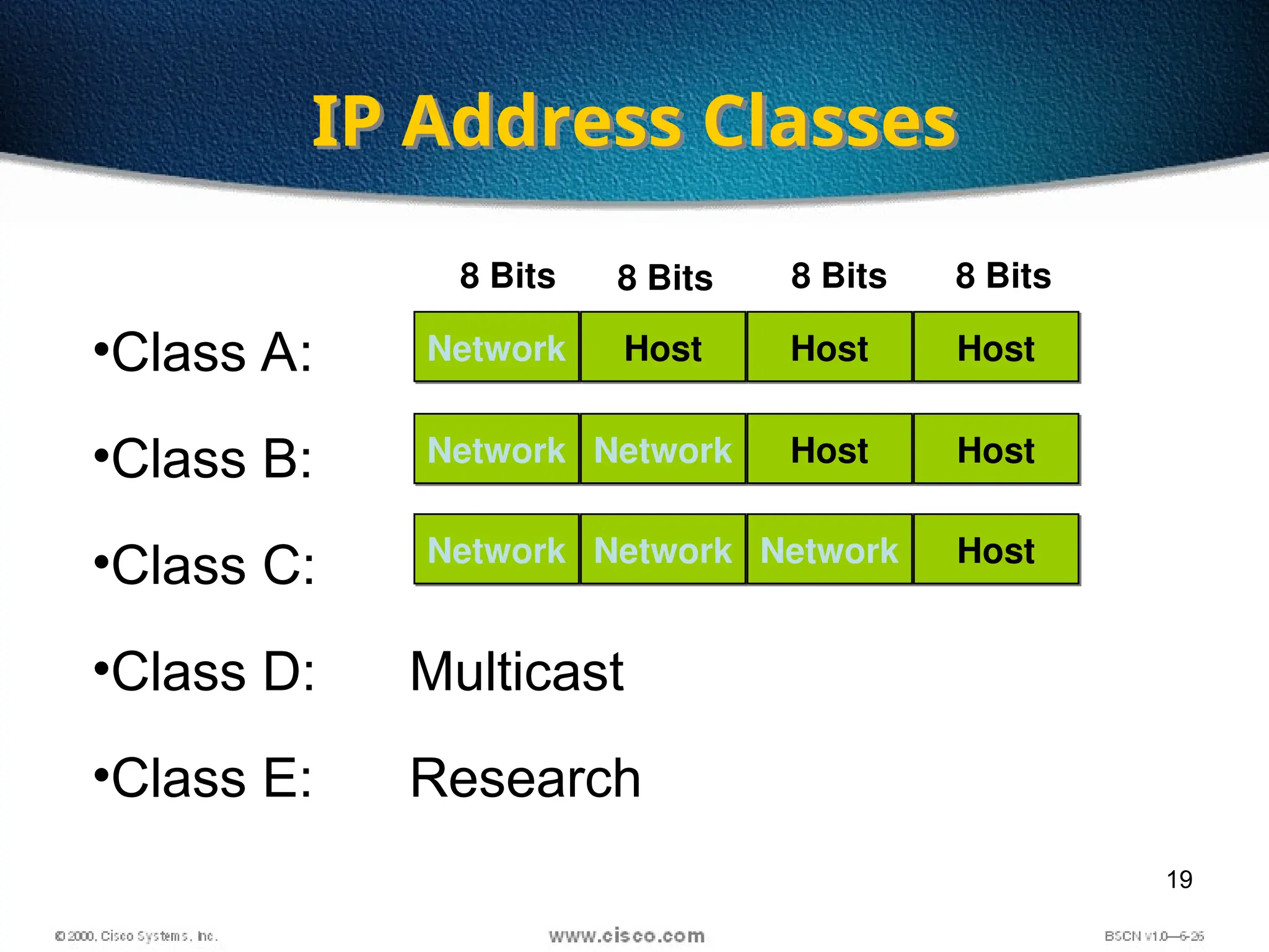
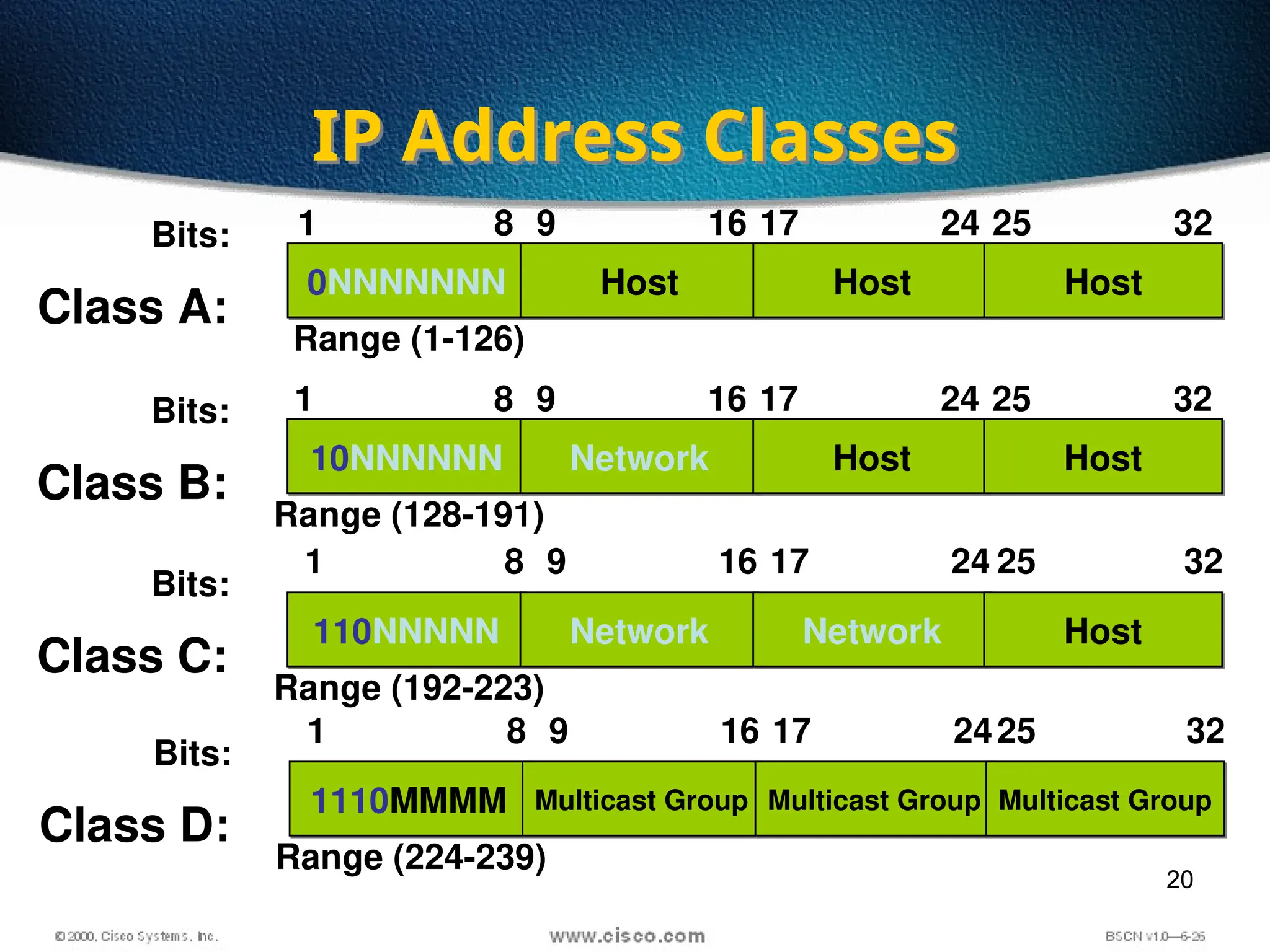
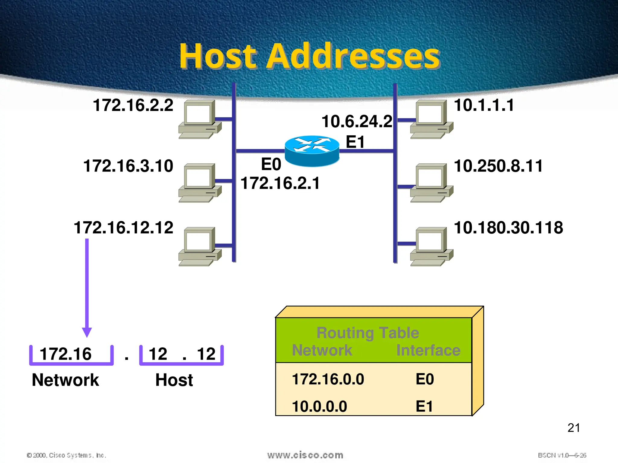
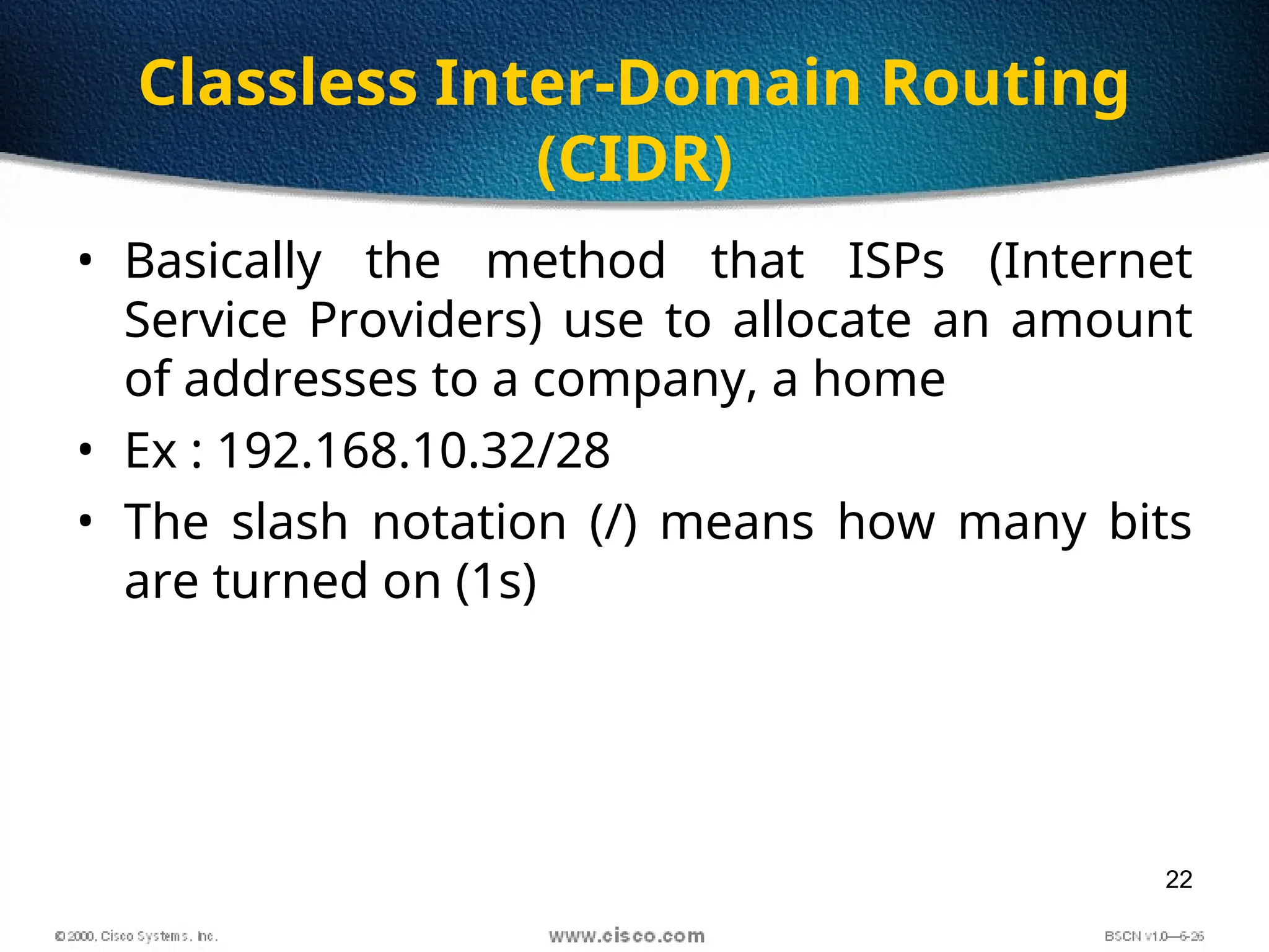
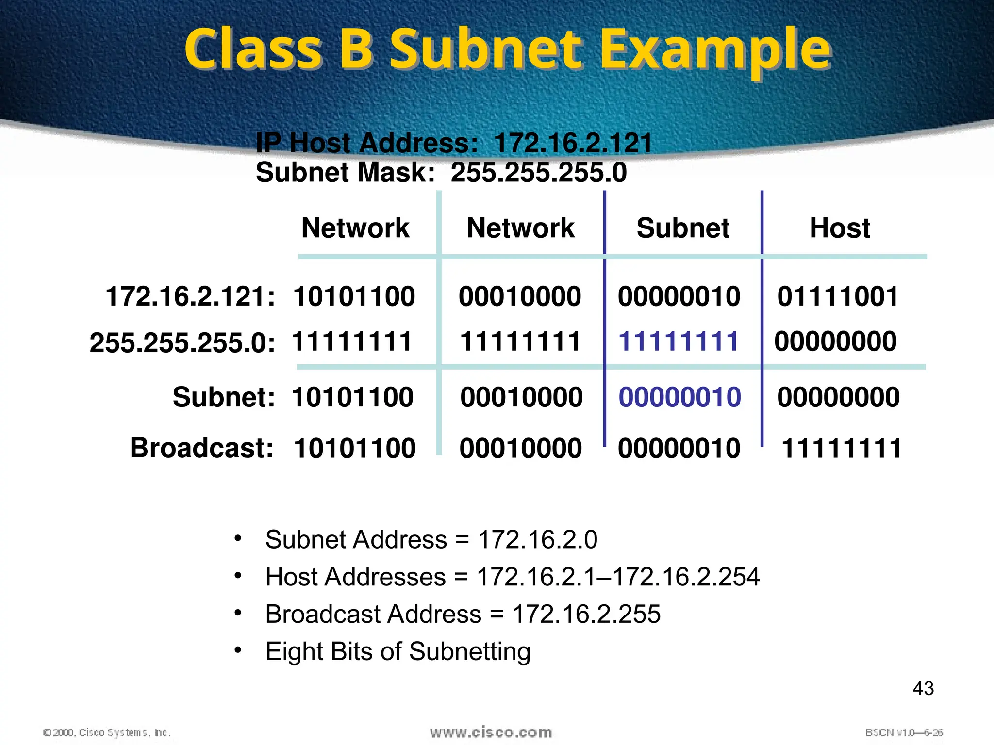
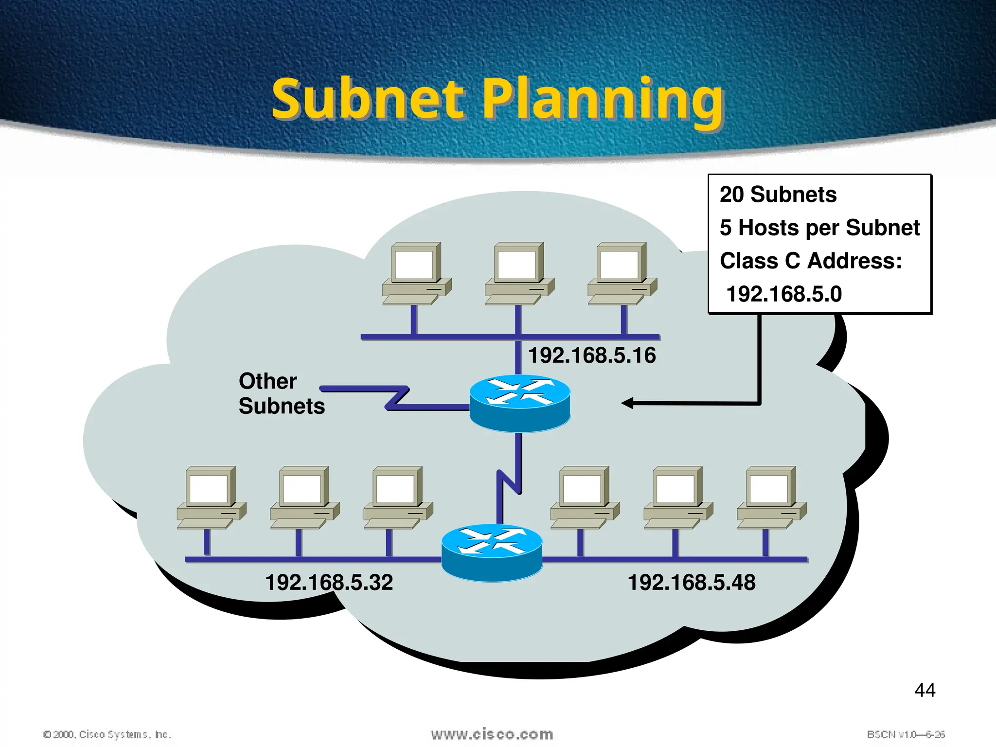
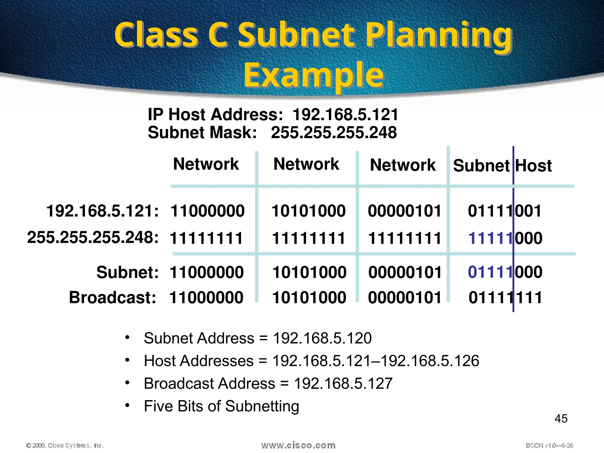
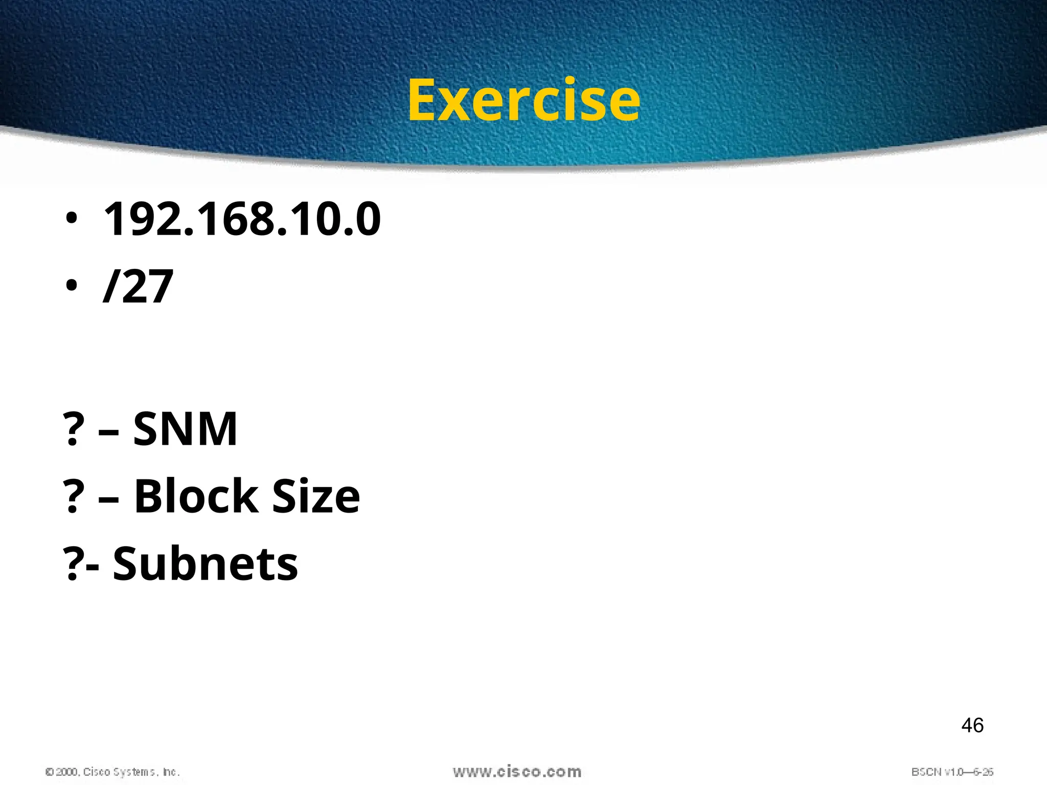
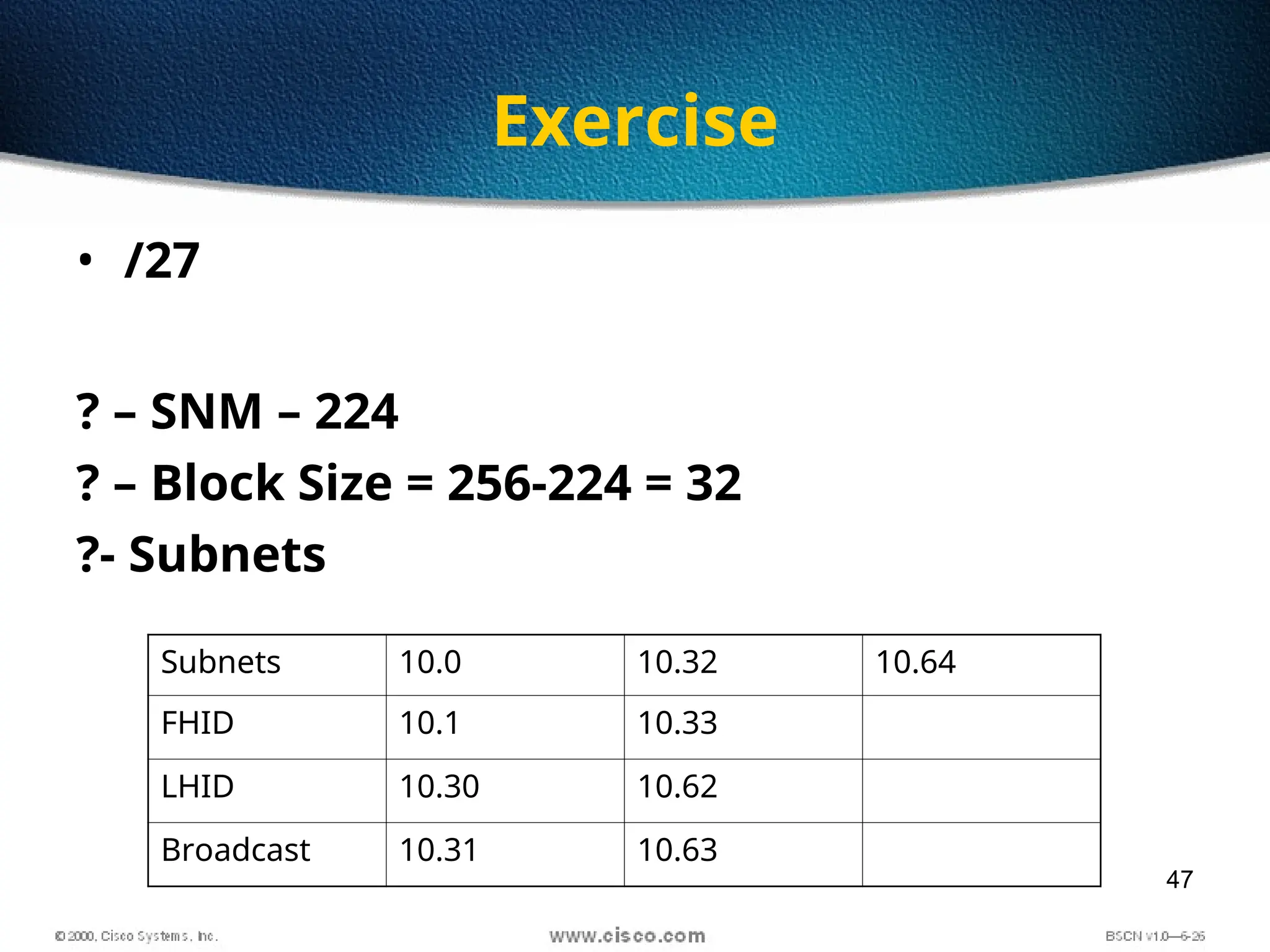
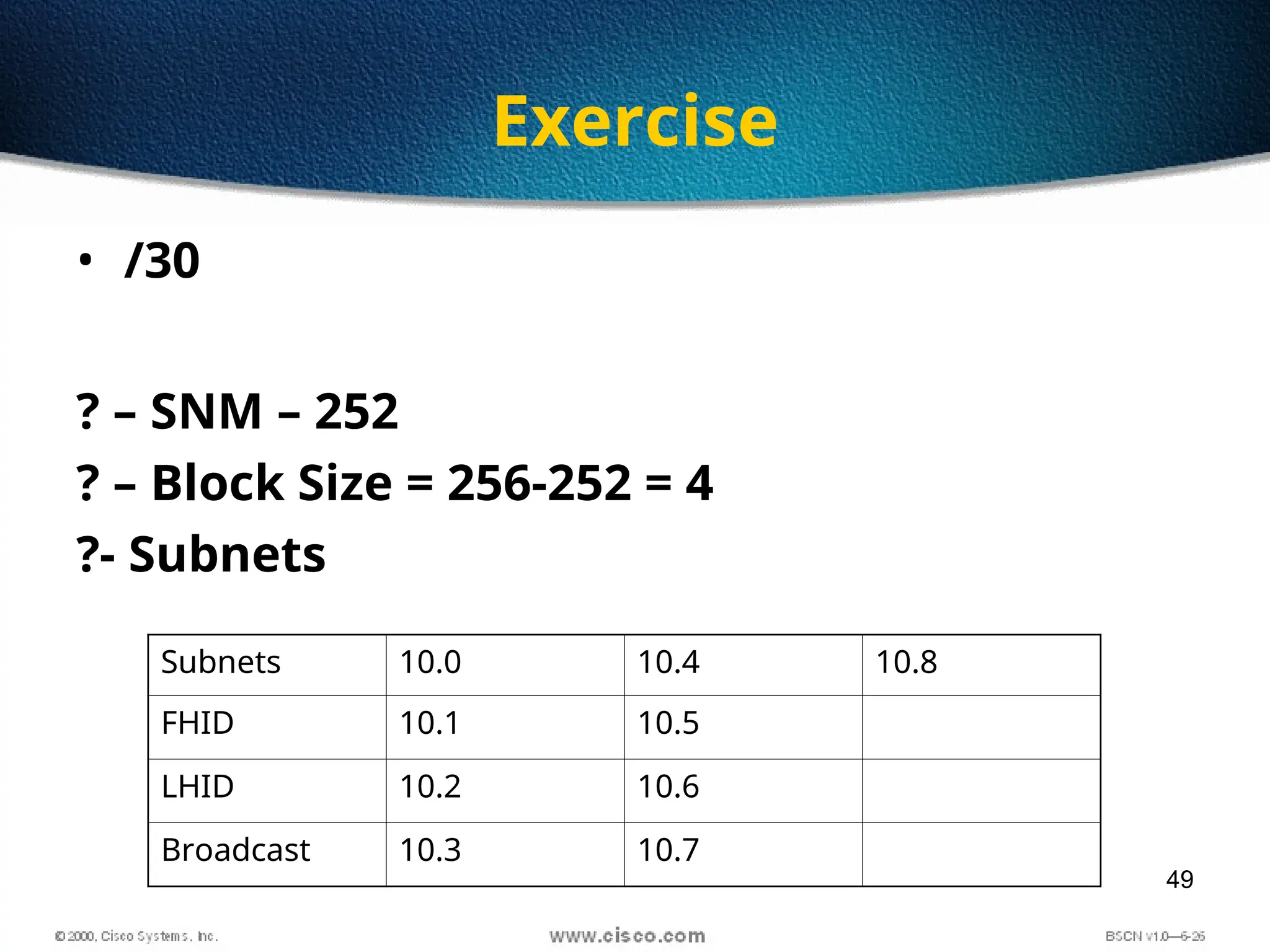
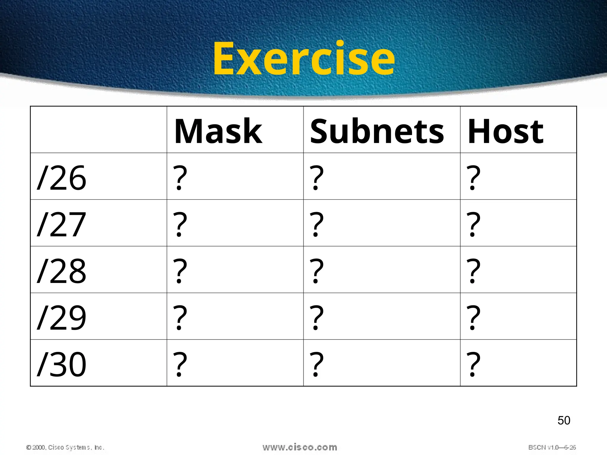
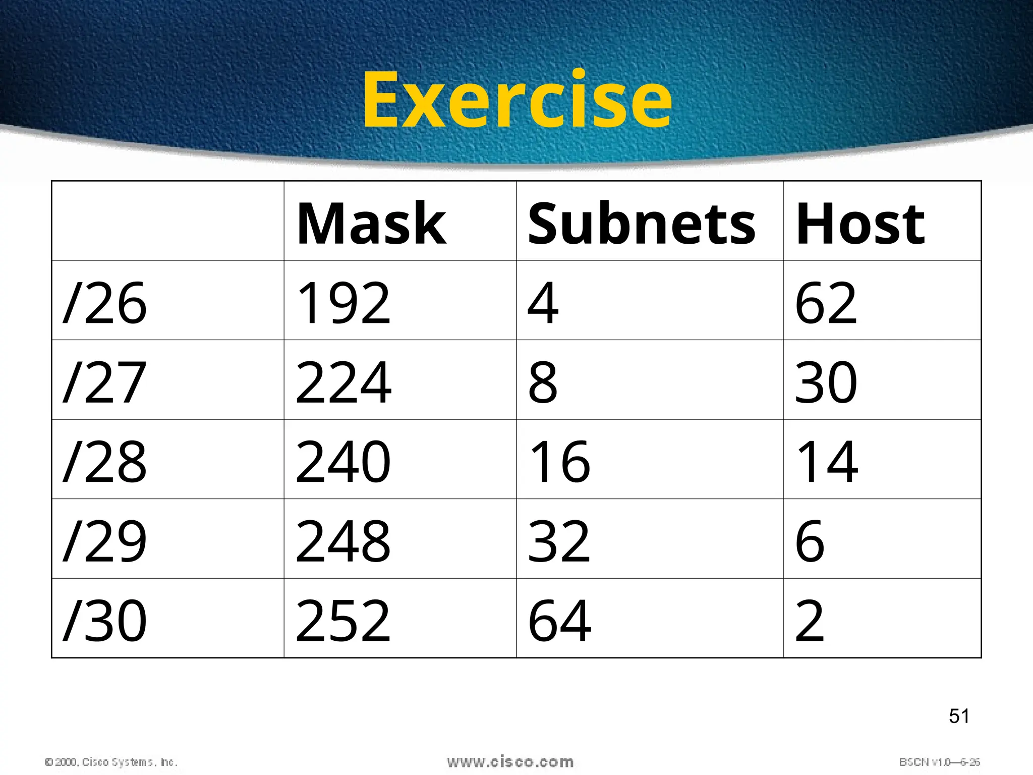
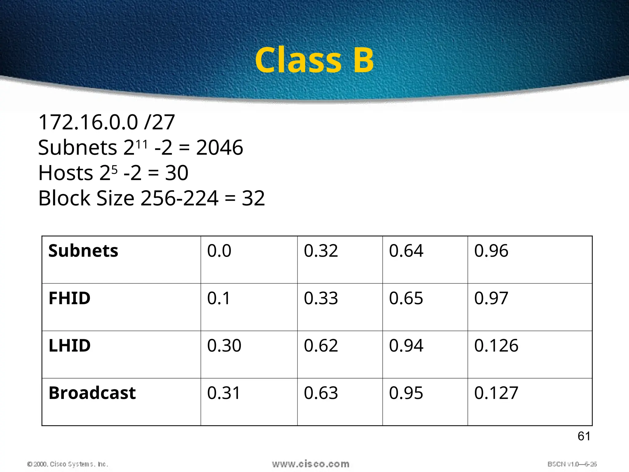
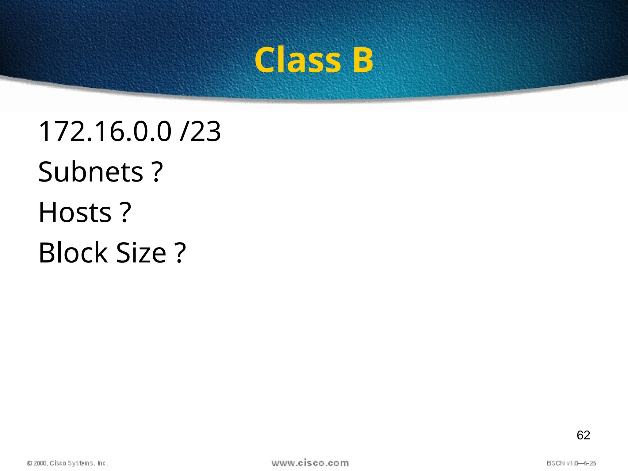
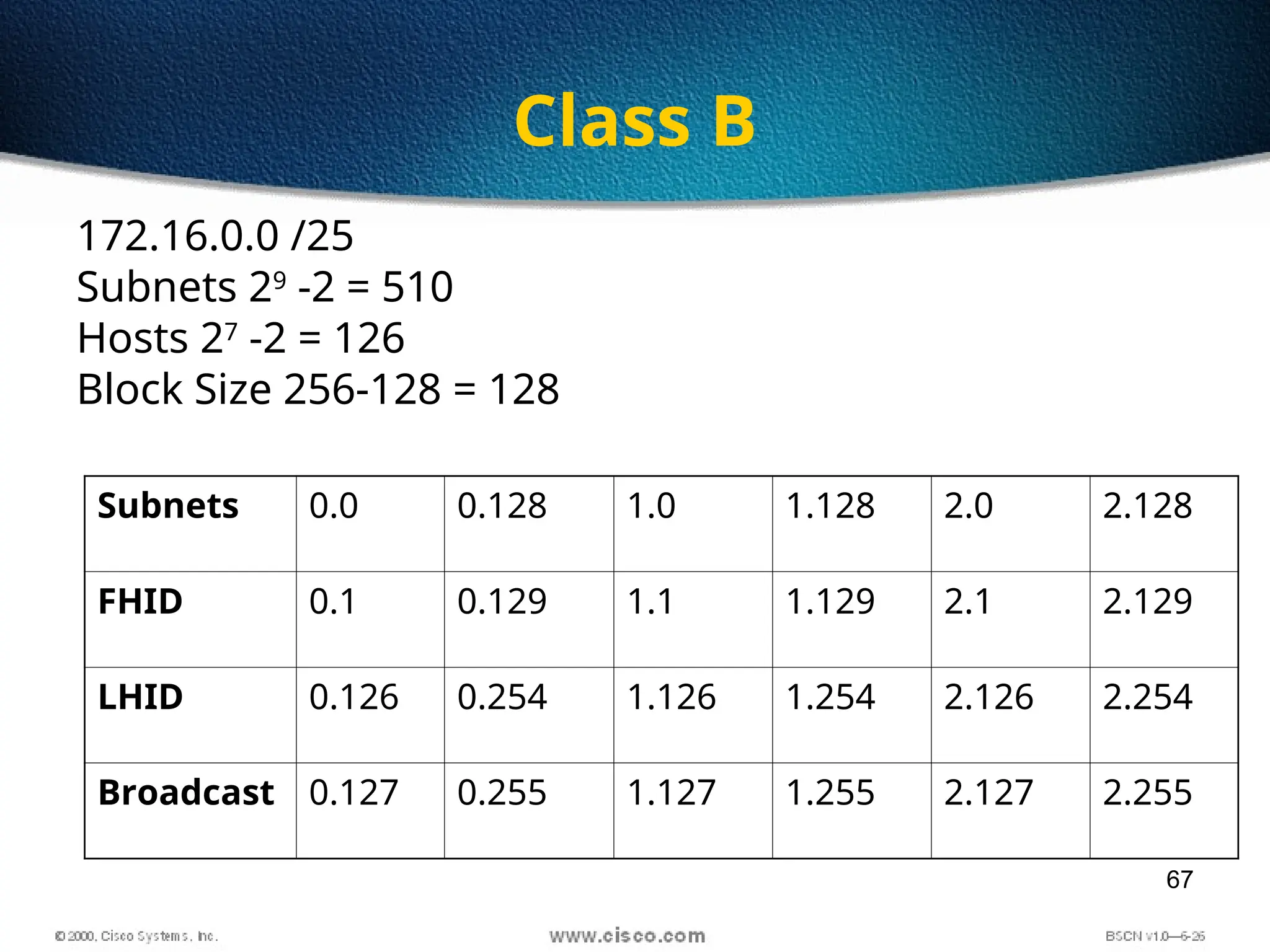
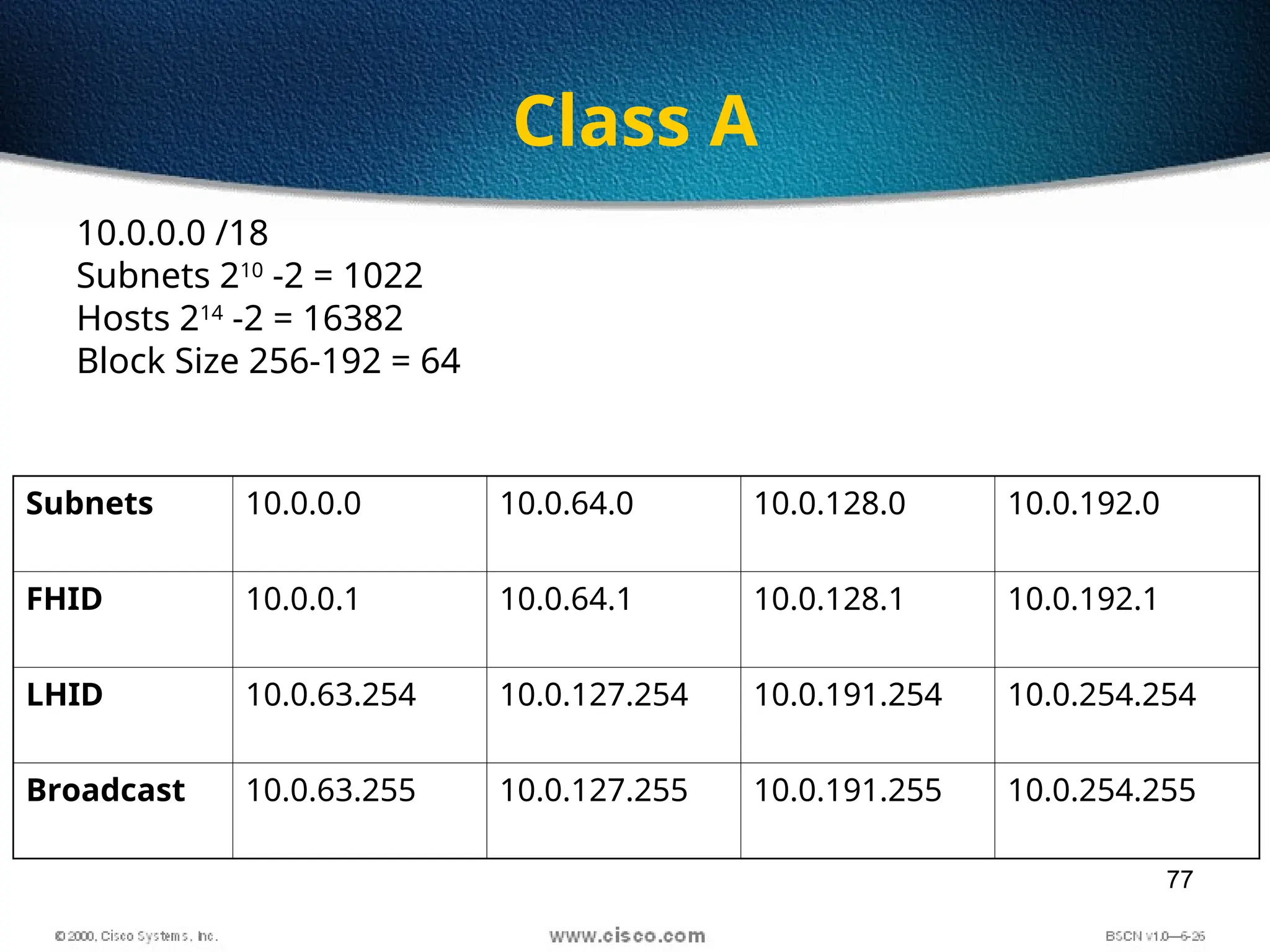
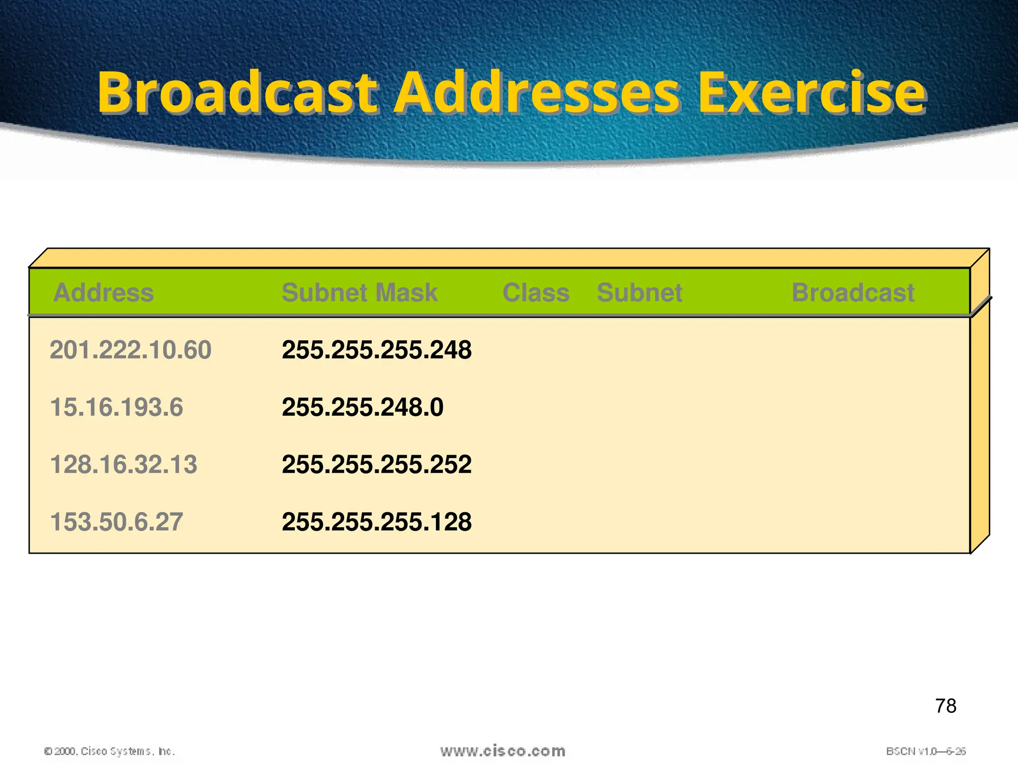
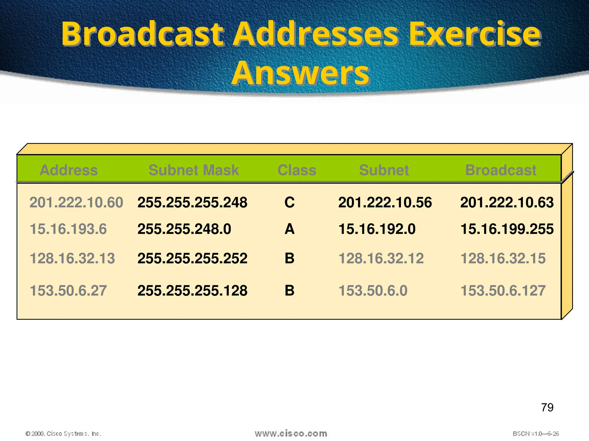
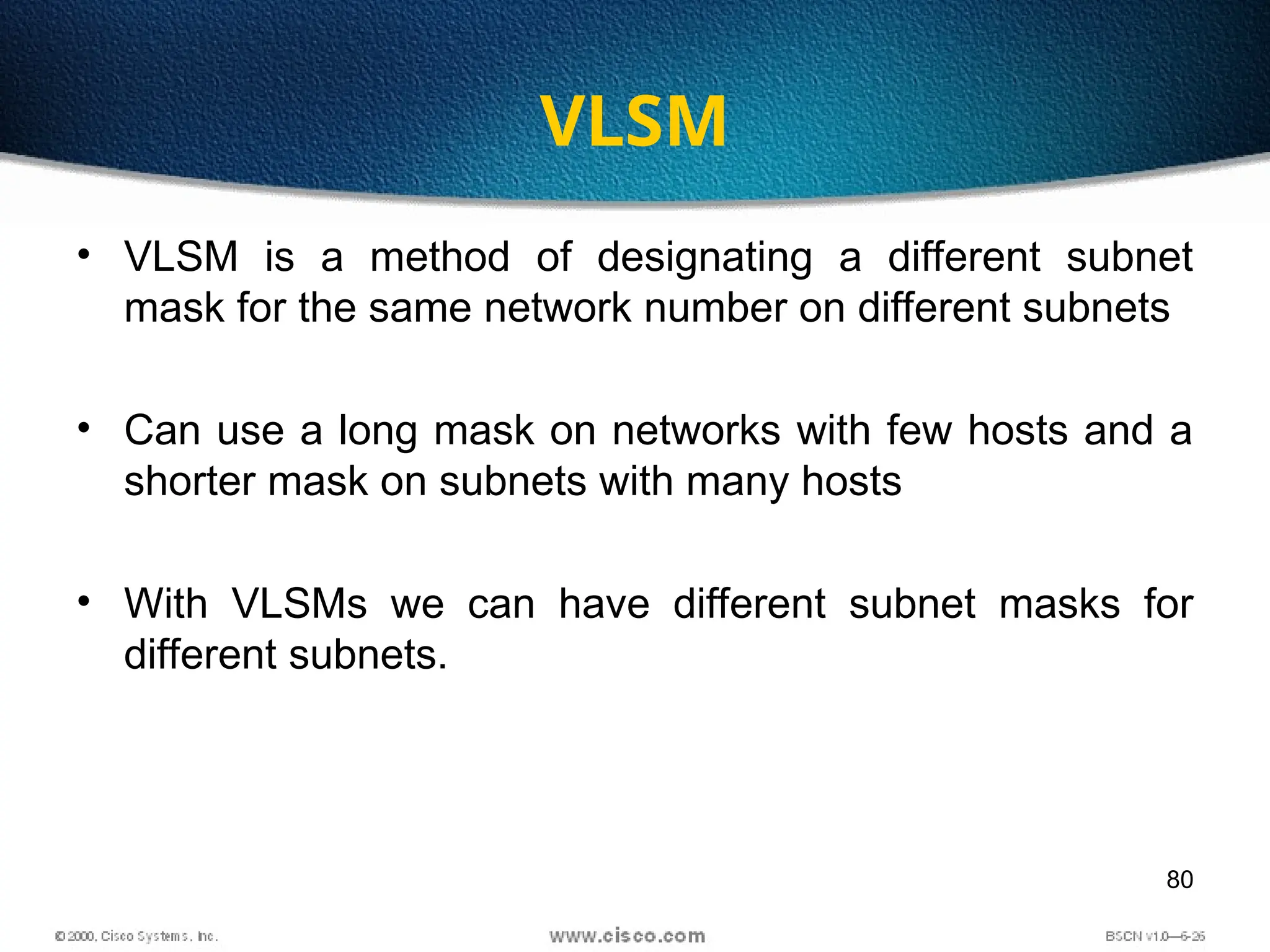
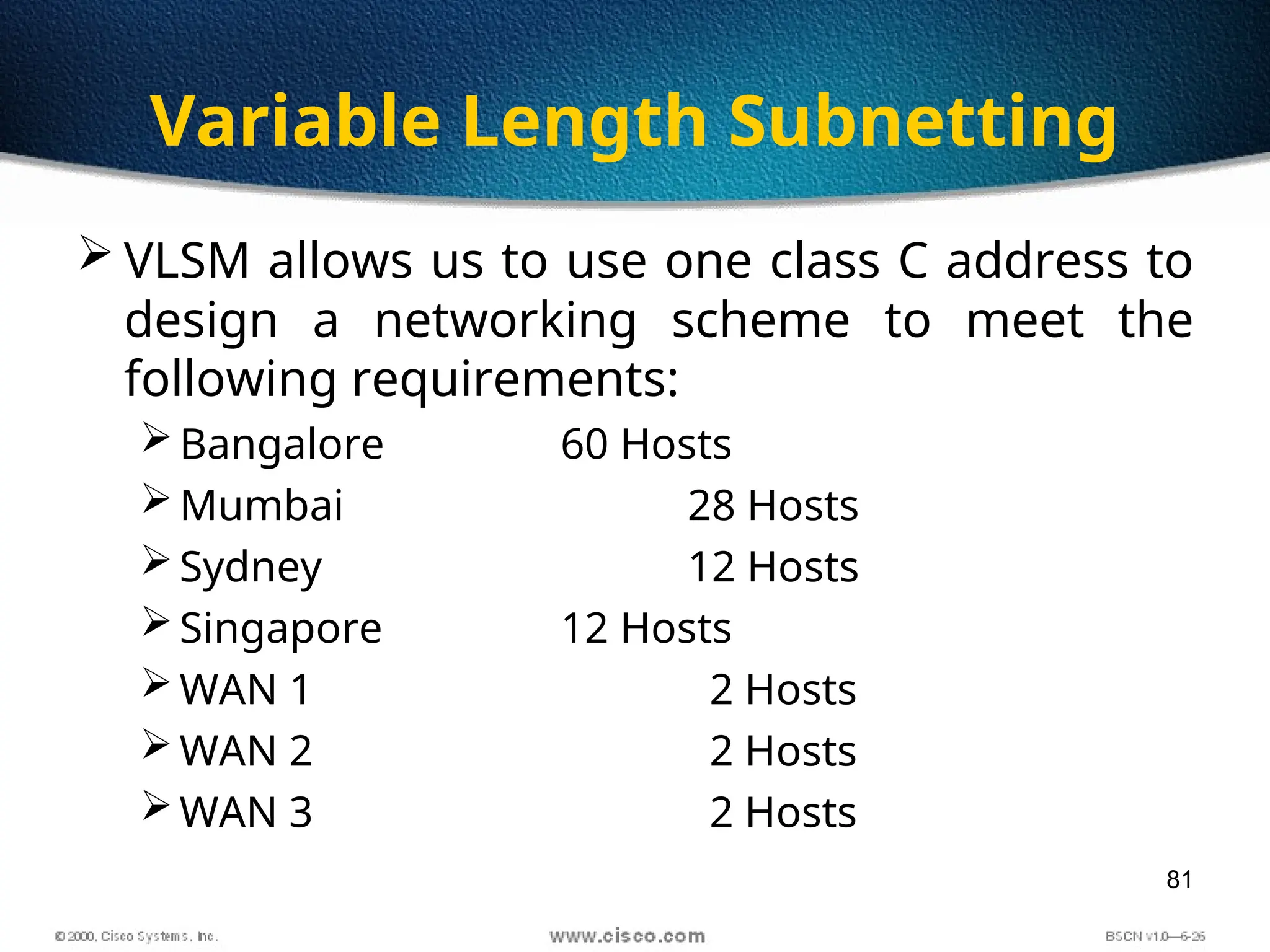
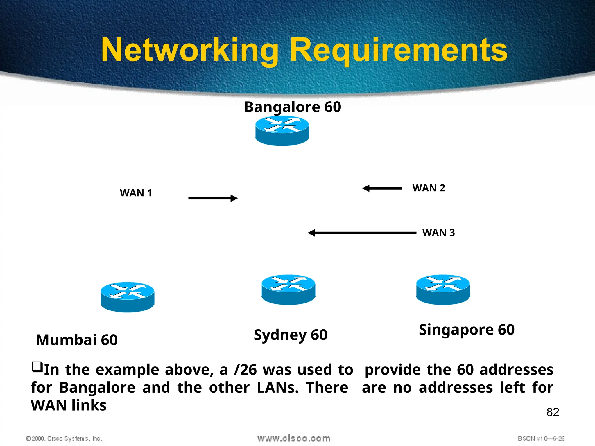
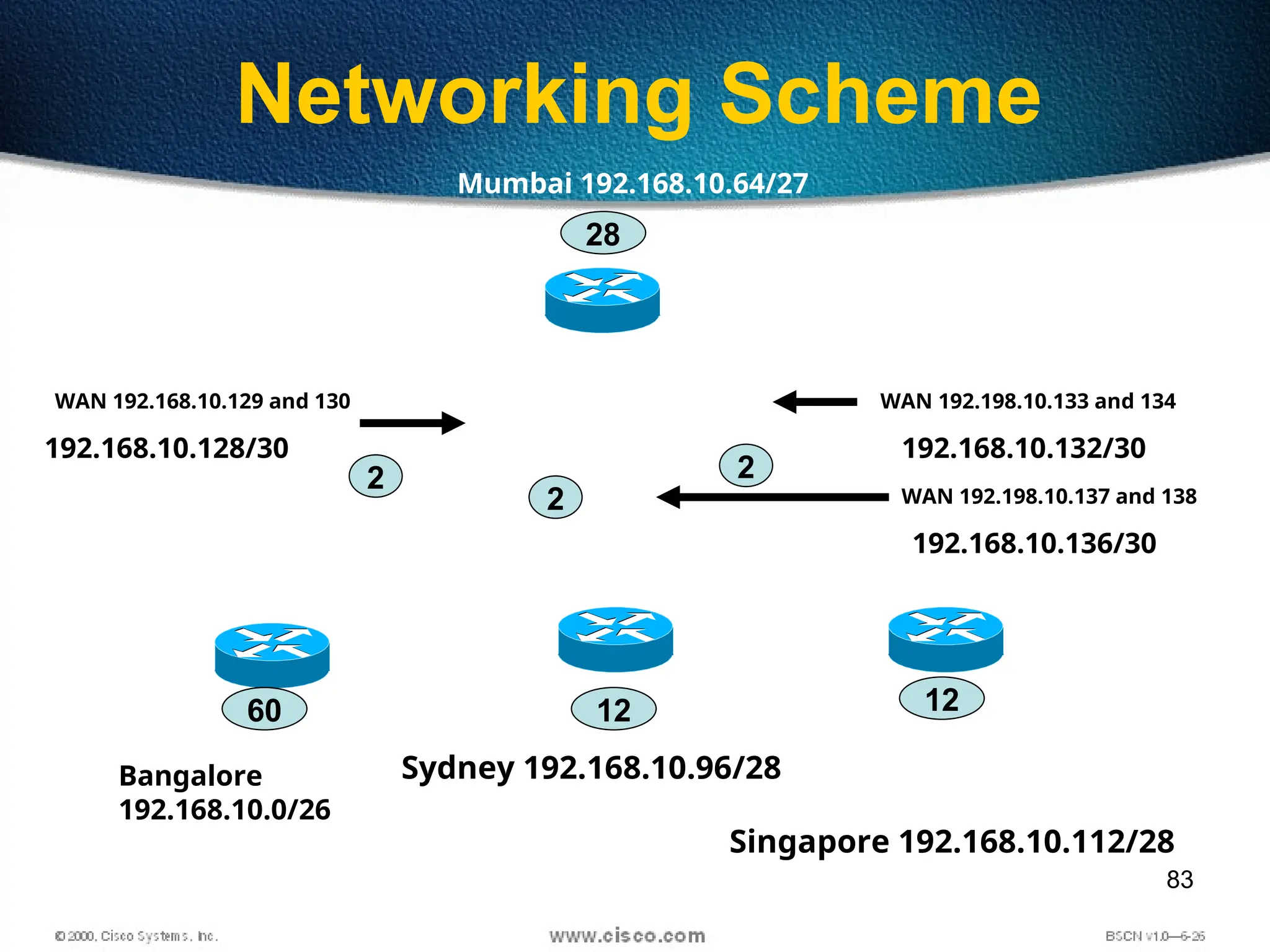
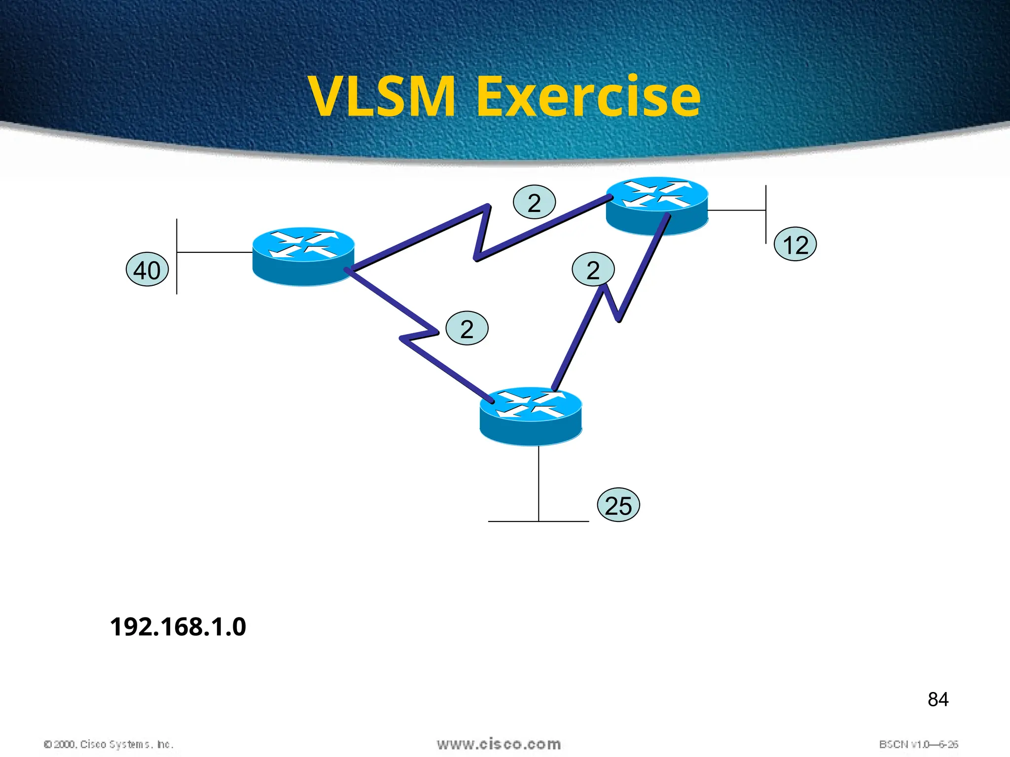
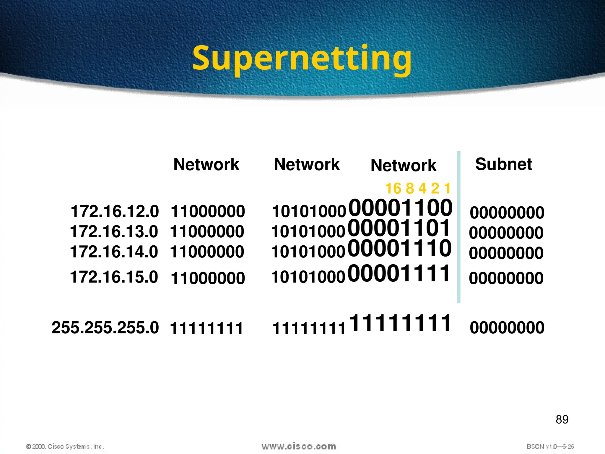
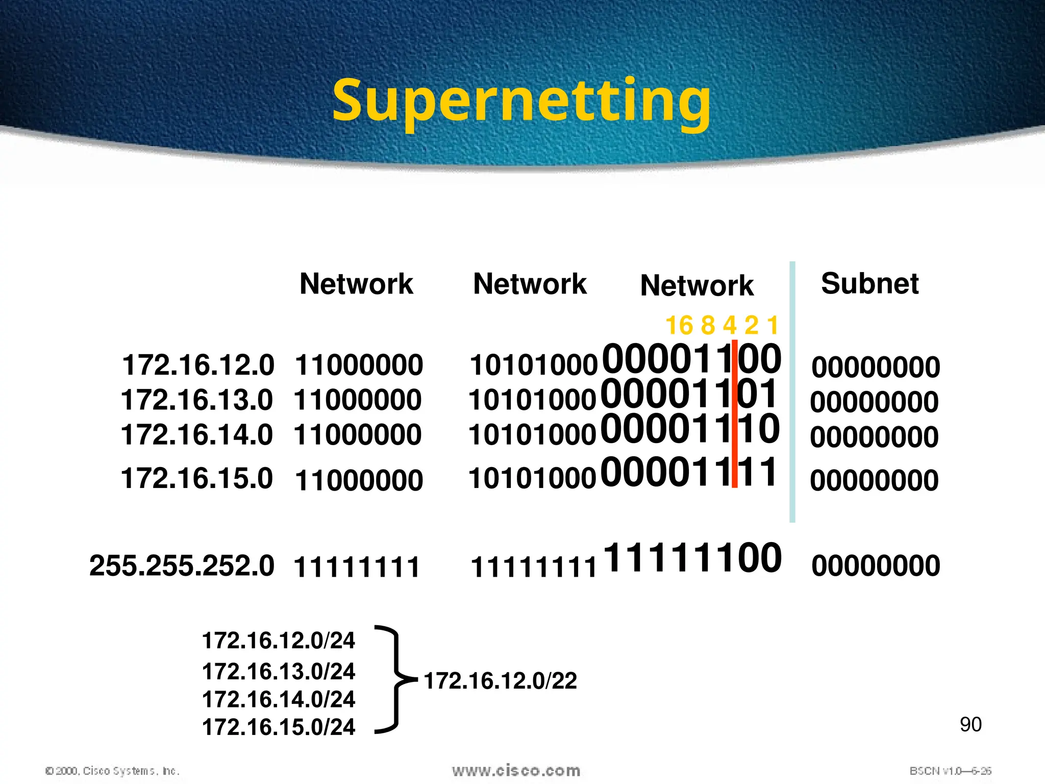
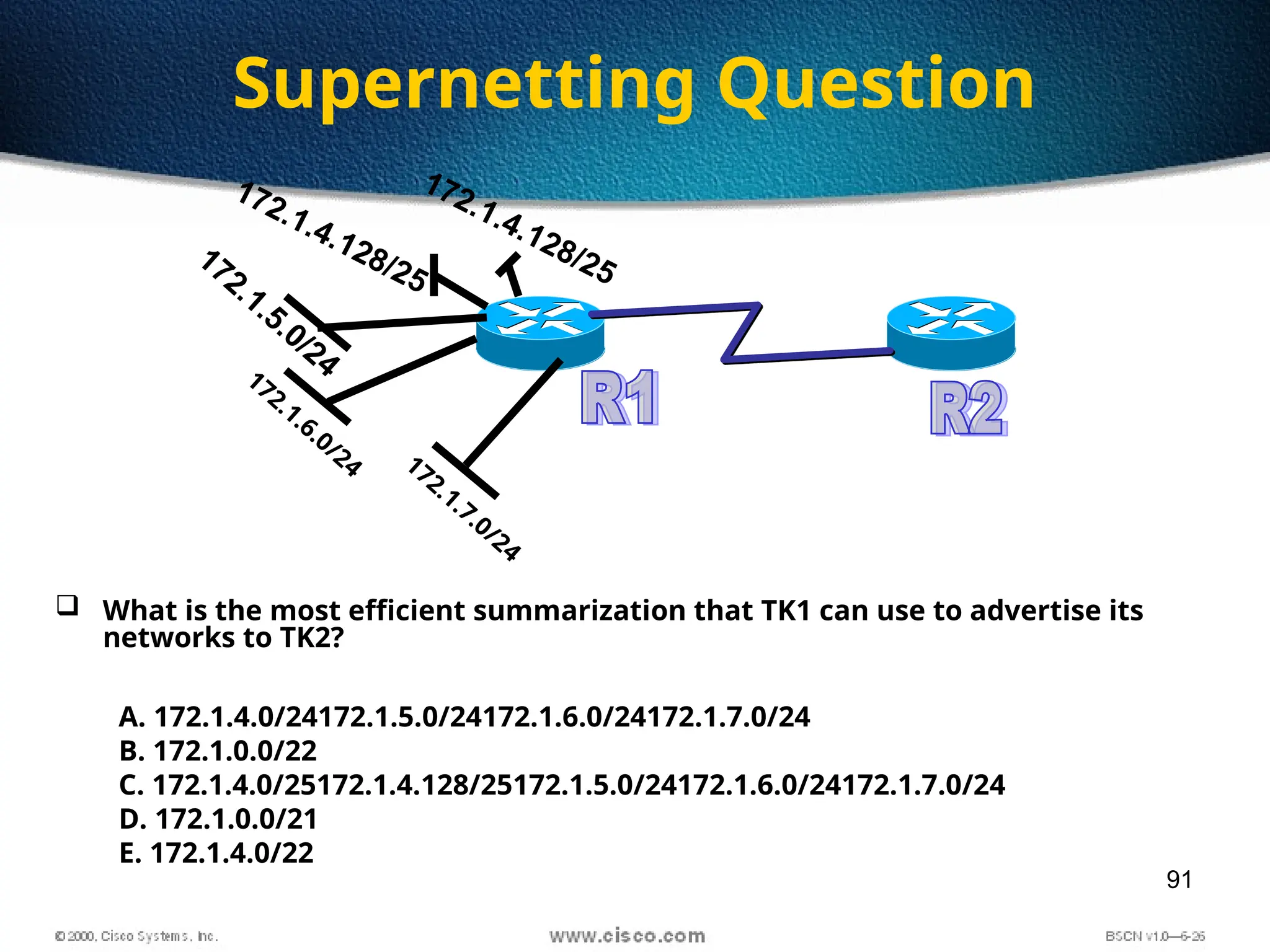
1
2
Found by Xerox Palo Alto Research Center (PARC) in
1975
Original designed as a 2.94 Mbps system to
connect 100 computers on a 1 km cable
Later, Xerox, Intel and DEC drew up a standard
support 10 Mbps – Ethernet II
Basis for the IEEE’s 802.3 specification
Most widely used LAN technology in the world
Origin of Ethernet
3
10 Mbps IEEE Standards - 10BaseT
• 10BaseT  10 Mbps, baseband,
over Twisted-pair cable
• Running Ethernet over twisted-
pair wiring as specified by IEEE
802.3
• Configure in a star pattern
• Twisting the wires reduces EMI
• Fiber Optic has no EMI
Unshielded twisted-pair
RJ-45 Plug and Socket
4
 Unshielded Twisted Pair Cable (UTP)
most popular
maximum length 100 m
prone to noise
Category 1
Category 2
Category 3
Category 4
Category 5
Category 6
Voice transmission of traditional telephone
For data up to 4 Mbps, 4 pairs full-duplex
For data up to 10 Mbps, 4 pairs full-duplex
For data up to 16 Mbps, 4 pairs full-duplex
For data up to 100 Mbps, 4 pairs full-duplex
For data up to 1000 Mbps, 4 pairs full-duplex
Twisted Pair Cables
5
 Baseband Transmission
 Entire channel is used to transmit a single digital signal
 Complete bandwidth of the cable is used by a single signal
 The transmission distance is shorter
 The electrical interference is lower
 Broadband Transmission
 Use analog signaling and a range of frequencies
 Continuous signals flow in the form of waves
 Support multiple analog transmission (channels)
Modem Broadband
Transmission
Network
Card
Baseband
Transmission
Baseband VS Broadband
6
Straight-through cable
7
Straight-through cable pinout
8
Crossover cable
9
Crossover cable
10
Straight-Thru or Crossover
Use straight-through cables for the following cabling:
 Switch to router
 Switch to PC or server
 Hub to PC or server
Use crossover cables for the following cabling:
 Switch to switch
 Switch to hub
 Hub to hub
 Router to router
 PC to PC
 Router to PC
11
12
Decimal to Binary
100
= 1
101
= 10
102
= 100
103
= 1000
1
10
100
1000
172 – Base 10
1
2
4
8
16
32
64
128
10101100– Base 2
20
= 1
21
= 2
22
= 4
23
= 8
24
= 16
25
= 32
26
= 64
27
= 128
10101100
172
2
70
100
172
0
0
4
8
0
32
0
128
172
13
Base 2 Number System
101102 = (1 x 24
= 16) + (0 x 23
= 0) + (1 x 22
= 4) +
(1 x 21
= 2) + (0 x 20
= 0) = 22
14
Converting Decimal to Binary
Convert 20110 to binary:
201 / 2 = 100 remainder 1
100 / 2 = 50 remainder 0
50 / 2 = 25 remainder 0
25 / 2 = 12 remainder 1
12 / 2 = 6 remainder 0
6 / 2 = 3 remainder 0
3 / 2 = 1 remainder 1
1 / 2 = 0 remainder 1
When the quotient is 0, take all the remainders in
reverse order for your answer: 20110 = 110010012
15
Binary to Decimal Chart
16
Hex to Binary to Decimal Chart
17
– Unique addressing allows communication
between end stations.
– Path choice is based on destination address.
• Location is represented by an address
Introduction to TCP/IP
Addresses
172.18.0.2
172.18.0.1
172.17.0.2
172.17.0.1
172.16.0.2
172.16.0.1
SA DA
HDR DATA
10.13.0.0 192.168.1.0
10.13.0.1 192.168.1.1
18
IP Addressing
255 255 255 255
Dotted
Decimal
Maximum
Network Host
128
64
32
16
8
4
2
1
11111111 11111111 11111111 11111111
10101100 00010000 01111010 11001100
Binary
32 Bits
172 16 122 204
Example
Decimal
Example
Binary
1 8 9 16 17 24 25 32
128
64
32
16
8
4
2
1
128
64
32
16
8
4
2
1
128
64
32
16
8
4
2
1
19
•Class A:
•Class B:
•Class C:
•Class D: Multicast
•Class E: Research
IP Address Classes
Network Host Host Host
Network Network Host Host
Network Network Network Host
8 Bits 8 Bits 8 Bits 8 Bits
20
IP Address Classes
1
Class A:
Bits:
0NNNNNNN Host Host Host
8 9 16 17 24 25 32
Range (1-126)
1
Class B:
Bits:
10NNNNNN Network Host Host
8 9 16 17 24 25 32
Range (128-191)
1
Class C:
Bits:
110NNNNN Network Network Host
8 9 16 17 24 25 32
Range (192-223)
1
Class D:
Bits:
1110MMMM Multicast Group Multicast Group Multicast Group
8 9 16 17 2425 32
Range (224-239)
21
Host Addresses
172.16.2.2
172.16.3.10
172.16.12.12
10.1.1.1
10.250.8.11
10.180.30.118
E1
172.16 12 12
Network Host
. . Network Interface
172.16.0.0
10.0.0.0
E0
E1
Routing Table
172.16.2.1
10.6.24.2
E0
22
Classless Inter-Domain Routing
(CIDR)
• Basically the method that ISPs (Internet
Service Providers) use to allocate an amount
of addresses to a company, a home
• Ex : 192.168.10.32/28
• The slash notation (/) means how many bits
are turned on (1s)
23
CIDR Values
24
11111111
Determining Available Host
Addresses
172 16 0 0
10101100 00010000 00000000 00000000
16
15
14
13
12
11
10
9
8
7
6
5
4
3
2
1
Network Host
00000000 00000001
11111111 11111111
11111111 11111110
...
...
00000000 00000011
11111101
1
2
3
65534
65535
65536
–
...
2
65534
N
2N
– 2 = 216
– 2 = 65534
25
IP Address Classes Exercise
Address Class Network Host
10.2.1.1
128.63.2.100
201.222.5.64
192.6.141.2
130.113.64.16
256.241.201.10
26
IP Address Classes Exercise
Answers
Address Class Network Host
10.2.1.1
128.63.2.100
201.222.5.64
192.6.141.2
130.113.64.16
256.241.201.10
A
B
C
C
B
Nonexistent
10.0.0.0
128.63.0.0
201.222.5.0
192.6.141.0
130.113.0.0
0.2.1.1
0.0.2.100
0.0.0.64
0.0.0.2
0.0.64.16
27
Subnetting
Subnetting is logically dividing the
network by extending the 1’s used in
SNM
Advantage
Can divide network in smaller parts
Restrict Broadcast traffic
Security
Simplified Administration
28
Formula
 Number of subnets – 2x
-2
Where X = number of bits borrowed
 Number of Hosts – 2y
-2
Where y = number of 0’s
 Block Size = Total number of Address
Block Size = 256-Mask
29
Subnetting
 Classful IP Addressing SNM are a set of 255’s and 0’s.
 In Binary it’s contiguous 1’s and 0’s.
 SNM cannot be any value as it won’t follow the rule of
contiguous 1’s and 0’s.
 Possible subnet mask values
– 0
– 128
– 192
– 224
– 240
– 248
– 252
– 254
– 255
30
• Network 172.16.0.0
172.16.0.0
Addressing Without Subnets
172.16.0.1 172.16.0.2 172.16.0.3
…...
172.16.255.253 172.16.255.254
31
• Network 172.16.0.0
Addressing with Subnets
172.16.1.0 172.16.2.0
172.16.3.0
172.16.4.0
32
Subnet Addressing
172.16.2.200
172.16.2.2
172.16.2.160
172.16.2.1
172.16.3.5
172.16.3.100
172.16.3.150
E0
172.16
Network
Network Interface
172.16.0.0
172.16.0.0
E0
E1
New Routing Table
2 160
Host
. .
172.16.3.1
E1
33
Subnet Addressing
172.16.2.200
172.16.2.2
172.16.2.160
172.16.2.1
172.16.3.5
172.16.3.100
172.16.3.150
172.16.3.1
E0
E1
172.16 2 160
Network Host
. . Network Interface
172.16.2.0
172.16.3.0
E0
E1
New Routing Table
Subnet
34
Subnet Mask
172 16 0 0
255 255 0 0
255 255 255 0
IP
Address
Default
Subnet
Mask
8-Bit
Subnet
Mask
Network Host
Network Host
Network Subnet Host
• Also written as “/16,” where 16 represents the number of 1s
in the mask
• Also written as “/24,” where 24 represents the number of
1s in the mask
11111111 11111111 00000000 00000000
35
Decimal Equivalents of Bit
Patterns
0 0 0 0 0 0 0 0 = 0
1 0 0 0 0 0 0 0 = 128
1 1 0 0 0 0 0 0 = 192
1 1 1 0 0 0 0 0 = 224
1 1 1 1 0 0 0 0 = 240
1 1 1 1 1 0 0 0 = 248
1 1 1 1 1 1 0 0 = 252
1 1 1 1 1 1 1 0 = 254
1 1 1 1 1 1 1 1 = 255
128 64 32 16 8 4 2 1
36
16
Network Host
172 0 0
10101100
11111111
10101100
00010000
11111111
00010000
00000000
00000000
10100000
00000000
00000000
•Subnets not in use—the default
00000010
Subnet Mask Without Subnets
172.16.2.160
255.255.0.0
Network
Number
37
•Network number extended by eight bits
Subnet Mask with Subnets
16
Network Host
172.16.2.160
255.255.255.0
172 2 0
10101100
11111111
10101100
00010000
11111111
00010000
11111111
00000010
10100000
00000000
00000000
00000010
Subnet
Network
Number
128
192
224
240
248
252
254
255
38
Subnet Mask with Subnets
(cont.)
Network Host
172.16.2.160
255.255.255.192
10101100
11111111
10101100
00010000
11111111
00010000
11111111
00000010
10100000
11000000
10000000
00000010
Subnet
•Network number extended by ten bits
16
172 2 128
Network
Number
128
192
224
240
248
252
254
255
128
192
224
240
248
252
254
255
39
Subnet Mask Exercise
Address Subnet Mask Class Subnet
172.16.2.10
10.6.24.20
10.30.36.12
255.255.255.0
255.255.240.0
255.255.255.0
40
Subnet Mask Exercise Answers
Address Subnet Mask Class Subnet
172.16.2.10
10.6.24.20
10.30.36.12
255.255.255.0
255.255.240.0
255.255.255.0
B
A
A
172.16.2.0
10.6.16.0
10.30.36.0
41
Broadcast Addresses
172.16.1.0
172.16.2.0
172.16.3.0
172.16.4.0
172.16.3.255
(Directed Broadcast)
255.255.255.255
(Local Network Broadcast)
X
X
172.16.255.255
(All Subnets Broadcast)
42
Addressing Summary Example
10101100
11111111
10101100
00010000
11111111
00010000
11111111
00000010
10100000
11000000
10000000
00000010
10101100 00010000 00000010 10111111
10101100 00010000 00000010 10000001
10101100 00010000 00000010 10111110
Host
Mask
Subnet
Broadcast
Last
First
172.16.2.160
255.255.255.192
172.16.2.128
172.16.2.191
172.16.2.129
172.16.2.190
1
2
3
4
5
6
7
8
9
16
172 2 160
43
IP Host Address: 172.16.2.121
Subnet Mask: 255.255.255.0
• Subnet Address = 172.16.2.0
• Host Addresses = 172.16.2.1–172.16.2.254
• Broadcast Address = 172.16.2.255
• Eight Bits of Subnetting
Network Subnet Host
10101100 00010000 00000010 11111111
172.16.2.121:
255.255.255.0:
10101100
11111111
Subnet: 10101100 00010000
00010000
11111111
00000010
00000010
11111111
01111001
00000000
00000000
Class B Subnet Example
Broadcast:
Network
44
Subnet Planning
Other
Subnets
192.168.5.16
192.168.5.32 192.168.5.48
20 Subnets
5 Hosts per Subnet
Class C Address:
192.168.5.0
45
11111000
IP Host Address: 192.168.5.121
Subnet Mask: 255.255.255.248
Network Subnet Host
192.168.5.121: 11000000
11111111
Subnet: 11000000 10101000
10101000
11111111
00000101
00000101
11111111
01111001
01111000
255.255.255.248:
Class C Subnet Planning
Example
• Subnet Address = 192.168.5.120
• Host Addresses = 192.168.5.121–192.168.5.126
• Broadcast Address = 192.168.5.127
• Five Bits of Subnetting
Broadcast:
Network
Network
11000000 10101000 00000101 01111111
46
Exercise
• 192.168.10.0
• /27
? – SNM
? – Block Size
?- Subnets
47
Exercise
• /27
? – SNM – 224
? – Block Size = 256-224 = 32
?- Subnets
Subnets 10.0 10.32 10.64
FHID 10.1 10.33
LHID 10.30 10.62
Broadcast 10.31 10.63
48
Exercise
• 192.168.10.0
• /30
? – SNM
? – Block Size
?- Subnets
49
Exercise
• /30
? – SNM – 252
? – Block Size = 256-252 = 4
?- Subnets
Subnets 10.0 10.4 10.8
FHID 10.1 10.5
LHID 10.2 10.6
Broadcast 10.3 10.7
50
Exercise
Mask Subnets Host
/26 ? ? ?
/27 ? ? ?
/28 ? ? ?
/29 ? ? ?
/30 ? ? ?
51
Exercise
Mask Subnets Host
/26 192 4 62
/27 224 8 30
/28 240 16 14
/29 248 32 6
/30 252 64 2
52
Exam Question
• Find Subnet and Broadcast address
– 192.168.0.100/27
53
Exercise
192.168.10.54 /29
Mask ?
Subnet ?
Broadcast ?
54
Exercise
192.168.10.130 /28
Mask ?
Subnet ?
Broadcast ?
55
Exercise
192.168.10.193 /30
Mask ?
Subnet ?
Broadcast ?
56
Exercise
192.168.1.100 /26
Mask ?
Subnet ?
Broadcast ?
57
Exercise
192.168.20.158 /27
Mask ?
Subnet ?
Broadcast ?
58
Class B
172.16.0.0 /19
Subnets ?
Hosts ?
Block Size ?
59
Class B
172.16.0.0 /19
Subnets 23
-2 = 6
Hosts 213
-2 = 8190
Block Size 256-224 = 32
Subnets 0.0 32.0 64.0 96.0
FHID 0.1 32.1 64.1 96.1
LHID 31.254 63.254 95.254 127.254
Broadcast 31.255 63.255 95.255 127.255
60
Class B
172.16.0.0 /27
Subnets ?
Hosts ?
Block Size ?
61
Class B
172.16.0.0 /27
Subnets 211
-2 = 2046
Hosts 25
-2 = 30
Block Size 256-224 = 32
Subnets 0.0 0.32 0.64 0.96
FHID 0.1 0.33 0.65 0.97
LHID 0.30 0.62 0.94 0.126
Broadcast 0.31 0.63 0.95 0.127
62
Class B
172.16.0.0 /23
Subnets ?
Hosts ?
Block Size ?
63
Class B
172.16.0.0 /23
Subnets 27
-2 = 126
Hosts 29
-2 = 510
Block Size 256-254 = 2
Subnets 0.0 2.0 4.0 6.0
FHID 0.1 2.1 4.1 6.1
LHID 1.254 3.254 5.254 7.254
Broadcast 1.255 3.255 5.255 7.255
64
Class B
172.16.0.0 /24
Subnets ?
Hosts ?
Block Size ?
65
Class B
172.16.0.0 /24
Subnets 28
-2 = 254
Hosts 28
-2 = 254
Block Size 256-255 = 1
Subnets 0.0 1.0 2.0 3.0
FHID 0.1 1.1 2.1 3.1
LHID 0.254 1.254 2.254 3.254
Broadcast 0.255 1.255 2.255 3.255
66
Class B
172.16.0.0 /25
Subnets ?
Hosts ?
Block Size ?
67
Class B
172.16.0.0 /25
Subnets 29
-2 = 510
Hosts 27
-2 = 126
Block Size 256-128 = 128
Subnets 0.0 0.128 1.0 1.128 2.0 2.128
FHID 0.1 0.129 1.1 1.129 2.1 2.129
LHID 0.126 0.254 1.126 1.254 2.126 2.254
Broadcast 0.127 0.255 1.127 1.255 2.127 2.255
69
Find out Subnet and Broadcast
Address
• 172.16.85.30/29
70
Find out Subnet and Broadcast
Address
• 172.30.101.62/23
71
Find out Subnet and Broadcast
Address
• 172.20.210.80/24
72
Exercise
• Find out the mask which gives 100
subnets for class B
73
Exercise
• Find out the Mask which gives 100 hosts
for Class B
74
Class A
10.0.0.0 /10
Subnets ?
Hosts ?
Block Size ?
75
Class A
10.0.0.0 /10
Subnets 22
-2 = 2
Hosts 222
-2 = 4194302
Block Size 256-192 = 64
Subnets 10.0 10.64 10.128 10.192
FHID 10.0.0.1 10.64.0.1 10.128.0.1 10.192.0.1
LHID 10.63.255.254 10.127.255.254 10.191.255.254 10.254.255.254
Broadcast 10.63.255.255 10.127.255.255 10.191.255.255 10.254.255.255
76
Class A
10.0.0.0 /18
Subnets ?
Hosts ?
Block Size ?
77
Class A
10.0.0.0 /18
Subnets 210
-2 = 1022
Hosts 214
-2 = 16382
Block Size 256-192 = 64
Subnets 10.0.0.0 10.0.64.0 10.0.128.0 10.0.192.0
FHID 10.0.0.1 10.0.64.1 10.0.128.1 10.0.192.1
LHID 10.0.63.254 10.0.127.254 10.0.191.254 10.0.254.254
Broadcast 10.0.63.255 10.0.127.255 10.0.191.255 10.0.254.255
78
Broadcast Addresses Exercise
Address Class Subnet Broadcast
201.222.10.60 255.255.255.248
Subnet Mask
15.16.193.6 255.255.248.0
128.16.32.13 255.255.255.252
153.50.6.27 255.255.255.128
79
Broadcast Addresses Exercise
Answers
153.50.6.127
Address Class Subnet Broadcast
201.222.10.60 255.255.255.248 C 201.222.10.63
201.222.10.56
Subnet Mask
15.16.193.6 255.255.248.0 A 15.16.199.255
15.16.192.0
128.16.32.13 255.255.255.252 B 128.16.32.15
128.16.32.12
153.50.6.27 255.255.255.128 B 153.50.6.0
80
VLSM
• VLSM is a method of designating a different subnet
mask for the same network number on different subnets
• Can use a long mask on networks with few hosts and a
shorter mask on subnets with many hosts
• With VLSMs we can have different subnet masks for
different subnets.
81
Variable Length Subnetting
 VLSM allows us to use one class C address to
design a networking scheme to meet the
following requirements:
Bangalore 60 Hosts
Mumbai 28 Hosts
Sydney 12 Hosts
Singapore 12 Hosts
WAN 1 2 Hosts
WAN 2 2 Hosts
WAN 3 2 Hosts
82
Networking Requirements
Bangalore 60
Mumbai 60 Sydney 60 Singapore 60
WAN 1
WAN 2
WAN 3
In the example above, a /26 was used to provide the 60 addresses
for Bangalore and the other LANs. There are no addresses left for
WAN links
83
Networking Scheme
Mumbai 192.168.10.64/27
Bangalore
192.168.10.0/26
Sydney 192.168.10.96/28
Singapore 192.168.10.112/28
WAN 192.168.10.129 and 130 WAN 192.198.10.133 and 134
WAN 192.198.10.137 and 138
60 12 12
28
2
2
2
192.168.10.128/30
192.168.10.136/30
192.168.10.132/30
84
VLSM Exercise
2
2
2
40
25
12
192.168.1.0
85
VLSM Exercise
2 2
2
40
25
12
192.168.1.0
192.168.1.4/30
192.168.1.8/30
192.168.1.12/30
192.168.1.16/28
192.168.1.32/27
192.168.1.64/26
86
VLSM Exercise
2
2
8
15
5
192.168.1.0
2
2
35
87
Summarization
• Summarization, also called route aggregation, allows
routing protocols to advertise many networks as one
address.
• The purpose of this is to reduce the size of routing
tables on routers to save memory
• Route summarization (also called route aggregation
or supernetting) can reduce the number of routes
that a router must maintain
• Route summarization is possible only when a proper
addressing plan is in place
• Route summarization is most effective within a
subnetted environment when the network addresses
are in contiguous blocks
88
Summarization
89
Supernetting
Network Subnet
172.16.12.0 11000000
11111111
10101000
11111111
00001100
11111111
255.255.255.0
Network
Network
00000000
00000000
16 8 4 2 1
172.16.13.0 11000000 1010100000001101 00000000
172.16.14.0 11000000 1010100000001110 00000000
172.16.15.0 11000000 1010100000001111 00000000
90
Supernetting
Network Subnet
172.16.12.0 11000000
11111111
10101000
11111111
00001100
11111100
255.255.252.0
Network
Network
00000000
00000000
16 8 4 2 1
172.16.13.0 11000000 1010100000001101 00000000
172.16.14.0 11000000 1010100000001110 00000000
172.16.15.0 11000000 1010100000001111 00000000
172.16.12.0/24
172.16.13.0/24
172.16.14.0/24
172.16.15.0/24
172.16.12.0/22
91
Supernetting Question
172.1.7.0/24
172.1.6.0/24
172.1.5.0/24
172.1.4.128/25
172.1.4.128/25
 What is the most efficient summarization that TK1 can use to advertise its
networks to TK2?
A. 172.1.4.0/24172.1.5.0/24172.1.6.0/24172.1.7.0/24
B. 172.1.0.0/22
C. 172.1.4.0/25172.1.4.128/25172.1.5.0/24172.1.6.0/24172.1.7.0/24
D. 172.1.0.0/21
E. 172.1.4.0/22

Networking Media Origin of internet (Alur Transfer Data)

Editor's Notes

  • #3 TK-23-24
  • #17 Purpose: This is an introduction slide to the IP addressing section. Emphasize: Stations with internetwork access must have unique addresses.
  • #18 Layer 3 of 3 Emphasize: In layer 3, an example of dotted decimal format and binary are displayed. IP address format is dotted decimal. Dotted decimal makes it easy to work with IP addresses. However, in this course we will work with the addresses on the bit level, so we will convert these addresses into binary, make changes to them, and convert them back. The central authority for addresses is the Internet Assigned Numbers Authority (IANA). Note: This most common form of addressing reflects the widely used IP version 4. Faced with the problem of depleting available addresses, Internet Engineering Task Force (IETF) work is under way for a backward-compatible next generation of IP (IPng, also called IP 6). IP 6 will offer expanded routing and addressing capabilities with 128-bit addresses rather than the 32-bit addressing shown on the graphic. Addresses from both IP versions will coexist. Initial occurrences will probably be at locations with address translator software and firewalls.
  • #19 Slide 1 of 2 Purpose: This graphic describes the three most common classes of IP address. Emphasize: Discuss classes of addresses. Each address contains information about the network number and the host number of the device. Class A addresses are for very large organizations, Class B addresses are for smaller organizations, and Class C addresses for even smaller ones. As the number of networks grows, classes may eventually be replaced by another addressing mechanism, such as classless interdomain routing (CIDR). RFC 1467, Status of CIDR Deployment in the Internet, presents information about CIDR. RFC 1817, CIDR and Classful Routing, also presents CIDR information.
  • #20 Slide 2 of 2 Emphasize: Highlight the fixed values that start each class address. The first octet rule states that when an address falls into a specified range, it belongs to a certain class. Students should soon be able to recognize the address class of any IP address on sight. Note: If time or interest permits, you can use the initial bit patterns in the first octet and show how a class of IP network derives the range of network numbers for that IP address class.
  • #21 Purpose: This figure presents an overview of host and network address conventions. Emphasize: In the example, 172.16.0.0 and 10.0.0.0 refer to the wires at each end of the router. Explain how the routing table is used. Entries in the routing table refer to the network only. The router does not know the location of hosts; it knows the location of networks. .
  • #24 Purpose: This figure explains how to calculate the number of available hosts in a network. Emphasize: 2N-2 is the calculation to determine available hosts. N is the number of binary digits in the host field. Subtract 2 because a host cannot be all 0s or 1s. The same principle applies when determining the number of available networks.
  • #25 Layer 1 of 2 Purpose: This exercise verifies that the students understand IP address classes, network numbers, and host numbers. Give the students time to list the address class, network, and host number for each IP address in the table. Review the correct answers interactively. The answers are given in the following figure.
  • #26 Layer 2 of 2 Purpose: The answers to the exercise are given in the figure. Note: Students can also find the answers to this exercise in the Appendix D, “Answers.”
  • #29 Advantages of Subnetting Subnetting is often used to accommodate a divided physical topology or to restrict broadcast traffic on a network.Other advantages of subnetting include improved secu ­ rity (by restricting unauthorized traffic behind routers)and simplified administration (by delegating control of subnets to other departments or administrators). Accommodating Physical Topology Suppose you are designing a campus network with 200 hosts spread over four buildings —Voter Hall,Twilight Hall,Monroe Hall, and Sunderland Hall.You want each of these four buildings to include 50 hosts.If your ISP has allocated to you the Class C network 208.147.66.0,you can use the addresses 208.147.66.1 –208.147.66.254 for your 200 hosts. Restricting Broadcast Traffic A broadcast is a network message sent from a single computer and distributed to all other devices on the same physical network segment. Broadcasts are resource-intensive because they use up network bandwidth and request the attention of every network adapter and processor on the local network segment. Routers block broadcasts and protect networks from becoming overburdened with unnecessary traffic.Because routers also define the logical limits of subnets,subnet ­ ting a network indirectly allows you to limit the propagation of broadcast traffic in that network.
  • #30 Purpose: This figure explains what networks look like without subnets. Emphasize: Without subnets, use of network addressing space is inefficient. The Class B network is like a highway with no exits—there is no place to exit, so all of the traffic is in one line.
  • #31 Purpose: This figure describes network structure when subnets are used. Emphasize: The host bits of an IP address can be subdivided into a subnetwork section and a host section. The subnetwork section in this example is the full third octet. Point out the difference in the addressing between the previous slide and this slide. A subnetted address space is like a highway with exits. A network device uses a subnet mask to determine what part of the IP address is used for the network, the subnet, and the device ID. A subnet mask is a 32-bit value containing a number of one bits for the network and subnet ID, and a number of zero bits for the host ID. Given its own IP address and subnet mask, a device can determine if an IP packet is destined for 1) a device on its own subnet, 2) a device on a different subnet on its own network, or 3) a device on a different network. A device can determine what class of address the device has been assigned from its own IP address. The subnet mask then tells the device where the boundary is between the subnet ID and the host ID.
  • #32 Layer 1 of 2 Purpose: This figure shows what would happen if there were no subnetting. Emphasize: If networks could not be broken down into more granular subnetworks, few networks could exist, each with a capacity for many hosts.
  • #33 Layer 1 of 2 Emphasize: By turning on more bits in the mask, we reserve some bits as network information and can use these bits to describe subnetworks. Describe how the router makes use of this technique. Point out that there is more information in the routing table now. Note: As you enter the discussion about subnet masks, a question might arise about whether it is legal to define a discontiguous subnet mask. A discontiguous subnet mask consists of intervening zeros, as in 101111011000, rather than all ones followed by zeros, as in 1111111100000000. The question has two answers. According to RFC 950 that describes IP, a discontiguous subnet mask is legal. However, the hardware expense to produce an interface that supports discontiguous masking is cost prohibitive. Thus in practice it is not supported on most vendors’ equipment, including Cisco. Also, discontiguous masking has no benefit, and it is much more difficult to maintain a network based on this design. Later RFCs make noncontiguous subnet masks illegal because they are incompatible with future addressing schemes such as CIDR.
  • #34 Emphasize: Turn on more bits to represent subnets. Compare the default or standard subnet mask with the subnet mask in the slide. The following are the rules for IP addressing: An address is 32 bits, divided into three components: First octet rule bits Network bits (path selection bits) Node bits The first octet rule states that the most significant bit pattern in the first octet determines the class of the address. Path selection bits cannot be all ones or zeros. Certain addresses are reserved. RFC 1918 defines some of those. Prefix or mask one bits are path selection significant; zero bits are host bits and therefore not significant. Use the logical AND to combine the address and mask bits to get the subnet address. The maximum number of available subnets equals 2 prefix bits - 2; the maximum number of available hosts equals 2 32- prefix bits - 2.
  • #35 Purpose: This figure explains how subnet masks are converted to decimal addresses. Emphasize: Review binary-to-decimal conversion, bit weighting, and conversion. Explain the logical AND. One possible explanation of the logical AND follows. We will need to be able to perform a logical AND on the binary numbers. Just take two binary numbers and place one above the other. The ones in the bottom are like a pipe—the number above it just drops through. The zeros are like a clogged pipe, so nothing comes out in the answer. Presenting a truth table will help some students understand. You might need to give more than one explanation. Note: You might want to hand out a binary-to-decimal conversion sheet if you have not already done so. We have not included one in the lab section. It is more useful to have one that is on a separate page from the labs.
  • #36 Purpose: This graphic explains how routers use addresses that have no subnet mask. Emphasize: Explain how masking works at the bit level. Zero bits mask host information. Note: This is an easy place to lose students. At this point, they need to learn several abstract mathematical concepts before we can show them how to lay out an IP-addressed network. To the novice, these techniques may seem unrelated, making the presentation confusing. To a more experienced audience, these techniques will be familiar.
  • #37 Slide 1 of 2 Purpose: This figure shows how the router determines an address when subnetting is used. Emphasize: This example makes a Class B address space look like a collection of Class C address spaces. Now the logical AND allows us to extract the subnet number as well as the assigned network number. An exercise follows that tests the students’ understanding of subnet masks.
  • #38 Slide 2 of 2 Purpose: This figure shows how the router determines an address when subnetting is used. Emphasize: This example is different from the previous example in that the the subnet and host are divided within an octet. Transition: An exercise follows that tests the students’ understanding of subnet masks.
  • #39 Layer 1 of 2 Purpose: This exercise is for the students to take the given IP addresses and associated subnet masks and perform a logical AND to extract the subnet number. Provide time in class and review the answers after most of the students have finished. The answers are given in the following figure.
  • #40 Layer 2 of 2 Purpose: The answers to the exercise are given in the figure. Note: Students can also find the answers to this exercise in the Appendix D, “Answers.”
  • #41 Purpose: This figure explains how broadcast addresses work. Emphasize: A range of addresses is needed to allocate address space. A valid range of addresses is between subnet zero and the directed broadcast. The following RFCs provide more information about broadcasts: RFC 919, Broadcasting Internet Datagrams RFC 922, Broadcasting IP Datagrams in the Presence of Subnets Cisco’s support for broadcasts generally complies with these two RFCs. It does not support multisubnet broadcasts that are defined in RFC 922.
  • #42 Layer 9 of 9 Emphasize: In layer 9, convert binary back to dotted decimal.
  • #43 Purpose: This figure shows an example of a Class B network with a subnet.
  • #44 Purpose: This figure explains how to plan subnet numbers. Emphasize: What if this were a Class B address? How many bits would we have for subnetting then? Where do you want to draw the line now? Alternatives to review: Creating the subnet at the octet boundary is easier to work with—more host bits and more subnet bits. Explain that the decision is really a guess on how you think your network will grow—will it have more subnets or more hosts? RFC 1219: Mirroring hedges the subnetting decision by buying time. Do not use mirroring if you intend to use route summarization or variable-length subnet masking (VLSM); they are incompatible with mirroring.
  • #45 Purpose: This figure shows an example of a Class C network with a subnet. Emphasize: Contrast the Class C network subnet mask with the previous Class B example.
  • #52 Bs = 32 Subnet 192.168.0.96 B/c – 192.168.0.127
  • #53 Mask = 248 BS = 8 Nw= 48 B/c - 55
  • #54 Mask = 240 BS=16 NW-128 B/c-143
  • #55 Mask = 252 BS=4 NW-192 B/c-195
  • #56 Mask = 192 BS=64 NW-64 B/c-127
  • #57 Mask = 224 BS=32 NW-128 B/c-159
  • #68 Mask = 240 BS = 256-240= 16 Network - 172.16.80.0 B/c 172.16.95.255
  • #69 Mask = 248 BS = 256-248= 8 Network - 172.16.85.24 B/c 172.16. 85.31
  • #70 Mask = 254 BS = 256-254= 2 Network - 172.30.100.0 B/c 172.30.101.255
  • #71 Mask = 255 BS = 256-255= 1 Network - 172.20.210.0 B/c 172.20.210.255
  • #72 2x = 128 27=128 Mask 255.255.254.0
  • #73 7 bits to be left from host part 255.255.255.128
  • #78 Layer 1 of 2 Emphasize: Have the students calculate the subnet numbers and the broadcast address for each subnet from the given IP addresses and subnet masks.
  • #79 Layer 2 of 2 Purpose: The answers to the exercise are given in the figure. Note: Students can also find the answers to this exercise in the Appendix D, “Answers.”
  • #80 Stand for Variable length Sub net mask Every subnet will have different SNM based o requirement
  • #85 2 HOST EACH FOR WAN Link = /30 SNM = 255.255.255.252 BS=4 Networks = 192.168.1.4, 8,12 For 12 Hosts Bit needed 4 bits Mask 255.255.255.240 Block Size – 16 Network 192.168.1.16 For 25 hosts 5 bits on host part, so 3 bit on network Mask 224 BS = 32 Network = 192.168.1.32 For 40 hosts bit to be left = 6 Mask 192 BS = 64 Network 192.168.1.64
  • #86 Wan 1 – 192.168.1.4/30 Wan 2 – 192.168.1.8/30 WAN3 - 192.168.1.12/30 WAN4 – 192.168.1.16/30 For 5 hosts 192.168.1.24/29 For 8 hosts 192.168.1.32/28 For 15 Hosts 192.168.1.64/27 For 35 Hosts 192.168.1.128/26
  • #88 In the networking world route aggregate means combining routes to multiple networks into one. This is also known as route summarization or supernetting. It is normally used to reduce the number of route entries in the routing table by advertising numerous routes into one larger route.