Download as PDF, PPTX
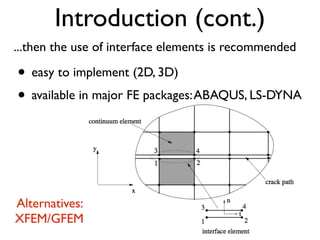


![Numerical integration
It has been observed numerically that integrating the
internal force and stiffness matrix of interface elements
using the standard Gauss rule led to oscillatory response
[de Borst, IJNME, 1993].
Newton-Cotes integration scheme
for interface elements](https://image.slidesharecdn.com/dgln2melqwmn9rhxs9od-signature-c97a7b5f56f24f40845160fd6fb6cc22ae00d12314cbbb86b38fb7fc761e4483-poli-141203191054-conversion-gate01/85/Interface-cohesive-elements-for-fracture-modeling-10-320.jpg)

![Energy control
✏ = Ba BT
Gutierrez 2004 equilibrium
V =
1
2
Z
⌦
✏T =
1
2
Z
⌦
aTBT =
1
2
aTf int =
1
2
aTg
Energy release rate a˙Tg
˙V
f int =
Z
⌦
Arc-length function
predefined amount of energy
to be released [Nm]
forward Euler
G 0](https://image.slidesharecdn.com/dgln2melqwmn9rhxs9od-signature-c97a7b5f56f24f40845160fd6fb6cc22ae00d12314cbbb86b38fb7fc761e4483-poli-141203191054-conversion-gate01/85/Interface-cohesive-elements-for-fracture-modeling-16-320.jpg)

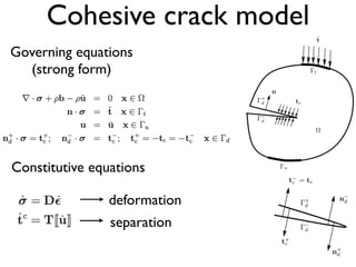
![Indirect displacement
control [de Borst 1986]
imagine what if
there are 2 cracks???
SEN beam
Indirect displacement control
(||uA uB|| ,l) local quantity!!!](https://image.slidesharecdn.com/dgln2melqwmn9rhxs9od-signature-c97a7b5f56f24f40845160fd6fb6cc22ae00d12314cbbb86b38fb7fc761e4483-poli-141203191054-conversion-gate01/85/Interface-cohesive-elements-for-fracture-modeling-18-320.jpg)


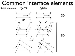
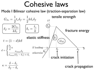
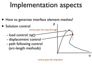
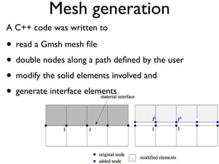
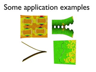
This document discusses using zero-thickness interface elements to model cracks in finite element analysis. It introduces interface elements and cohesive crack models, describes how to formulate and implement them in finite element codes, and provides some examples of their use. Key aspects covered include discrete equations for interface elements, numerical integration techniques, cohesive laws, solution procedures like load control and energy control path following methods, and examples applying interface elements to material debonding and delamination problems.


