Download as PDF, PPTX


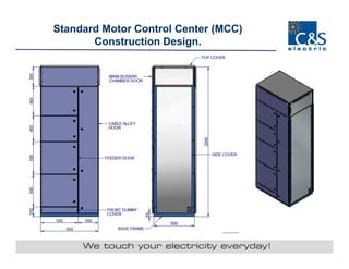


The document outlines specifications and construction details for various power control and motor control center panels, including features such as fully bolted trolleys, modular design, and robust safety mechanisms. It includes dimensions, operational ratings, and material specifications relevant to low voltage switchgear products. Additionally, it provides a cost analysis for equipment and panel assembly pertinent to a project by Ahluwalia Contracts in New Delhi.


![external_project presentation tt[1].pptx](https://cdn.slidesharecdn.com/ss_thumbnails/externalproject1-250611171730-49e3dd03-thumbnail.jpg?width=640&height=640&fit=bounds)


