Downloaded 60 times


![Installation Space
Installation Space
• The following values are the least space for installation.
If any service area is needed for service according to field circumstance, obtain enough service space.
• The unit of values is mm.
■ In case of obstacles on the suction side
1. Stand alone installation
10
mo 0 or
r re
0o 10 0o
r
10 ore mo 0 or 10 ore
m re m
les
s ss
r o r le
0o 00
50 5
1000 or
more
1000 or
more
15
r mo0 or
0o re
10 ore 15 0o
r
m mo0 or 15 ore
re m
[Unit:mm]
2. Collective installation
ss
r le
0o
1000 or
50
more
10 10
0 0
mo 0 or mo 0 or
re 10 re 10
mo 0 or mo 0 or
re re r
20
0o
r 20 0o
mo 0 or 30 ore mo 0 or
30 ore
m
re m re
[Unit:mm]
12 Outdoor Unit](https://image.slidesharecdn.com/installationmanualmini-130122114709-phpapp02/85/Installation-manual-mini-12-320.jpg)
![Installation Space
■ In case of obstacles on the discharge side
ENGLISH
1. Stand alone installation s
les
0 or
50
1000 or
more
re re
r mo r mo
0o 0o
50 50
s
les
0 or
2. Collective installation 50
1000 or more
10 10
mo 0 or mo 0 or
re re
re ore
r mo o rm
00o 10
00
10 [Unit:mm]
■ In case of obstacles on the suction and the discharge side
➲ Obstacle height of discharge side is higher than the unit
ss
1. Stand alone installation o r le
500
L>H L>H
1000 or
more
H
L
L
H
r
r 0o
0o 25 ore
10 ore or m
00
r
m 10 ore [Unit:mm]
0o e m
50 mor
Installation Manual 13](https://image.slidesharecdn.com/installationmanualmini-130122114709-phpapp02/85/Installation-manual-mini-13-320.jpg)
![Installation Space
2. Collective installation
s
les
0 or
50
1000 or
L>H L>H
more
H
L
10
L
0o 10
rm 0o
ore rm
r ore r
0o 0o
30 ore 30 ore
m m
ore
or orm
00 50
10 more 12
[Unit:mm]
➲ Obstacle height of discharge side is lower than the unit
1. Stand alone installation ss
r le
0o
50
1000 or
more
L≤H L≤H
H
H
L
L
r
0o
r 30 ore
0o or m
10 ore 00
r m 10 ore
0o m
50 ore
m
2. Collective installation
s
les
0 or
1000 or
more
50
L≤H L≤H
H
H
L
L
10 10
0o 0o
rm rm
ore ore
r or
0o 00
30
r more or 3 more
0o 00
150 ore 15 more [Unit:mm]
m
14 Outdoor Unit](https://image.slidesharecdn.com/installationmanualmini-130122114709-phpapp02/85/Installation-manual-mini-14-320.jpg)
![Installation Space
Collective / Continuous Installation for roof top use
ENGLISH
Space required for collective installation and continuous installation: When installing several units, leave space
between each block as shown below considering passage for air and people.
1. One row of stand alone installation
or
100 ore
r m
0o
200 ore
m
or
200 ore
r m
0o
100more [Unit:mm]
2. Rows of collective installation (2 or more)
• L should be smaller than H
L≤H
10
mo 0 or
L
re
or
300ore
r m
0o
300more
H
or
r 600ore
0o m
150 ore [Unit:mm]
m
Seasonal wind and cautions in winter
• Sufficient measures are required in a snow area or severe cold area in winter so that product can be operated well.
• Get ready for seasonal wind or snow in winter even in other areas.
• Install a suction and discharge duct not to let in snow or rain.
• Install the outdoor unit not to come in contact with snow directly. If snow piles up and freezes on the air suction hole,
the system may malfunction. If it is installed at snowy area, attach the hood to the system.
• Install the outdoor unit at the higher installation console by 50cm than the average snowfall (annual average snowfall) if
it is installed at the area with much snowfall.
1. The height of H frame must be more than 2 times the snowfall and its width shall not exceed the width of the
product. (If width of the frame is wider than that of the product, snow may accumulate)
2. Don't install the suction hole and discharge hole of the Outdoor Unit facing the seasonal wind.
Installation Manual 15](https://image.slidesharecdn.com/installationmanualmini-130122114709-phpapp02/85/Installation-manual-mini-15-320.jpg)
![Installation
Installation
Foundation for Installation
• Check the strength and level of the installation ground so that the unit will not cause any operating vibration or
noise after installation.
• Fix the unit securely by means of the foundation bolts. (Prepare 4sets of M12 foundation bolts, nuts and
washers each which are available on the market.)
• It is best to screw in the foundation bolts until their length are 20mm from the foundation surface.
Anti-vibration
Spring washer materials
Frame Nut Concrete Four bolt are
base required
H-Beam 3 thread ridges
75
75
200
200
100
[Unit:mm]
Foundation bolt executing method
16 Outdoor Unit](https://image.slidesharecdn.com/installationmanualmini-130122114709-phpapp02/85/Installation-manual-mini-16-320.jpg)
![Installation
Preparation of Piping
ENGLISH
Main cause of gas leakage is defect in flaring work. Carry out correct flaring work in the following procedure.
1) Cut the pipes and the cable. Copper
■ Use the accessory piping kit or the pipes purchased tube 90° Slanted Uneven Rough
locally.
■ Measure the distance between the indoor and the
outdoor unit.
■ Cut the pipes a little longer than measured distance.
■ Cut the cable 1.5m longer than the pipe length.
Pipe
Reamer
2) Burrs removal
■ Completely remove all burrs from the cut cross section
of pipe/tube. Point down
■ Put the end of the copper tube/pipe to downward
direction as you remove burrs in order to avoid to let
burrs drop in the tubing.
3) Flaring work
■ Carry out flaring work using flaring tool as shown right. Handle
Bar Bar
Unit : mm(inch) "A" Yoke
Indoor unit Pipe " A " Cone
[kW(Btu/h] Gas Liquid Gas Liquid
1.6~1.8 1.1~1.3
<5.6(19,100) 12.7(1/2) 6.35(1/4) Copper pipe
(0.63~0.71) (0.43~0.51)
1.6~1.8 1.5~1.7 Clamp handle
<16.0(54,600) 15.88(5/8) 9.52(3/8) Red arrow mark
(0.63~0.71) (0.59~0.67)
1.9~2.1 1.5~1.7
<22.4(76,400) 19.05(3/4) 9.52(3/8)
(0.75~0.83) (0.59~0.67)
Firmly hold copper tube in a bar(or die) as indicated
dimension in the table above. Smooth all round
Inside is shining without scratches.
4) Check
■ Compare the flared work with figure right. = Improper flaring =
■ If flare is noted to be defective, cut off the flared section
and do flaring work again.
Inclined Surface Cracked Uneven
damaged thickness
Even length
all round
Installation Manual 17](https://image.slidesharecdn.com/installationmanualmini-130122114709-phpapp02/85/Installation-manual-mini-17-320.jpg)


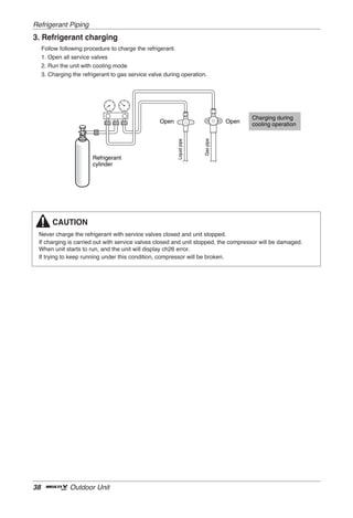
![Refrigerant Piping
Caution
ENGLISH
1. Use the following materials for refrigerant piping.
• Material: Seamless phosphorous deoxidized copper pipe
• Wall thickness : Comply with the relevant local and national regulations for the designed pressure
3.8MPa. We recommend the following table as the minimum wall thickness.
Outer diameter
6.35 9.52 12.7 15.88 19.05 22.2 25.4 28.58 31.8 34.9 38.1 41.3
[mm]
Minimum
0.8 0.8 0.8 0.99 0.99 0.99 0.99 0.99 1.1 1.21 1.35 1.43
thickness [mm]
2. Commercially available piping often contains dust and other materials. Always blow it clean with a dry inert
gas.
3. Use care to prevent dust, water or other contaminants from entering the piping during installation.
4. Reduce the number of bending portions as much as possible, and make bending radius as big as possible.
5. Always use the branch piping set shown below, which are sold separately.
Header
Y branch
4 branch 7 branch 10 branch
ARBLN01621 ARBLN03321 ARBL054 ARBL057 ARBL1010
ARBLN07121 ARBLN14521 ARBL104 ARBL107 ARBL2010
6. If the diameters of the branch piping of the designated refrigerant piping differs, use a pipe cutter to cut
the connecting section and then use an adapter for connecting different diameters to connect the piping.
7. Always observe the restrictions on the refrigerant piping (such as rated length, difference in height, and
piping diameter).
Failure to do so can result in equipment failure or a decline in heating/cooling performance.
8. A second branch cannot be made after a header. (These are shown by .)
A A
B
A To Outdoor Unit
B Sealed Piping
9. The Multi V will stop due to an abnormality like excessive or insufficient refrigerant. At such a time, always
properly charge the unit. When servicing, always check the notes concerning both the piping length and
the amount of additional refrigerant.
10. Never use refrigerant to perform an air purge. Always evacuate using a vacuum pump.
11. Always insulate the piping properly. Insufficient insulation will result in a decline in heating/cooling
performance, drip of condensate and other such problems.
12. When connecting the refrigerant piping, make sure the service valves of the Outdoor Unit is completely
closed (the factory setting) and do not operate it until the refrigerant piping for the Outdoor and Indoor
Units has been connected, a refrigerant leakage test has been performed and the evacuation process
has been completed.
13. Always blow nitrogen into pipe which is brazed. Always use a non-oxidizing brazing material for brazing
the parts and do not use flux. If not, oxidized film can cause clogging or damage to the compressor unit
and flux can harm the copper piping or refrigerant oil.
Installation Manual 23](https://image.slidesharecdn.com/installationmanualmini-130122114709-phpapp02/85/Installation-manual-mini-23-320.jpg)
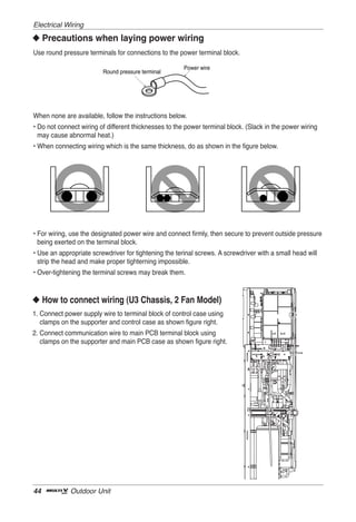
![Refrigerant Piping
Selection of Refrigerant Piping
ENGLISH
Outdoor unit
Gas pipe Liquid pipe
Branching
pipe
Main pipe
Branching Indoor unit
pipe
No. Piping parts Name Selection of pipe size
Size of main pipe
Liquid pipe Gas pipe
Outdoor unit capacity[kW(Btu/h)]
Outdoor unit [mm(inch)] [mm(inch)]
① Main pipe 11.0(37,500) Ø9.52(3/8) Ø15.88(5/8)
↓
1st branching section 14.5(49,500) Ø9.52(3/8) Ø15.88(5/8)
16.0(54,600) Ø9.52(3/8) Ø19.05(3/4)
Pipe size of between branching sections
Liquid pipe Gas pipe
Branching section Indoor unit capacity[kW(Btu/h)]
[mm(inch)] [mm(inch)]
② ↓ Branching pipe
≤ 5.6(19,100) Ø6.35(1/4) Ø12.7(1/2)
Branching section < 16.0(54,600) Ø9.52(3/8) Ø15.88(5/8)
< 22.4(76,400) Ø9.52(3/8) Ø19.05(3/4)
Connecting pipe size of indoor unit
Branching section Liquid pipe Gas pipe
Indoor unit Indoor unit capacity[kW(Btu/h)]
③ ↓
[mm(inch)] [mm(inch)]
connecting pipe
≤ 5.6(19,100) Ø6.35(1/4) Ø12.7(1/2)
Indoor unit
< 16.0(54,600) Ø9.52(3/8) Ø15.88(5/8)
Installation Manual 25](https://image.slidesharecdn.com/installationmanualmini-130122114709-phpapp02/85/Installation-manual-mini-25-320.jpg)


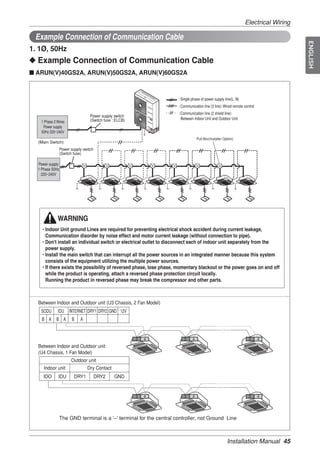
![Refrigerant Piping
■ Combination of Y branch/header method
Example : 5 Indoor Units connected
Ⓐ : Outdoor Unit
Ⓑ : 1st branch (Y branch)
Ⓒ : Y branch
Ⓓ : Indoor Unit
Ⓔ : Header
Ⓕ : Sealed piping
H 50m
L 150m
40m
Branch pipe can not be used after header
➲ Refrigerant pipe diameter from branch to branch (B,C)
Downward Indoor Unit total capacity Liquid pipe Gas pipe
[kW(Btu/h)] [mm(inch)] [mm(inch)]
≤ 5.6(19,100) Ø6.35(1/4) Ø12.7(1/2)
< 16.0(54,600) Ø9.52(3/8) Ø15.88(5/8)
< 22.4(76,400) Ø9.52(3/8) Ø19.05(3/4)
➲ Total pipe length = A+B+C+a+b+c+d+e ≤ 300m
Longest pipe length Equivalent pipe length(*)
L
A+B+b ≤ 150m A+B+b ≤ 175m
Longest pipe length after 1st branch
l
B+b ≤ 40m
Difference in height(Outdoor Unit ↔ Indoor Unit)
H
H ≤ 50m (40m : Outdoor Unit is lower than Indoor Units)
Difference in height (Indoor Unit ↔ Indoor Unit)
h h ≤ 15m
* : Assume equivalent pipe length of Y branch to be 0.5m, that of header to be 1m, calculation purpose
CAUTION
Indoor Unit should be installed at lower position than the header
WARNING
It is recommended that difference of piping length for pipes connected to the Indoor Unit is
minimized. Performance difference between Indoor Units may occur.
28 Outdoor Unit](https://image.slidesharecdn.com/installationmanualmini-130122114709-phpapp02/85/Installation-manual-mini-28-320.jpg)


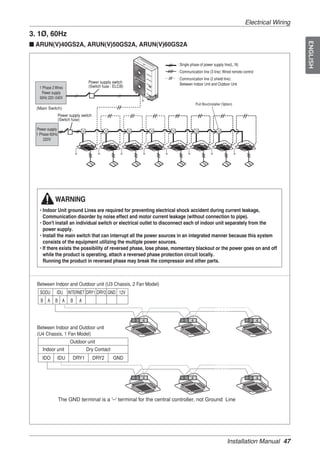
![Refrigerant Piping
Selection of Y Branch and Header
1. Y Branch
[unit:mm]
Models Gas pipe Liquid pipe
I.D12.7 I.D12.7
I.D15.88 I.D15.88 I.D.6.35 I.D9.52 I.D6.35
I.D9.52
1
I.D15.88 74
ARBLN01621 I.D12.7
I.D.6.35 74
I.D.9.52
281 281
292 292
I.D19.05 1 O.D9.52
O.D15.88
70 I.D12.7 70
I.D22.2 I.D19.05 I.D15.88 I.D19.05 I.D12.7
2 I.D12.7
1
I.D9.52 I.D9.52 I.D6.35
I.D19.05
I.D25.4 83
I.D15.88 I.D12.7
ARBLN03321 390 I.D12.7
I.D12.7
74
3 I.D9.52 I.D6.35
413
O.D19.05 I.D22.2 I.D28.58 O.D25.4
O.D19.05
I.D22.2 321
I.D25.4 332
3 1 2
70 80 110
I.D19.05 I.D19.05
I.D28.58 I.D22.2 I.D15.88 I.D12.7 I.D15.88 I.D15.88 I.D12.7
2 2
1
I.D12.7
I.D15.88 I.D19.05 I.D15.88 I.D19.05 83
I.D31.8 96
I.D19.05 I.D12.7
ARBLN07121
376 371 3
3
404 394
I.D28.58 I.D31.8 I.D34.9 O.D31.8 O.D19.05 I.D22.2 O.D12.7 I.D9.52 I.D6.35 O.D12.7 I.D9.52
I.D28.58
2 1 3 3 2
O.D22.2
120 90 120 110 70
I.D34.9
I.D41.3 I.D38.1 I.D28.58 I.D19.05
2 I.D15.88 I.D19.05 I.D22.2 I.D15.88
I.D34.9 2
1
I.D38.1 I.D28.58 I.D15.88
125 I.D22.2 I.D19.05 I.D12.7
I.D34.9 I.D22.2 96
471
ARBLN14521 3
416 3
517
444
I.D19.05 I.D15.88 O.D38.1 I.D41.3 O.D34.9 I.D38.1
3
2 3 I.D41.3
O.D22.2 I.D12.7 O.D19.05 I.D9.52
120 130 O.D15.88 I.D9.52 I.D22.2 O.D12.7 I.D6.35
90
I.D12.7 O.D28.58 I.D22.2 2 3 3
3
2 I.D19.05
O.D15.88 110 80 110
For example. Indicated Ø9.52 is the outer diameter(O.D..) of field jointed piping
34 Outdoor Unit](https://image.slidesharecdn.com/installationmanualmini-130122114709-phpapp02/85/Installation-manual-mini-34-320.jpg)
![Refrigerant Piping
ENGLISH
2. Header
[unit:mm]
Models Gas pipe Liquid pipe
360 360
120 120
ID12.7 ID6.35
ID12.7 ID6.35
4 branch
ID15.88 150 ID9.52 150
ARBL054 ID15.88 120 ID9.52 120
ID19.05 ID15.88 ID12.7 ID9.52
540 540
120 120
ID12.7 ID6.35
7 branch ID12.7
ID15.88 150 ID9.52
ARBL057 ID15.88 120 120 150
ID19.05 ID15.88
ID12.7 ID9.52
400 360
160 120
ID15.88 ID6.35
ID12.7 ID6.35
4 branch ID9.52
ID19.05 150 150
ID15.88 120 ID9.52 120
ARBL104
ID28.58 ID25.4 ID22.2 ID12.7 ID9.52
700
580
160 120
ID15.88 ID6.35
7 branch ID12.7 ID6.35
ID19.05 150 ID9.52 150
ARBL107 ID15.88 120 ID9.52 120
ID28.58 ID25.4 ID22.2
ID12.7 ID9.52
760 720
160
ID15.88
120
ID12.7 ID6.35
ID6.35
10 branch ID19.05 150
ID15.88 120 150
ARBL1010 ID9.52 120
ID28.58 ID25.4 ID22.2
ID9.52
ID12.7 ID9.52
700
775
182 60*9=540 107
ID15.88 ID6.35
10 branch ID12.7 ID6.35
ID19.05 150 150
ARBL2010 ID15.88 120 ID9.52 120
ID9.52 ID15.88 ID19.05
ID31.8 ID34.9 ID28.58
Installation Manual 35](https://image.slidesharecdn.com/installationmanualmini-130122114709-phpapp02/85/Installation-manual-mini-35-320.jpg)


![Electrical Wiring
■ Example Connection of Communication Cable
ENGLISH
[BUS type]
• Connection of communication cable must be installed like below figure between indoor unit to outdoor
unit.
[STAR type]
• Abnormal operation can be caused by communication defect, when connection of communication
cable is installed like below figure(STAR type).
Installation Manual 49](https://image.slidesharecdn.com/installationmanualmini-130122114709-phpapp02/85/Installation-manual-mini-49-320.jpg)


![Test Run
CAUTION
1. Guaranteed Temperature range(Error occurs out of guaranteed temperature range)
IDU : 20~32°C
ODU : 10~38°C
2. Set IDU wired remote controller temperature sensor setting as 'IDU'.
3. Make certain that IDU doesn't run with thermo off mode during operation.
[ Error contents about auto refrigerant charging function ]
1. : Temperature Range Error (In case that IDU or ODU is out of range)
2. : System Unstable Error (In case, After 45 min operating the system, it does not be stable)
How to cope with Result of Refrigerant Checking
1. If the temperature is not in guaranteed Temperature range, the system will not execute Refrigerant
checking and the system will be OFF.
2. Excess of Refrigerant(619)
After remove the 20% of calculated total refrigerant, recharge the refrigerant by using Refrigerant Auto
Charging Function.
3. Scarcity of Refrigerant(629)
Charge the refrigerant by using Refrigerant Auto Charging Function.
4. Impossible to Judge(639)
IF the system is not in order, check the other problem except refrigerant.
64 Outdoor Unit](https://image.slidesharecdn.com/installationmanualmini-130122114709-phpapp02/85/Installation-manual-mini-64-320.jpg)


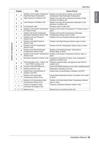


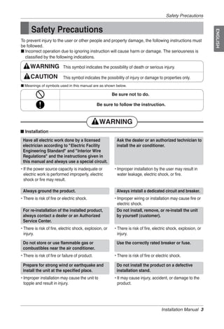
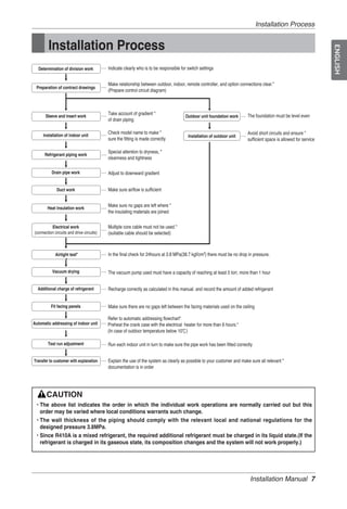
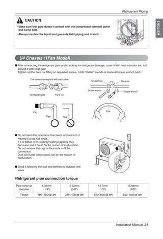
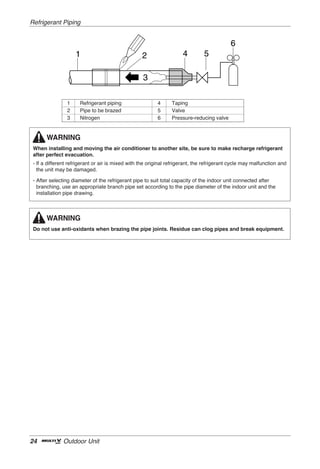
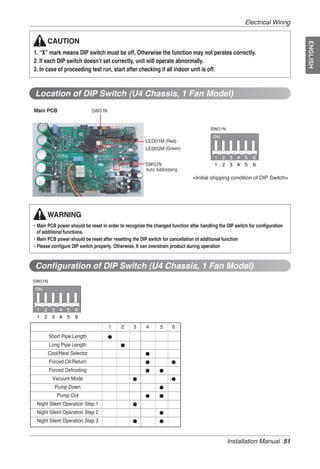
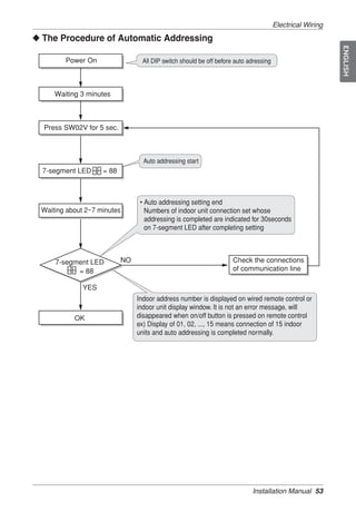
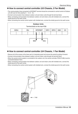
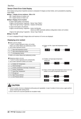
The document provides installation instructions for an air conditioner. It includes: - Safety precautions that must be followed to prevent injury and property damage during installation. - An installation process outline listing the order of installation steps. - Specifications for different outdoor unit models including dimensions, refrigerant amounts, and connection pipe sizes. - Instructions on site selection, unit installation, refrigerant piping, electrical wiring, test runs, and other installation procedures.


