Download to read offline
![LIQUID CHARGING METHOD — Add charge to the unit medium temperature brine unit, the cooler LCWT can go
through the liquid line service valve. Never charge liquid into down to 15 F (–9.4 C).
the low-pressure side of the system.
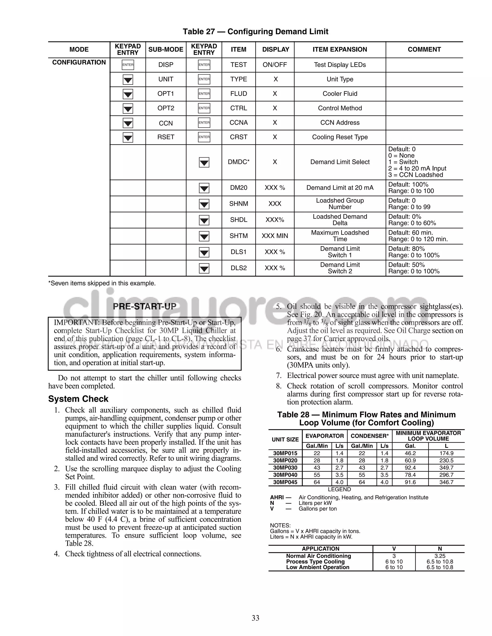
1. Close liquid line ball valve (30MPA only). Table 29 — Temperature Limits for
2. Connect a refrigerant cylinder loosely to the high flow Standard 30MP Units
Schraeder valve connection on the liquid line. Purge the TEMPERATURE LIMIT F C
charging hose and tighten the connections. Maximum Condenser LWT 140 60
3. Open the refrigerant cylinder valve. Minimum Condenser EWT 70 21
4. If the system has been dehydrated and is under vacuum, Maximum Cooler EWT* 95 35
break the vacuum with refrigerant gas. For R-410A, build Maximum Cooler LWT 70 21
up system pressure to 101 psig and 32 F (697 kPa and Minimum Cooler LWT† 40 4
0° C). Invert the refrigerant cylinder so that the liquid re-
frigerant will be charged. LEGEND
EWT — Entering Fluid (Water) Temperature
5. a. For complete charge of 30MPW units, follow LWT — Leaving Fluid (Water) Temperature
charging by weight procedure. When charge is
nearly full, complete the process by observing the *For sustained operation, EWT should not exceed 85 F (29.4 C).
†Unit requires modification below this temperature.
sight glass for clear liquid flow while the unit is
operating. The use of sight glass charging is valid
only when unit is operating at full capacity. CAUTION
b. For complete charge of 30MPA units or where Medium temperature brine duty application (below 32 F
refrigerant cylinder cannot be weighed, follow the [0° C] LCWT) for chiller normally requires factory modifi-
condenser manufacturer’s charging procedure or cation. Contact your Carrier representative for applicable
follow charging by sight glass procedure. The use LCWT range for standard water-cooled chiller in a specific
of sight glass charging is valid only when unit is application.
operating at full capacity.
6. a. The 30MPA condenserless units are shipped VOLTAGE — ALL UNITS
with a nitrogen holding charge. After installation Main Power Supply — Minimum and maximum acceptable
with the field-supplied system high side, the com- supply voltages are listed in the Installation Instructions.
plete system should be evacuated and charged per
the condenser manufacturer’s charging procedure Unbalanced 3-Phase Supply Voltage — Never operate a motor
or charged until the sight glass is clear (with the where a phase imbalance between phases is greater than 2%.
unit running at full capacity). To achieve maxi- To determine percent voltage imbalance:
mum system capacity, add additional charge equal a30-4979 max voltage deviation
to the difference between the condenser optimal from avg voltage
% Voltage Imbalance = 100 x
charge and the condenser minimum charge, which average voltage
can be obtained from the charge data provided in
the condenser installation instructions. The maximum voltage deviation is the largest difference
between a voltage measurement across 2 legs and the average
b. To ensure maximum performance of 30MPW across all 3 legs.
units, raise the compressor saturated discharge
temperature (SDT) to approximately 100 F Example: Supply voltage is 240-3-60.
(37.8 C) by throttling the condenser water intake. AB = 243 v
Add charge until there is approximately 9 to 12° F BC = 236 v
(5.0 to 6.6° C) of system subcooling (SDT minus AC = 238 v
actual temperature entering the thermostatic
expansion valve).
1. Determine average voltage:
Operating Limitations
243 + 236 + 238
TEMPERATURES (See Table 29 for 30MP standard tem- Average voltage =
perature limits). 3
717
CAUTION =
3
Do not operate with cooler leaving chiller water (fluid) = 239
temperature (LCWT) below 32 F (0° C) for standard units 2. Determine maximum deviation from average voltage:
with proper brine solution or 40 F (4.4 C) for the standard
(AB) 243 – 239 = 4 v
units with fresh water, or below 15 F (–9.4 C) for units fac- (BC) 239 – 236 = 3 v
tory built for medium temperature brine. (AC) 239 – 238 = 1 v
High Cooler Leaving Chilled Water (Fluid) Temperatures Maximum deviation is 4 v.
(LCWT) — During start-up with cooler the LCWT should not 3. Determine percent voltage imbalance:
be above approximately 60 F (16 C). 4
Low Cooler LCWT — For standard units with fresh water, % Voltage Imbalance = 100 x
239
the LCWT must be no lower than 40 F (4.4 C). For standard
units with a proper brine solution, the LCWT must be no lower = 1.7%
than 32 F (0° C). If the unit is the factory-installed optional
35](https://image.slidesharecdn.com/manualdeinstalacion-121001233404-phpapp01/75/Manual-de-instalacion-35-2048.jpg)
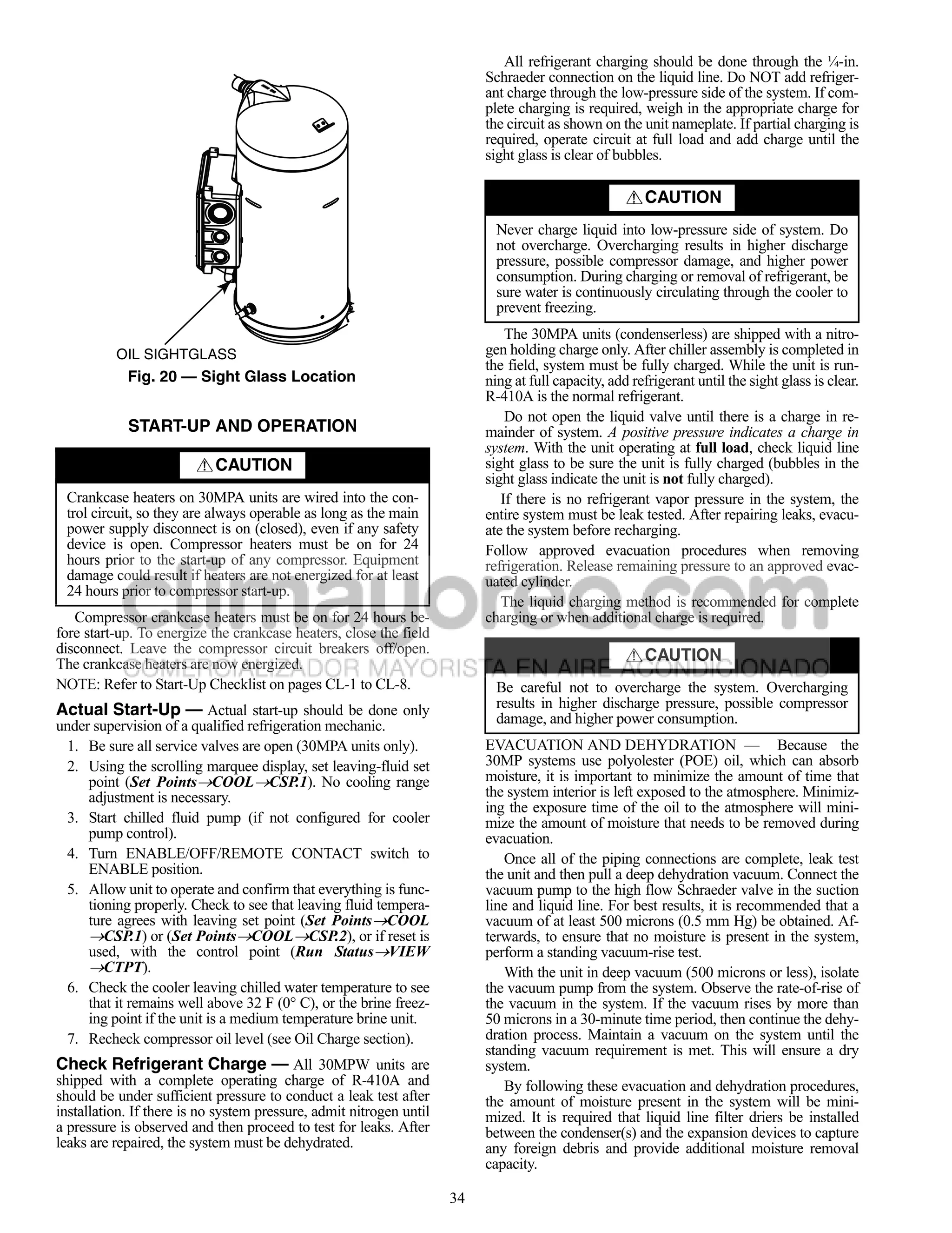
![MINIMUM LOAD VALVE — On units equipped with the COOLER FREEZE-UP PROTECTION
factory-installed hot gas bypass option, a solenoid valve and
discharge bypass valve (minimum load valve) are located WARNING
between the discharge line and the cooler entering-refrigerant
line. The MBB cycles the solenoid to perform minimum load On medium temperature brine units, the anti-freeze solu-
valve function and the discharge bypass valve modulates to the tion must be properly mixed to prevent freezing at a tem-
suction pressure set point of the valve. The bypass valve has an perature of at least 15 F (8.3 C) below the leaving-fluid
adjustable opening setting between 95 to 115 psig (655 to temperature set point. Failure to provide the proper anti-
793 kPa). The factory setting is 105 psig (724 kPa). freeze solution mixture is considered abuse and may impair
The amount of capacity reduction achieved by the mini- or otherwise negatively impact the Carrier warranty.
mum load valve is not adjustable. The total unit capacity with
the minimum load valve is shown in Table 19. The main base board (MBB) monitors cooler leaving fluid
PRESSURE RELIEF DEVICES — All units have one pres- temperature at all times. The MBB will rapidly remove stages
sure relief device per circuit located in the liquid line which re- of capacity as necessary to prevent freezing conditions due to
lieves at 210 F (100 C). the rapid loss of load or low cooler fluid flow.
The 30MPW unit does not have a condenser pressure relief When the cooler is exposed to lower temperatures (40 F
valve, because the brazed-plate condenser is not considered a [4.4 C] or below), freeze-up protection is required using inhib-
pressure vessel, as defined in ANSI/ASHRAE 15 (American ited ethylene or propylene glycol.
National Standards Institute/American Society of Heating,
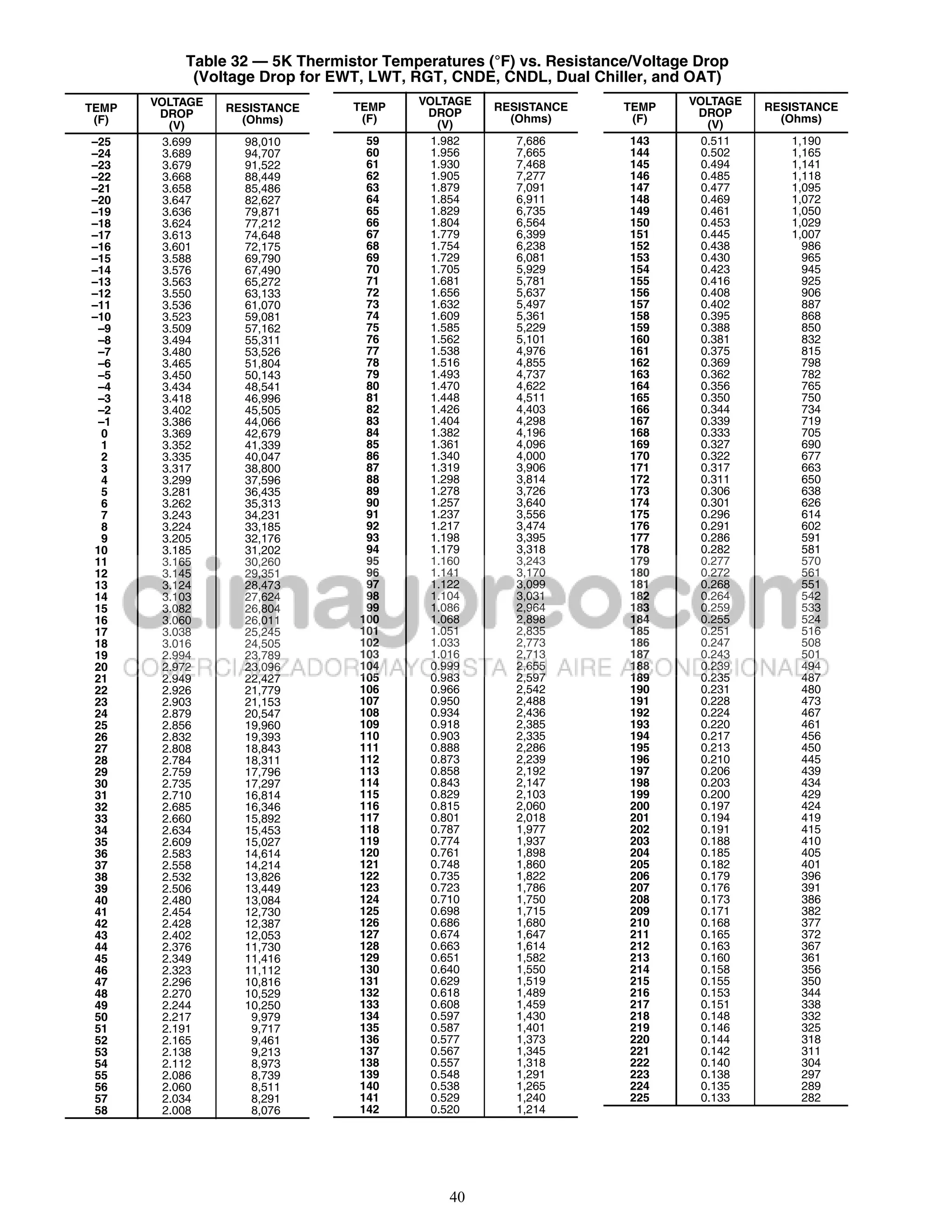
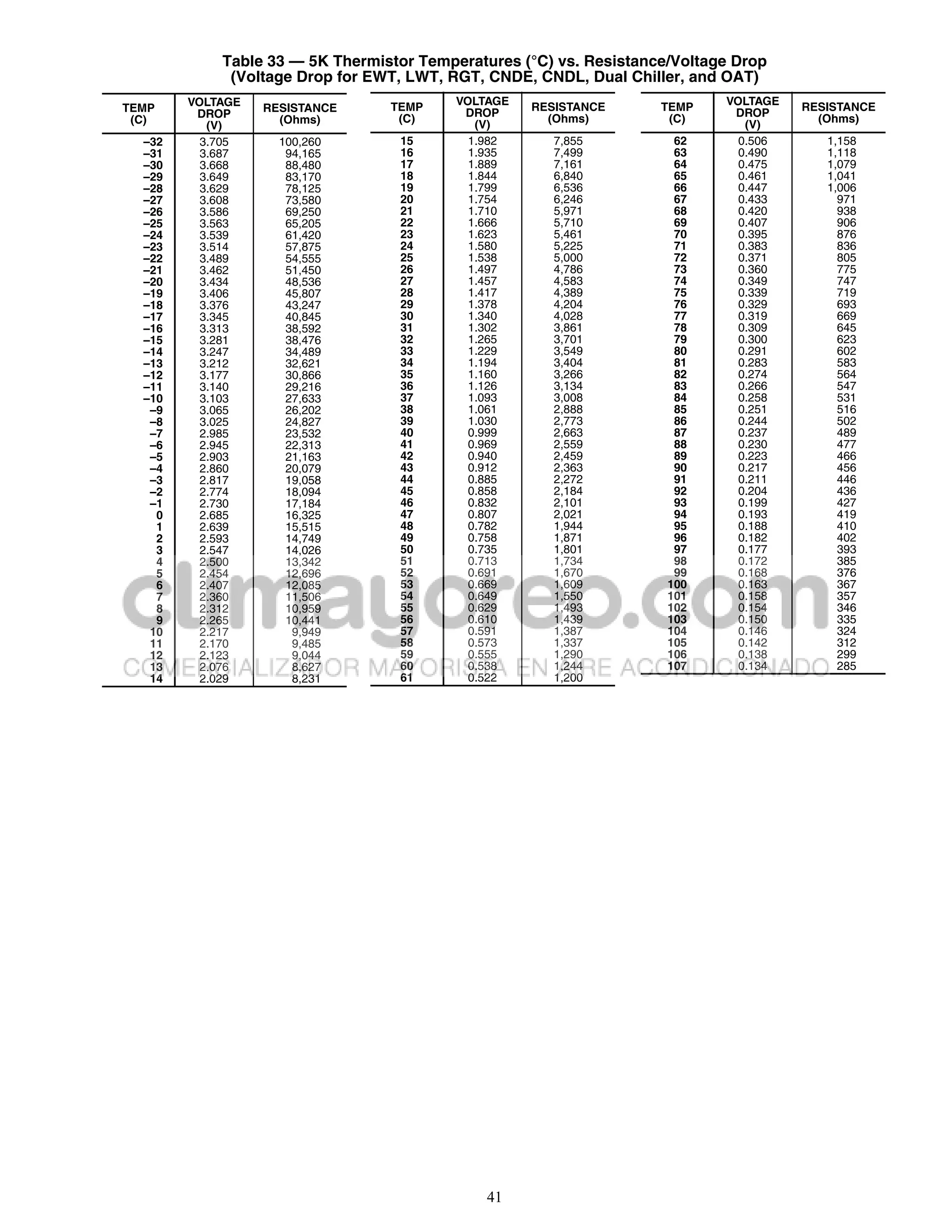
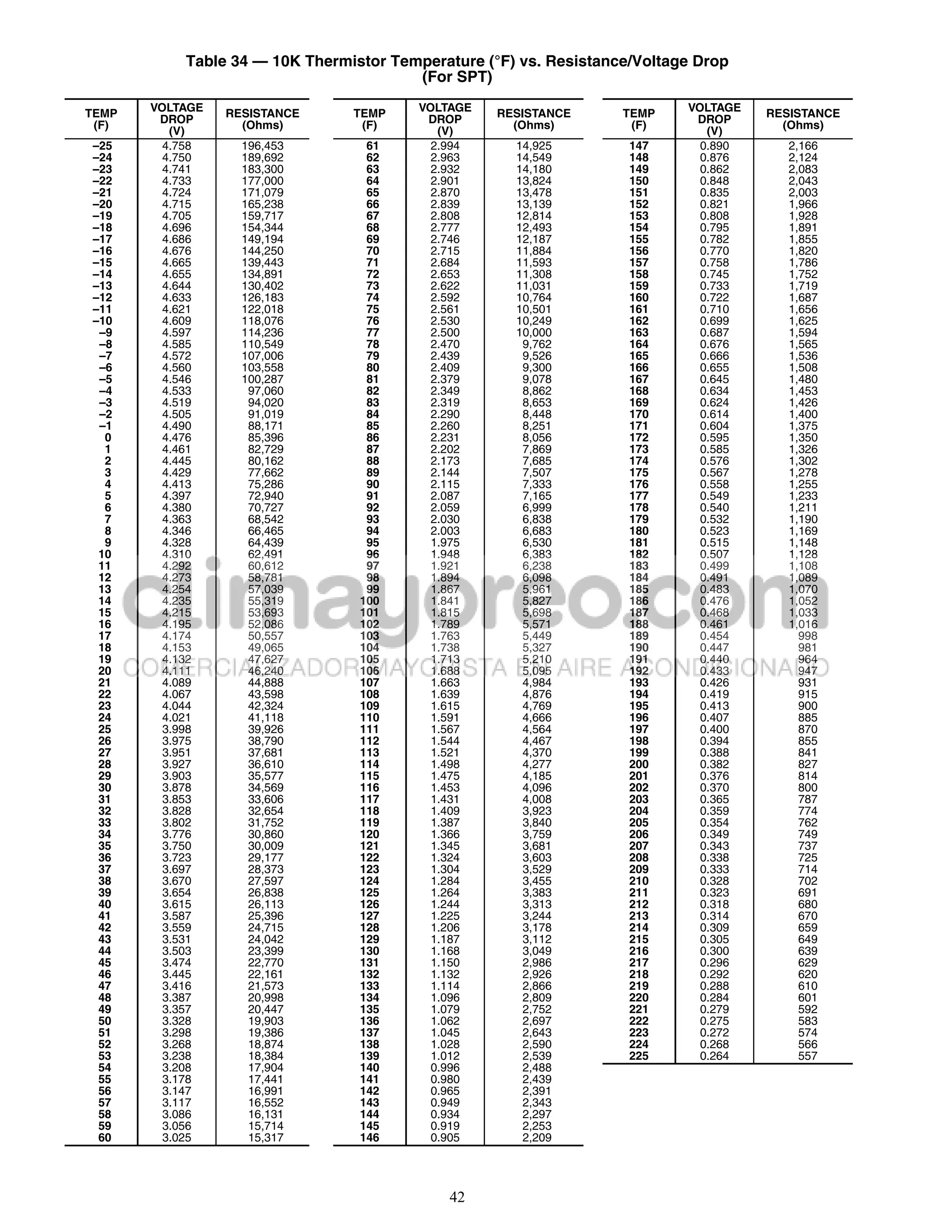
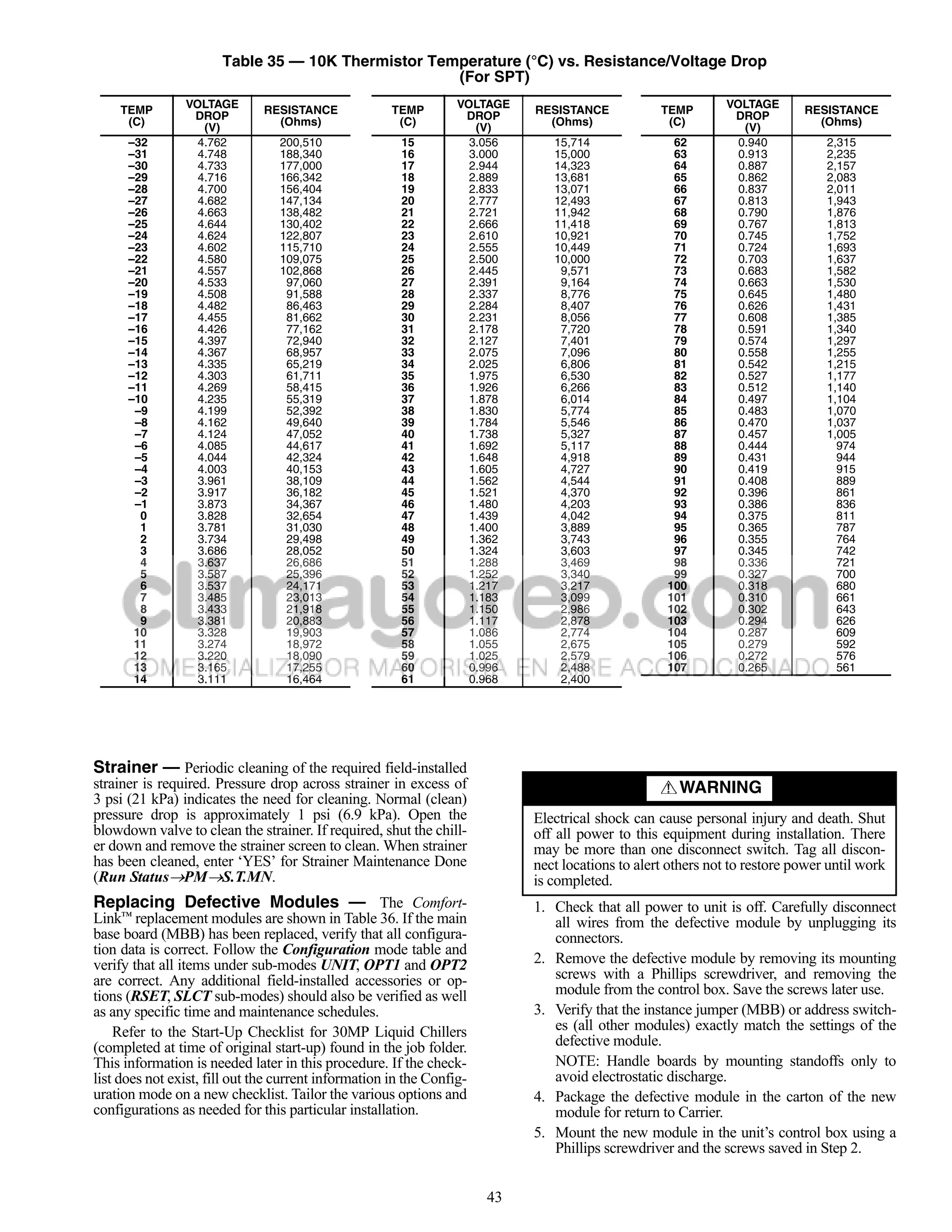
Refrigerating, and Air Conditioning Engineers) safety code Thermistors — Electronic control uses up to five 5 k
requirements. thermistors to sense temperatures used to control operation of
the chiller. Thermistors EWT, LWT, RGTA, CNDE, CNDL,
For 30MPA condenserless units, pressure relief devices de- and OAT are identical in their temperature and voltage drop
signed to relieve at the pressure determined in local codes, performance. The SPT space temperature thermistor has a
must be field-supplied and installed in the discharge line piping 10 k input channel and it has a different set of temperature vs.
in accordance with ANSI/ASHRAE 15 safety code require- resistance and voltage drop performance. Resistance at various
ments. Additional pressure relief valves, properly selected, temperatures are listed in Tables 32-35. For dual chiller opera-
must be field-supplied and installed to protect high side equip- tion, a dual chiller sensor is required which is a 5 k
ment and may be required by applicable codes. thermistor.
Most codes require that a relief valve be vented directly to REPLACING THERMISTORS (EWT, LWT, RGT, CNDE,
the outdoors. The vent line must not be smaller than the relief CNDL) — Add a small amount of thermal conductive grease
valve outlet. Consult ANSI/ASHRAE 15 for detailed informa- to the thermistor well and end of probe. For all probes, tighten
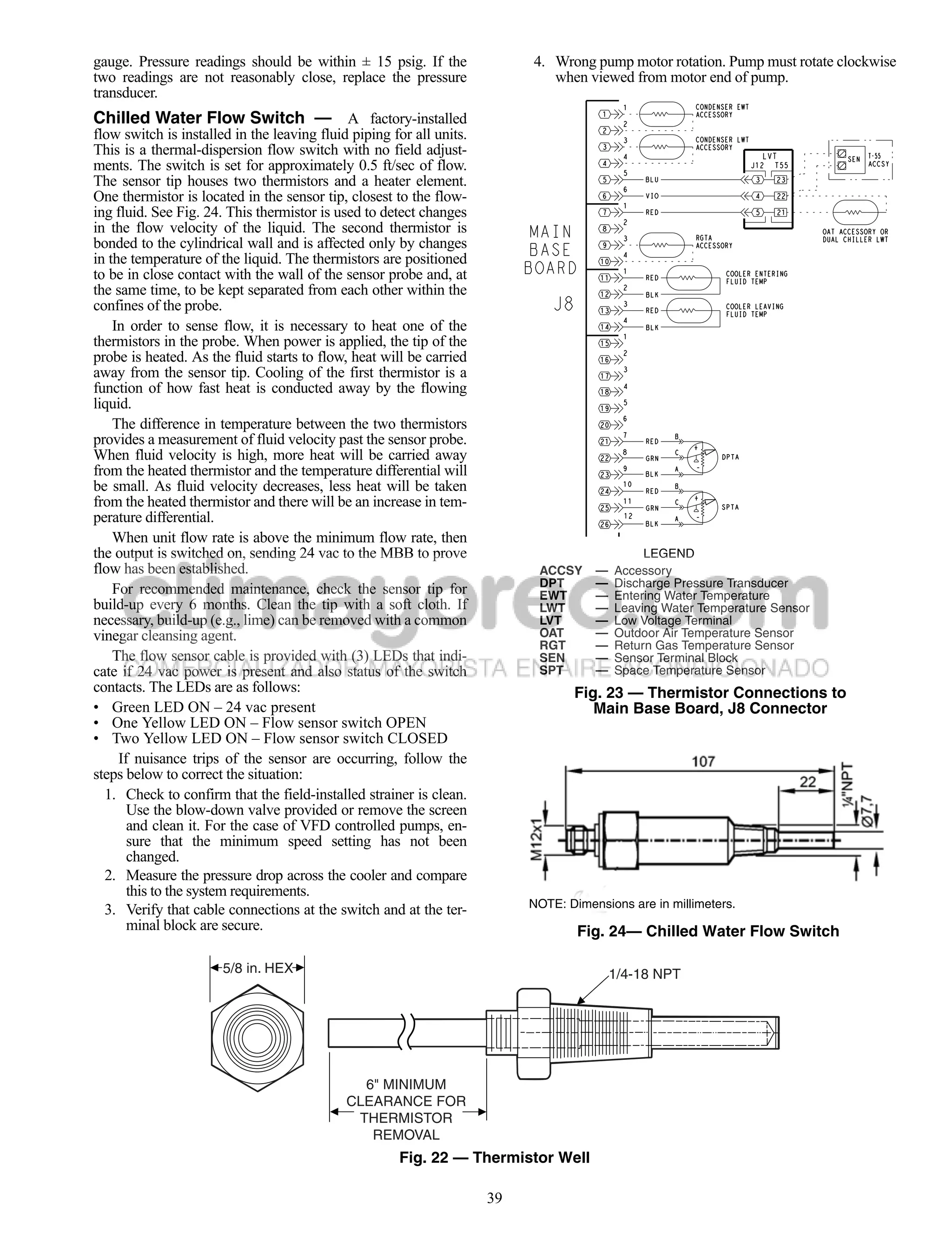
tion concerning layout and sizing of relief vent lines. the retaining nut ¼ turn past finger tight. See Fig. 22.
Check Unit Safeties THERMISTOR/TEMPERATURE SENSOR CHECK — A
HIGH-PRESSURE SWITCH — A high-pressure switch is high quality digital volt-ohmmeter is required to perform this
provided to protect each compressor and refrigeration system check.
from unsafe high pressure conditions. See Table 31 for high- 1. Connect the digital voltmeter across the appropriate the-
pressure switch settings. mistor terminals at the J8 terminal strip on the main base
board (see Fig. 23).
The high-pressure switch is mounted in the discharge line of
each circuit. If an unsafe, high-pressure condition should exist, 2. Using the voltage reading obtained, read the sensor tem-
the switch opens and shuts off the affected circuit. The CSB perature from Tables 32-35.
(current sensing board) senses the compressor feedback signal 3. To check thermistor accuracy, measure temperature at
and generates an appropriate alarm. The MBB prevents the cir- probe location with an accurate thermocouple-type tem-
cuit from restarting until the alert condition is reset. The switch perature measuring instrument. Insulate thermocouple to
should open at the pressure corresponding to the appropriate avoid ambient temperatures from influencing reading.
switch setting as shown in Table 31. Temperature measured by thermocouple and temperature
determined from thermistor voltage reading should be
Table 31 — Factory Settings, High-Pressure close, ± 5° F (3° C) if care was taken in applying thermo-
Switch (Fixed) couple and taking readings.
CUTOUT CUT-IN If a more accurate check is required, unit must be shut down
UNIT
Psig kPa Psig kPa and thermistor removed and checked at a known temperature
30MP015-045 650 4482 500 3447 (freezing point or boiling point of water) using either voltage
drop measured across thermistor at the J8 terminal, by deter-
Clear the alarm using the scrolling marquee display. The mining the resistance with chiller shut down and thermistor
unit should restart after the compressor anti-short-cycle delay, disconnected from J8. Compare the values determined with the
built into the unit control module, expires. value read by the control in the Temperatures mode using the
scrolling marquee display.
PRESSURE TRANSDUCERS — Each unit is equipped with
a suction and discharge pressure transducer. These inputs to the Pressure Transducers — The suction and discharge
MBB are not only used to monitor the status of the unit, but to transducers are different part numbers and can be distinguished
also maintain operation of the chiller within the compressor by the color of the transducer body, suction (yellow) and dis-
manufacturer's specified limits. The input to the MBB from the charge (red). No pressure transducer calibration is required.
suction pressure transducer is also used to protect the compres- The transducers operate on a 5 vdc supply, which is generated
sor from operating at low pressure conditions. If suction return by the main base board (MBB). See Fig. 23 for transducer con-
gas thermistors are installed, then additional low superheat nections to the J8 connector on the MBB.
conditions are detected. In some cases, the unit may not be able TROUBLESHOOTING — If a transducer is suspected of be-
to run at full capacity. The control module will automatically ing faulty, first check supply voltage to the transducer. Supply
reduce the capacity of a circuit as needed to maintain specified voltage should be 5 vdc ± 0.2 v. If supply voltage is correct,
maximum/minimum operating pressures. compare pressure reading displayed on the scrolling marquee
display module against pressure shown on a calibrated pressure
38](https://image.slidesharecdn.com/manualdeinstalacion-121001233404-phpapp01/75/Manual-de-instalacion-38-2048.jpg)


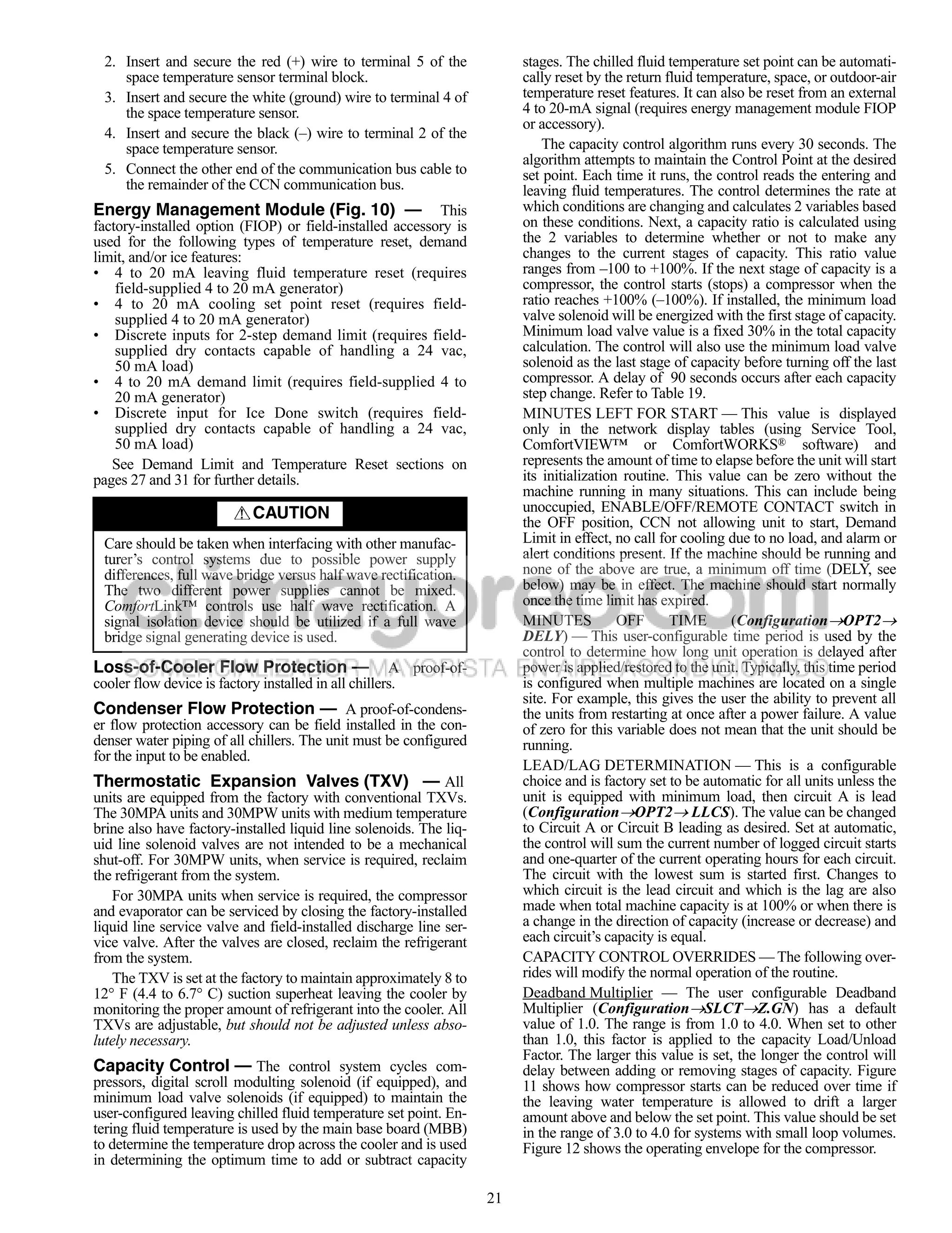
This document provides safety considerations, controls information, maintenance procedures, and troubleshooting steps for AquaSnap® 30MPA, MPW015-045 liquid chillers. It discusses hazards from system pressures, electrical components, and equipment location. Only trained installers and service technicians should work on the equipment. The controls use a microprocessor-based electronic system that could be damaged by jumpers or bypassing procedures. Maintenance includes checking unit safeties annually and replacing defective modules. Troubleshooting addresses issues like power failures, proof-of-flow switches, thermistor failures, and compressor safeties.


