Download as PDF, PPTX

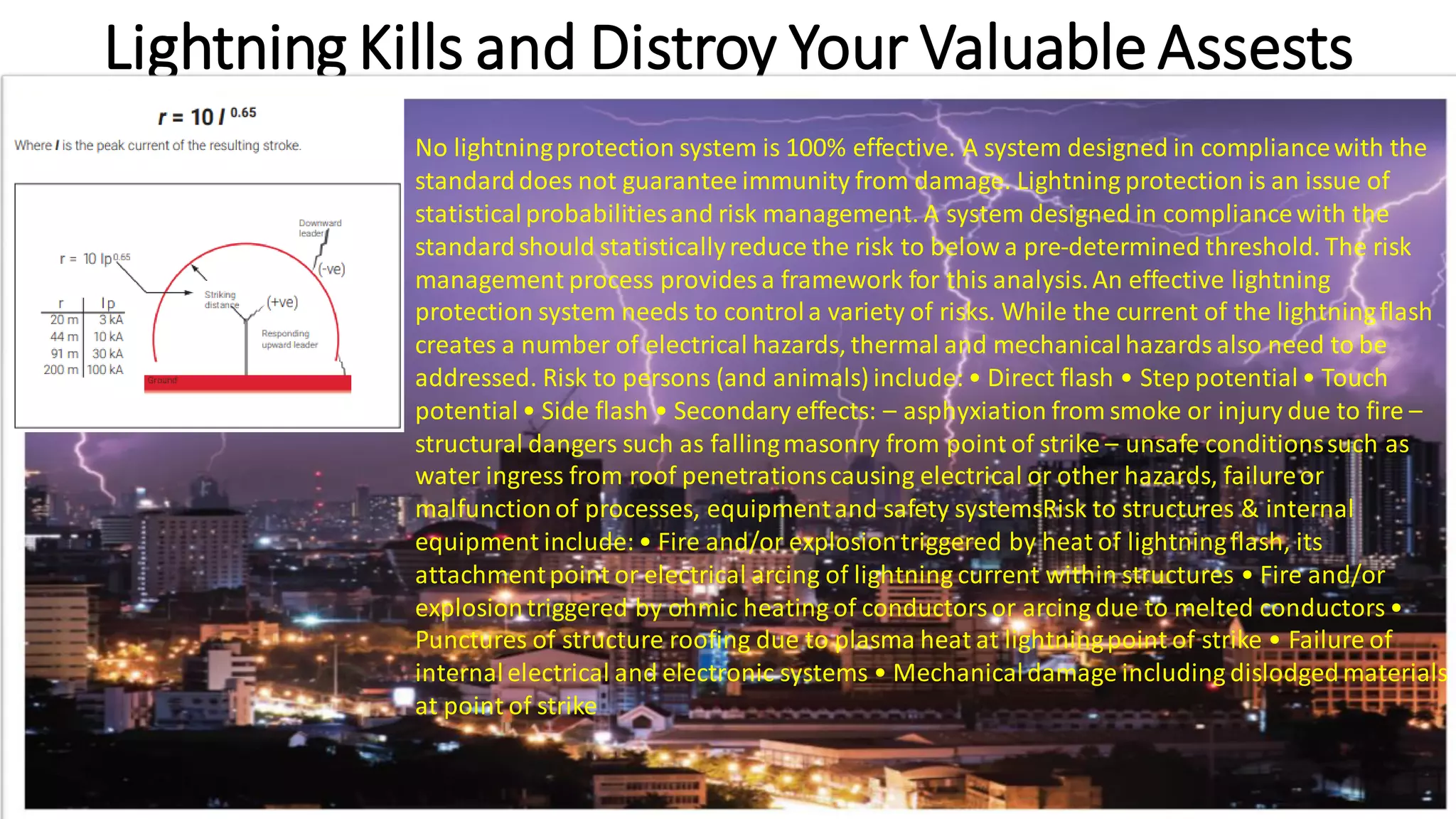
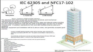

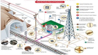

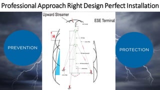

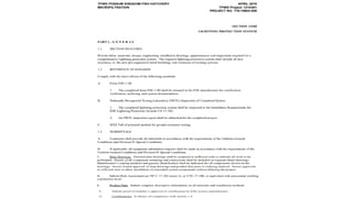
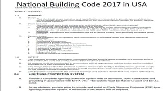
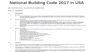
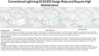
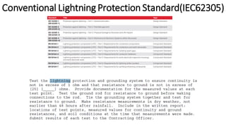
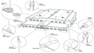
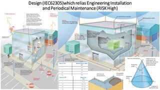
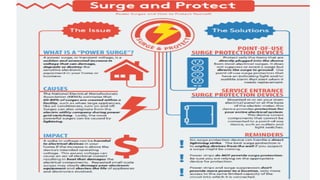
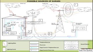
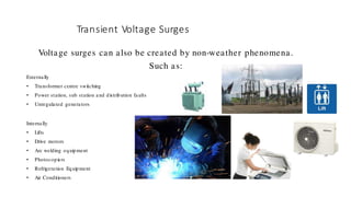
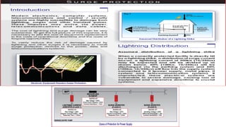
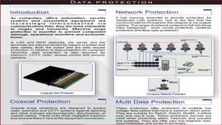


The document discusses the importance of lightning protection systems, emphasizing that no system can guarantee complete immunity from lightning damage, and effective risk management is crucial. It outlines various risks to people and structures, details components of lightning protection systems like lightning rods and down conductors, and highlights the differences between conventional and advanced protection systems. Additionally, it addresses surge protection, stressing the significance of using appropriate devices to safeguard sensitive electronic equipment from transient voltage surges.


