Download to read offline

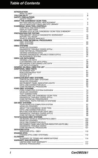


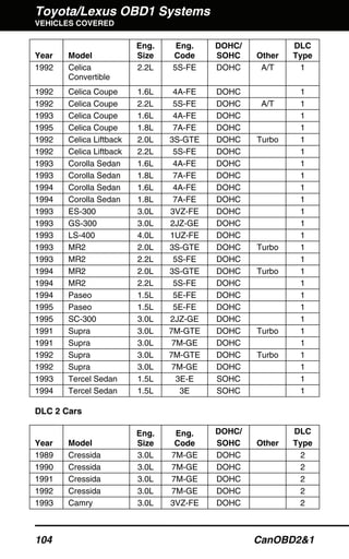


The document outlines the usage and features of the canobd2&1 scan tool, detailing its compatibility with OBD1 systems from Chrysler, Ford, GM, and Toyota, as well as all OBD2 compliant vehicles. It provides instructions on setup, safety precautions, battery replacement, and accessing diagnostic trouble codes (DTCs) through an extensive menu system. Additionally, it includes information on customizing display settings, searching DTC definitions, and the overall functionality of the scan tool in vehicle diagnostics.


![Motores tdi[1]](https://cdn.slidesharecdn.com/ss_thumbnails/motorestdi1-130612121625-phpapp01-thumbnail.jpg?width=640&height=640&fit=bounds)


![Mini Cooper Dashboard Warning Lights: Symbols and Meanings [FULL LIST]](https://cdn.slidesharecdn.com/ss_thumbnails/mini-cooper-warning-lights-221021084944-27b65ebd-thumbnail.jpg?width=640&height=640&fit=bounds)


![Toyota Dashboard Warning Lights [FULL]](https://cdn.slidesharecdn.com/ss_thumbnails/toyota-warning-lights-211126044903-thumbnail.jpg?width=640&height=640&fit=bounds)
![Mazda Dashboard Warning Lights: Symbols and Meanings [FULL LIST]](https://cdn.slidesharecdn.com/ss_thumbnails/mazda-warning-lights-221021085358-dcf733ba-thumbnail.jpg?width=640&height=640&fit=bounds)


