Downloaded 76 times
![Guidelines for Offshore Structural Reliability Page No. 28
-DNV Application to Jackup Structures
------------------------------------------------------------------------------------------------------------------------------------------------------------------------------------------------------------------------------------------------------------------------------------------------------------------------------------------------------------------------------------------------------------------------------------------------
Report No. 95-0072
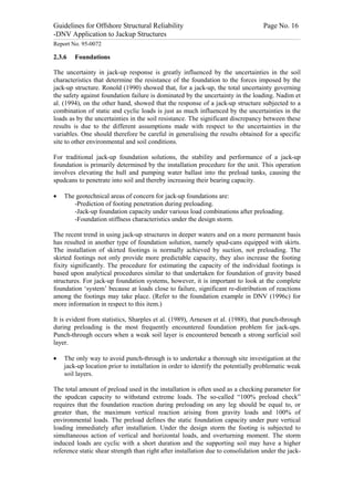
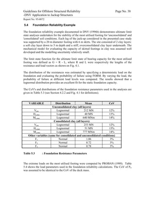
lengths derived from tests of frame structures until collapse are generally shorter than
those derived from theoretical calculations.
(iv) Different allowable requirements to fabrication tolerances (eccentricity) are
associated with the various buckling curves. For European buckling curves a
straightness deviation at the middle of the column equal to 0.0015 times the column
length is allowed, while for API (1993) and AISC (1984) the corresponding numbers
are 0.0010 and 0.00067 respectively.
For conventional design jack-up structural elements the effect of external pressure may,
normally be disregarded.
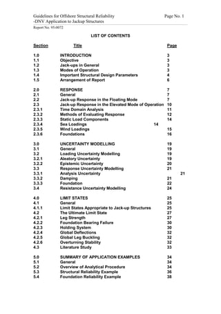
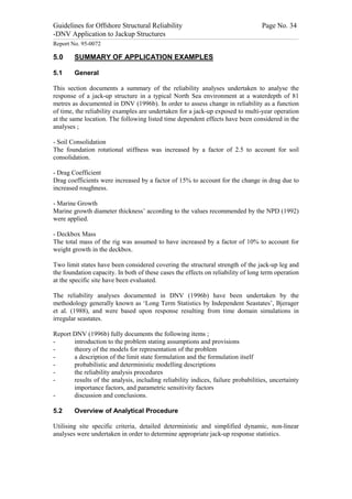
The susceptibility of local buckling of tubular members is a function of the member geometry
and yield strength. For jack-up structures, it may normally be assumed that leg elements are
stocky, beam elements. Yield strength control is implicitly covered by the buckling limit state
for members in compression, whilst, for tension members, the limit state is given by, for
example, eqn. 5.1, NPD (1990), NS3472 (1984).
G = fy - [ s a + s by + s bz ]2 + 3[ t xy + t xz + t t ]2 (5.1)
where
fy = material yield strength
sa = axial stress component
t t
= torsional shear stress component
sby , sbz = bending stress components
t xy , t xz = plain shear stress components
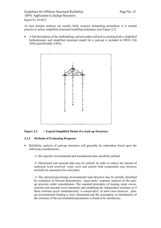
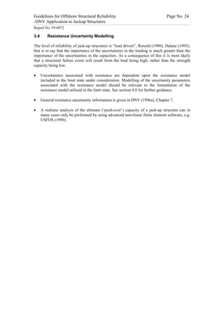
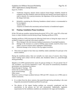
The capacity criterion stated in SNAME (1993) is an example of an expression applicable to
describe resistance of jack-up elements subjected to compressive loadings. Such formulation
may be described in the limit state format as ;
1
h h
Pu 8 éì M uex ü ì M uey ü ù
h
ï ï ú
G = 1 - X bias [ + êí ý +í ý ] (5.2)
Pn 9 êî M nx þ ï M ny ï ú
î þ û
ë
Where ;
Pu is the chord axial load
Pn is the chord nominal axial strength in compression
M uex is the chord local effective applied bending moment about the local x-axis
M uey is the chord local effective applied bending moments about the local y-axis
M nx is the chord local nominal bending strength about the local x-axis
M ny is the chord local nominal bending strength about the local y-axis
h is the exponent for biaxial bending.](https://image.slidesharecdn.com/jack-up-appl-120601071306-phpapp01/85/Download-28-320.jpg)
![Guidelines for Offshore Structural Reliability Page No. 29
-DNV Application to Jackup Structures
------------------------------------------------------------------------------------------------------------------------------------------------------------------------------------------------------------------------------------------------------------------------------------------------------------------------------------------------------------------------------------------------------------------------------------------------
Report No. 95-0072
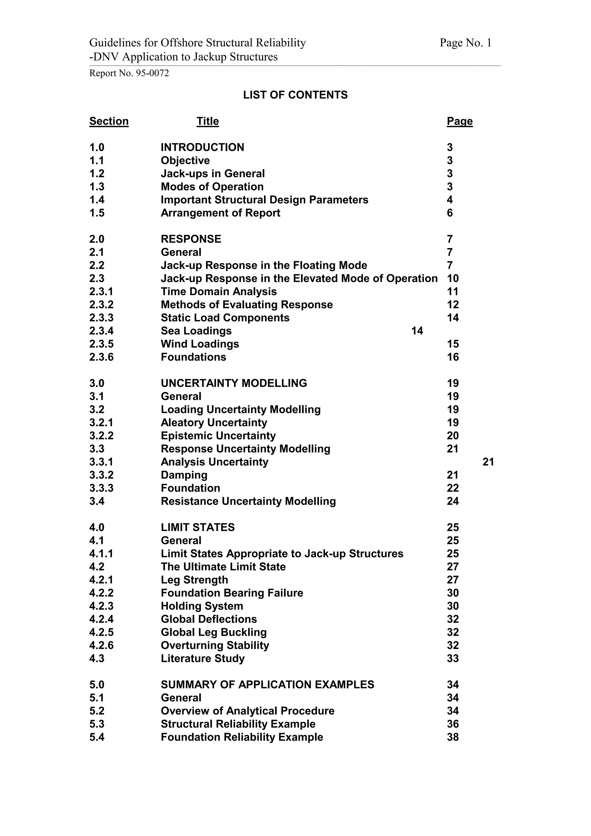
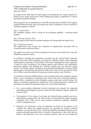
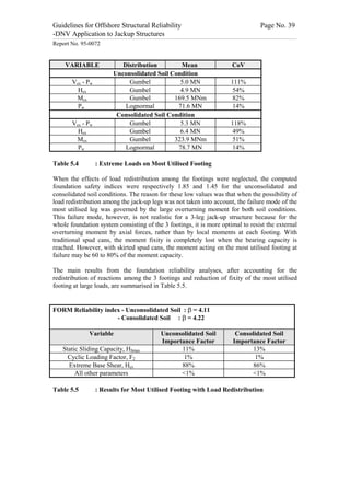
A full description of limiting criteria, the parameters utilised in Equation 5.2, and the
methodology utilised in calculating the specific values of these terms are documented in
SNAME (1993), Section 8.1.4.
The SNAME (1993) formulation for buckling resistance is based upon AISC (1978). The
uncertainty parameters stated in Galambos (1988) may therefore be utilised in describing the
uncertainty parameters including Xbias.
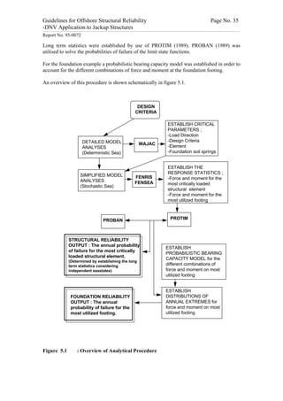
Joint Capacity
Joint capacity design equations have been established for the static strength of tubular joints.
The equations in API (1993) and NPD (1990) show a similar shape although the coefficients
are different as also might be expected as the API (1993) are based on allowable stresses and
NPD (1990) has based the design on the partial coefficient method.
Jack-up brace/chord connections are, however, normally non-standard, due to the rack
structure inclusion in the chord section. Static strength capacity formulation for standard
tubular/tubular connections may give erroneous results for brace/chord connections.
Work on joint capacities is currently being performed in development of a new ISO standard
on design of steel offshore structures. This work should be considered as basis for limit state
functions when it is available.
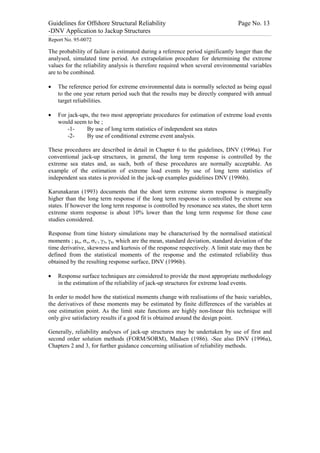
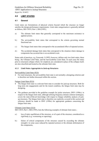
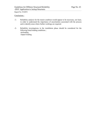
As an example limit state Eqn 5.3 documents the static strength of tubular joints formulation
based on the NPD guidelines, NPD (1990) and the limit state function for the static capacity
of tubular joints can then be formulated, NPD(1990) as ;
2
N æ M IP ö M
G = 1 - X bias [ +ç ÷ + OP ]
N k è M IPk ø M OPk (5.3)
where
Xbias = bias (See DNV (1996a), Chapter 7.2)
N = brace axial force
Nk = characteristic capacity of the brace subjected to axial force
M IP = brace in-plane moment
M IPk = characteristic capacity of the brace subjected to in-plane moments
M OP = brace out-of-plane moment
M OPk = characteristic capacity of the brace subjected to out-of-plane moments
A detailed description of this limit state is given in DNV (1996c).](https://image.slidesharecdn.com/jack-up-appl-120601071306-phpapp01/85/Download-29-320.jpg)

This document provides guidelines for analyzing the structural reliability of offshore jackup structures. It describes the different operational modes of jackups, including floating during transit and elevated during operation. For elevated conditions, it discusses modeling responses, uncertainties, limit states, and provides two example reliability analyses. For floating conditions, it notes key risks and limited available data, recommending referring to ship/barge reliability metrics when assessing strength. The document aims to enable Level III structural reliability analyses of jackup structures.


