Download to read offline
![International Research Journal of Engineering and Technology (IRJET) e-ISSN: 2395-0056
Volume: 09 Issue: 11 | Nov 2022 www.irjet.net p-ISSN: 2395-0072
© 2022, IRJET | Impact Factor value: 7.529 | ISO 9001:2008 Certified Journal | Page 600
Implementation of CAN on FPGA for Security Evaluation Purpose
Student, Dept. of Electronics Engineering,
Shri Ramdeobaba College of Engineering and Management, Nagpur, Maharashtra, India
---------------------------------------------------------------------***---------------------------------------------------------------------
Abstract - Controller Area Network (CAN) is a low-cost
communication protocol which is being used in various
applications like automotive, medical, military, aviation, etc.
Current CAN applications are based on the standard CAN 2.0
protocol. It was not designed for secure communication;
although, it offers built-in error detection, robustness, speed
and flexibility, the security side of CAN communication is
highly underdeveloped. Research on in-vehicle CAN security
primitives is difficult as it is hard to get a real vehicle for
evaluation and development of these security primitives. The
cost of research is considerably high, for some researchersthis
creates a barrier, acting as a deterrence. This paper presents
implementation of CAN on FPGA and evaluation of
cryptographic algorithms as a security measure in CAN bus
communication.
Key Words: FPGA, CAN bus, SJA1000, Xilinx Zynq,
PetaLinux, ZYBO, Evaluation, Security.
1. INTRODUCTION
If we consider only automobiles, there could be as many as
100 Electronic Control Units (ECUs) all communicating
through a single CAN bus system. Despite the functional
benefits, the CAN bus system is vulnerable to cyber-attacks
like replay attacks, denial-of-service,andman-in-the-middle
attacks. Security of any network can be assessed on three
attributes: confidentiality, integrity, andauthentication.Many
researchers have demonstrated various successful attacks
which showed that CAN bus fails in all these three
parameters [2,17,13]. Manufacturers understand these
vulnerabilities and have started implementing security
measures like, Network Segmentation, Intrusion Detection
System, Software-based encryption methods. But all these
are computation intensive, have their own vulnerabilities,
and are slower, thus reducing the data transferrateofsucha
time-critical system. And as pointed out by [3], considering
the lifetime of a vehicle, it is possibletofindvulnerabilities in
above mentioned measures and crack a static encryption
key. For high stake applications like military-equipment,
vehicles, aircraft such vulnerabilities are not acceptable. A
lot of research has been done in securing CAN
communications[14-18];however,these proposedsolutions
have their own limitations and vulnerabilities. Developing a
system that is able to meet resource constraints put by CAN
communication system is a real challenge. ModerndayECUs
are relatively efficient and fast compared to the ones used a
decade ago, hence some of the solutions proposed by some
authors could be a viable option with some performance
enhancing tweaks. However, a thorough evaluation of these
proposed methods is needed in order to explore the areasof
improvements. This is a laborious, complicated and time-
consuming process, to streamline this process a versatile
test-bed is needed that speeds up the entire chain of
implementation, evaluation, and development and
deployment. FPGAs based solutions can help to address
these challenges by enabling trueflexibilityandscalabilityto
address the security requirements of CAN bus with inherent
hardware and software programmability. Rather than
creating a bare-metal application to run on FPGA emulated
CAN controller, we rely on a test-bed thatrunsa light-weight
Linux kernel on top. Bare-metal application are difficult to
debug as there are no fault management and error
notifications unless they have been explicitly implemented
and validated. Given the scope of ourapplicationitisdifficult
to figure out what exactly could go wrong, hence the need of
a test-bed that has error handling and prompting abilities is
needed, this allows for speedy debugging and evaluation of
the proposed solutions, and speed up the development of
new ones. In our experimental test-bed, we have used
OpenCores SJA1000 controller, that has been modified to
ignore CAN FD frames. This version of SJA1000 is modified
by Czech Technical University, Prague (CTU) [1] and allows
this controller to co-exist and send data on CAN FD network.
2. SYSTEM DESIGN
The test-bed is built in two parts: hardware and software.
The design of hardware is done using Xilinx Vivado Design
Suite and is implemented on ZYBO (ZYnq BOard) that uses
Zynq All Programmable System on Chip Architecture. The
SoC design has two subsystems: Processing System (PS) and
Programmable Logic(PL).ThePS,isZynq-7000,hassoftware
programmability features and takes over the job of
controlling and communicating with PL. PL is Xilinx Artix-7
FPGA with configurable ports and buses, and has hardware
modules that are being emulated. The software design is
done with the help of PetaLinuxSDKtostreamlineembedded
Linux development. This tool helps us to develop a Bootable
System Image that consists ofa custom CPU-optimizedLinux
kernel, device drivers and bootloader configurations. The
test-bed is now ready forfurther implementation,evaluation
and development of security measures for CAN bus
communications.Thissectionfurtherdiscussestheimportant
elements of hardware and software design.
Rohit Pawar](https://image.slidesharecdn.com/irjet-v9i1188-221208094852-e13e189b/85/Implementation-of-CAN-on-FPGA-for-Security-Evaluation-Purpose-1-320.jpg)
![International Research Journal of Engineering and Technology (IRJET) e-ISSN: 2395-0056
Volume: 09 Issue: 11 | Nov 2022 www.irjet.net p-ISSN: 2395-0072
© 2022, IRJET | Impact Factor value: 7.529 | ISO 9001:2008 Certified Journal | Page 600
Implementation of CAN on FPGA for Security Evaluation Purpose
Student, Dept. of Electronics Engineering,
Shri Ramdeobaba College of Engineering and Management, Nagpur, Maharashtra, India
---------------------------------------------------------------------***---------------------------------------------------------------------
Abstract - Controller Area Network (CAN) is a low-cost
communication protocol which is being used in various
applications like automotive, medical, military, aviation, etc.
Current CAN applications are based on the standard CAN 2.0
protocol. It was not designed for secure communication;
although, it offers built-in error detection, robustness, speed
and flexibility, the security side of CAN communication is
highly underdeveloped. Research on in-vehicle CAN security
primitives is difficult as it is hard to get a real vehicle for
evaluation and development of these security primitives. The
cost of research is considerably high, for some researchersthis
creates a barrier, acting as a deterrence. This paper presents
implementation of CAN on FPGA and evaluation of
cryptographic algorithms as a security measure in CAN bus
communication.
Key Words: FPGA, CAN bus, SJA1000, Xilinx Zynq,
PetaLinux, ZYBO, Evaluation, Security.
1. INTRODUCTION
If we consider only automobiles, there could be as many as
100 Electronic Control Units (ECUs) all communicating
through a single CAN bus system. Despite the functional
benefits, the CAN bus system is vulnerable to cyber-attacks
like replay attacks, denial-of-service,andman-in-the-middle
attacks. Security of any network can be assessed on three
attributes: confidentiality, integrity, andauthentication.Many
researchers have demonstrated various successful attacks
which showed that CAN bus fails in all these three
parameters [2,17,13]. Manufacturers understand these
vulnerabilities and have started implementing security
measures like, Network Segmentation, Intrusion Detection
System, Software-based encryption methods. But all these
are computation intensive, have their own vulnerabilities,
and are slower, thus reducing the data transferrateofsucha
time-critical system. And as pointed out by [3], considering
the lifetime of a vehicle, it is possibletofindvulnerabilities in
above mentioned measures and crack a static encryption
key. For high stake applications like military-equipment,
vehicles, aircraft such vulnerabilities are not acceptable. A
lot of research has been done in securing CAN
communications[14-18];however,these proposedsolutions
have their own limitations and vulnerabilities. Developing a
system that is able to meet resource constraints put by CAN
communication system is a real challenge. ModerndayECUs
are relatively efficient and fast compared to the ones used a
decade ago, hence some of the solutions proposed by some
authors could be a viable option with some performance
enhancing tweaks. However, a thorough evaluation of these
proposed methods is needed in order to explore the areasof
improvements. This is a laborious, complicated and time-
consuming process, to streamline this process a versatile
test-bed is needed that speeds up the entire chain of
implementation, evaluation, and development and
deployment. FPGAs based solutions can help to address
these challenges by enabling trueflexibilityandscalabilityto
address the security requirements of CAN bus with inherent
hardware and software programmability. Rather than
creating a bare-metal application to run on FPGA emulated
CAN controller, we rely on a test-bed thatrunsa light-weight
Linux kernel on top. Bare-metal application are difficult to
debug as there are no fault management and error
notifications unless they have been explicitly implemented
and validated. Given the scope of ourapplicationitisdifficult
to figure out what exactly could go wrong, hence the need of
a test-bed that has error handling and prompting abilities is
needed, this allows for speedy debugging and evaluation of
the proposed solutions, and speed up the development of
new ones. In our experimental test-bed, we have used
OpenCores SJA1000 controller, that has been modified to
ignore CAN FD frames. This version of SJA1000 is modified
by Czech Technical University, Prague (CTU) [1] and allows
this controller to co-exist and send data on CAN FD network.
2. SYSTEM DESIGN
The test-bed is built in two parts: hardware and software.
The design of hardware is done using Xilinx Vivado Design
Suite and is implemented on ZYBO (ZYnq BOard) that uses
Zynq All Programmable System on Chip Architecture. The
SoC design has two subsystems: Processing System (PS) and
Programmable Logic(PL).ThePS,isZynq-7000,hassoftware
programmability features and takes over the job of
controlling and communicating with PL. PL is Xilinx Artix-7
FPGA with configurable ports and buses, and has hardware
modules that are being emulated. The software design is
done with the help of PetaLinuxSDKtostreamlineembedded
Linux development. This tool helps us to develop a Bootable
System Image that consists ofa custom CPU-optimizedLinux
kernel, device drivers and bootloader configurations. The
test-bed is now ready forfurther implementation,evaluation
and development of security measures for CAN bus
communications.Thissectionfurtherdiscussestheimportant
elements of hardware and software design.
Rohit Pawar](https://image.slidesharecdn.com/irjet-v9i1188-221208094852-e13e189b/75/Implementation-of-CAN-on-FPGA-for-Security-Evaluation-Purpose-1-2048.jpg)
![International Research Journal of Engineering and Technology (IRJET) e-ISSN: 2395-0056
Volume: 09 Issue: 11 | Nov 2022 www.irjet.net p-ISSN: 2395-0072
© 2022, IRJET | Impact Factor value: 7.529 | ISO 9001:2008 Certified Journal | Page 601
2.1 Hardware Design
The hardware consists of SJA1000 controller, TJA1050
CAN trans-receiver, Zynq 7000 SoC, and other periphery
circuits required for implementation of test-bed. Multiple
instances of this test-bed can be used to connect and
communicate on a CAN bus line for analysis and evaluation
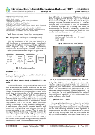
of different security measures. For the demonstration of
communication between two CAN nodes; Node1 and Node2
over the CAN bus, we perform a simple signal detection
experiment. When input is given to any one of the nodes by
pressing the switch, for instance consider Node1, CAN
communication is triggered and a data-framecorresponding
to the signal is transmitted over the CAN bus, this signal
data-frame is picked up by Node2, it interpretsitandtheLED
assigned to the switch, turns on or off. i.e., the LED of one
node is controlled by another node. Fig. 1 shows the block
diagram of a CAN node.
Fig -1: Block Diagram of Test-bed.
2.1.1 SJA1000
It is a stand-alone controller for the Controller Area
Network (CAN), mostly used within automotive and general
industrial environments. It has both CAN 2.0A (Standard
CAN) and 2.0B (Extended CAN) protocol support, with
bitrates up to 1 Mb/s. The SJA1000 that is used inthisproject
is CAN FD tolerant and is written in Verilog language [1]. It
contains transmission buffer (TXB), receiving buffer (RXB),
bit timing logic (BTL), acceptance filter (ACF), bit stream
processor (BSP), error management logic (EML), and
interface management logic (IML). It uses an APB interface
for on chip communication with master (i.e., the processing
system). SJA1000 appears to a master as a memory-mapped
I/O device. Independent operation of both devices is
guaranteed byaRAM-likeimplementationofitsregisters.Fig.
2 shows schematicdiagramoftheimplementedSJA1000CAN
controller.
Fig -2: Schematic of Implemented SJA1000 CAN
Controller
2.1.2 TJA1050 CAN transreceiver
It is an interface between CAN controller and physical
bus. It provides differential transmit and differential receive
capability to the CAN controller. It converts the Tx and Rx
signal of controller to CANH and CANL signal. It offers good
performance when it comes to optimal matching of output
signals (CANH, CANL). The figure below shows block
diagram of TJA1050.
2.1.3 Processing System
Zynq-7000 processing system (PS) is the master and an
instance of SJA1000 in PL is the slave. Communication
between master and slave on the SoC is done through AXI
and APB buses respectively. AXI is designed for
communication between blocks of IP on FPGA. AXI
interconnect IP is used to connect one or more AXI memory-
mapped master devices to one or more memory-mapped
slave devices. The SJA1000 IP has APB interface, suitable for
low-speed communication. An AXI-APB bridge is needed to
connect this APB slave to the AXI master. Interrupts coming
from the CAN controller is connected to the PL-PS interrupt
port of the processing system. Tx and Rx signals of the CAN
controller are mapped to IO pinsconnectedtothehighspeed
Pmod (peripheral module) ports on the board, it is an open
standard defined by Digilent Inc. for connecting peripheral
modules to FPGA. The Tx-Rx pair of the controller is
converted to CANH and CANL signal by the transceiver
module connected to Pmod port. Configuration and control
of CAN controller is done by the PS usinga drivercode which
accesses the controller using the virtual memory address.
Driver program is required for mode selection, reading and
writing messages to the controller, etc. A top-level
application is required to read sensor values, manage keys
and construct messages. A standalone application could be
created for this purpose but as discussed earlier our
application requires a different approach. The custom Linux
kernel in the system has support for Python, C, and C+, this
allows for rapid development anddeploymentofapplication
program. The interface circuit diagram of our system is
shown below.](https://image.slidesharecdn.com/irjet-v9i1188-221208094852-e13e189b/85/Implementation-of-CAN-on-FPGA-for-Security-Evaluation-Purpose-2-320.jpg)

![International Research Journal of Engineering and Technology (IRJET) e-ISSN: 2395-0056
Volume: 09 Issue: 11 | Nov 2022 www.irjet.net p-ISSN: 2395-0072
© 2022, IRJET | Impact Factor value: 7.529 | ISO 9001:2008 Certified Journal | Page 605
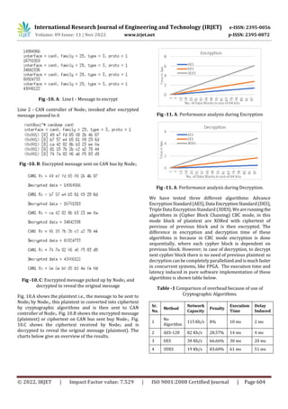
In Table 1, entry 1 shows the actual network load achieved
without use of any cryptographic algorithm. AES being the
fastest uses more computation power, followed by DES and
then 3DES. These implementedalgorithmscauseanincrease
in network load because of the limited data size of standard
CAN frame which is overcome by sending multiple CAN
frames for one message. This may not be a problem for low
traffic networks however with the advancement in modern
vehicles there is more integration of sophisticated
technology (Ex: ADAS) the number of ECUs are only goingto
go up. Hence, it is imperative to look for a solution that
satisfies the time-critical needs of CAN bus communication.
4. PRACTICAL IMPLICATIONS
The test-bed can be used to evaluate different proposed
security measures and carry out analysis for areas of
improvement. We have demonstrated test-bed’s
functionality and analysedtheperformanceofcryptographic
algorithms in CAN communication. This test-bed is a
versatile option that facilitates fast paced development and
deployment. Application program can be developedinother
system and then can be directly copied into the memory of
the test-bed. For any fine tuning or changes needed in
program, it can be done directly by accessing the program
through the Linux shell in test-bed. This is helpful when
iterative changes are made to program. The system does not
need to restart every time, all the changes can be made
directly to program while the test-bed is online. Moreover,
this system gives the ability to debug a program which isnot
possible when bare-metal application is created, the error
handling and prompting ability is just another advantage of
this test-bed. This test-bed is intended for evaluation and
development of security measures. Once a satisfactory
analysis is carried out, later a bare-metal application or
RTOS (Real Time Operating System) based solution can be
developed to improve execution speed.
5. CONCLUSION & FUTURE SCOPE
The functionality and viability of the test-bed has been
verified through different experiments. The test-bed is
simple, stable and practical, and thus can be used for further
studies and evaluations. Hardware-based solutions are
better when it comes to performance and security, but are
not versatile. Software based solutions are versatile but
effective only whenhighperformanceCPUsareavailableand
they induce communication delay. Taking advantage of high
level of parallelism offered by FPGA and flexibility of
Embedded Systems it is possibletocomewitha versatile and
high-performance security solutions. Based on the findings
of subsequent tests, the primary goal would be to
concentrate on creatinga workablesolutionforsafeguarding
CAN Bus communications.
REFERENCES
[1] OpenCores SJA1000 controller. Available at:
https://canbus.pages.fel.cvut.cz/
[2] Koscher, Karl, et al. "Experimental security analysis of a
modern automobile." 2010 IEEE Symposium on Security and
Privacy. IEEE Computer Society, 2010.
[3] Bozdal, Mehmet, et al. "Evaluation of can bus security
challenges." Sensors 20.8 (2020): 2364
[4] Lin, Chung-Wei, and Alberto Sangiovanni-Vincentelli.
"Cyber-security for the controller area network (CAN)
communication protocol." 2012 International Conference on
Cyber Security. IEEE, 2012.
[5] Szilagy, Chris, and Philip Koopman. "A flexible approach
to embedded network multicast authentication." (2008).
[6] Huang, Tianxiang, et al. " ATG: An Attack Traffic
Generation Tool for Security Testing of In-vehicle CAN
Bus"(2018)
[7] Payne, Bryson R. (2019) "Car Hacking: Accessing and
Exploiting the CAN Bus Protocol," Journal of Cybersecurity
Education, Research and Practice: Vol. 2019 : No. 1 , Article 5
[8] K. Koscher et al., ``Experimental security analysis of a
modern automobile,''in Proc. IEEE Symp. Secur. Privacy,
Oakland, CA, USA, May 2010,pp. 447_462.
[9] (2014). The Lockheed Martin Cyber Kill Chain. [Online].
Available
:http://cyber.lockheedmartin.com/hubfs/Gaining_the_Adva
ntage_Cyber_Kill_Chain.pdf
[10] H. Gustavsson and J. Axelsson, ``Evaluating _exibility in
embedded automotive product lines using real options,'' in
Proc. 12th Int. Softw. Product Line Conf., Sep. 2008, pp.
235_242.
[12] K. Koscher et al., ``Experimental security analysis of a
modern automobile,'' in Proc. IEEE Symp. Secur. Privacy,
Oakland, CA, USA, May 2010, pp. 447_462.
[13] S. Woo, H. J. Jo, and D. H. Lee, ``A practical wireless
attack on the connected car and security protocol for in-
vehicle CAN,'' IEEE Trans. Intell. Transp. Syst., vol. 16, no. 2,
pp. 993_1006, Apr. 2015.
[14] J. Schmandt, A. T. Sherman,andN.Banerjee,``Mini-MAC:
Raising the bar for vehicular security with a lightweight
message authentication protocol,'' Veh. Commun., vol. 9, pp.
188_196, Jul. 2017.
[15] H. Abdulmalik and B. Luo, ``Using ID-hopping to defend
against targeted DoS on CAN,'' in Proc. 1st Int. WorkshopSafe
Control Connected Auton. Vehicles, 2017, pp. 19_26.](https://image.slidesharecdn.com/irjet-v9i1188-221208094852-e13e189b/85/Implementation-of-CAN-on-FPGA-for-Security-Evaluation-Purpose-6-320.jpg)
![International Research Journal of Engineering and Technology (IRJET) e-ISSN: 2395-0056
Volume: 09 Issue: 11 | Nov 2022 www.irjet.net p-ISSN: 2395-0072
© 2022, IRJET | Impact Factor value: 7.529 | ISO 9001:2008 Certified Journal | Page 606
[16] L. Martin, P. Mundhenk, and S. Steinhorst, ``Security-
aware obfuscated priority assignment for automotive CAN
platforms,'' ACM Trans. Des Automat. Electron. Syst., vol. 21,
no. 2, pp. 1_27, 2016.
[17] P.-S. Murvay and B. Groza, ``DoS attacks on controller
area networks by fault injectionsfromthesoftwarelayer,'' in
Proc. 12th Int. Conf.Availability, Rel. Secur., 2017, p. 71.
[19] Guido Bertoni, Joan Daemen, Michael Peeters,andGilles
Van Assche. Keccak Specifications, 2009.
[18] S. Woo, D. Moon, T. -Y. Youn, Y. Lee and Y. Kim, "CAN ID
Shuffling Technique (CIST): Moving Target DefenseStrategy
for Protecting In-Vehicle CAN," in IEEE Access, vol. 7, pp.
15521-15536, 2019, doi: 10.1109/ACCESS.2019.2892961.
[20] Bellare, M., Rogaway, P. (1994). Entity Authentication
and Key Distribution. In: Stinson, D.R. (eds) Advances in
Cryptology — CRYPTO’ 93. CRYPTO 1993. Lecture Notes in
Computer Science, vol 773. Springer, Berlin, Heidelberg.
https://doi.org/10.1007/3-540-48329-2_21
[21] Elinux.org. Available at:
https://elinux.org/index.php?title=Python_Can&action=edit
[22] Digilent, Inc. Available at:
https://digilent.com/reference/programmable-
logic/zybo/start](https://image.slidesharecdn.com/irjet-v9i1188-221208094852-e13e189b/85/Implementation-of-CAN-on-FPGA-for-Security-Evaluation-Purpose-7-320.jpg)

This document describes the implementation of a Controller Area Network (CAN) bus on an FPGA for the purpose of evaluating security measures. It discusses how implementing CAN on an FPGA-based testbed allows for faster development and evaluation of cryptographic algorithms and other security primitives for securing CAN communications compared to using a real vehicle. The testbed design uses a Xilinx Zynq SoC with a modified OpenCores SJA1000 CAN controller in the programmable logic interfaced to a CAN transceiver. A Linux system is built on the processing system for application development and interfacing with the CAN controller to test security measures for the CAN bus.


