More Related Content
Similar to Ijetcas14 615 (20)
Ijetcas14 615
- 1. International Association of Scientific Innovation and Research (IASIR)
(An Association Unifying the Sciences, Engineering, and Applied Research)
(An Association Unifying the Sciences, Engineering, and Applied Research)
International Journal of Emerging Technologies in Computational
and Applied Sciences (IJETCAS)
www.iasir.net
IJETCAS 14- 615; © 2014, IJETCAS All Rights Reserved Page 276
ISSN (Print): 2279-0047
ISSN (Online): 2279-0055
A Review on Bandwidth Enhancement Methods of Microstrip Patch
Antenna
Tanvir Singh Buttar1
, Narinder Sharma2
1
M.Tech. Scholar, Department of ECE, AICTE, PTU, Amritsar College of Engg. & Tech., Amritsar-
Jalandhar GT road, Manawala, Amritsar, India, tanvirbuttar88@gmail.com
2
Associate Professor, Department of EEE, AICTE, PTU, Amritsar College of Engg. & Tech., Amritsar-
Jalandhar GT road, Manawala, Amritsar, India, narinder.acet@gmail.com
Abstract: Microstrip patch antenna (MPA) plays significant role in modern communication devices. And a large
part of daily communication is done by using MPA. The study of MPA has made great progress in recent years.
The study of literature work shows that the major work is concentrated on designing small sized broadband
MPA. As the antennas are build smaller, the operating bandwidth decreases. Hence to improve bandwidth
different techniques are used. This review paper delivers various bandwidth enhancement techniques since last
few years.
Keywords: Microstrip patch antenna (MPA), Bandwidth enhancement, Dielectric constant, Antenna design,
substrate.
I. Introduction
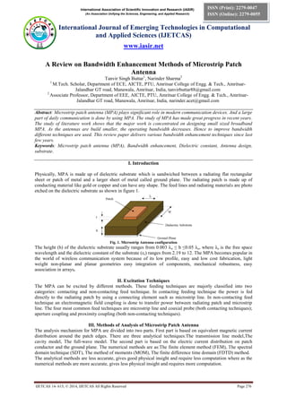
Physically, MPA is made up of dielectric substrate which is sandwiched between a radiating flat rectangular
sheet or patch of metal and a larger sheet of metal called ground plane. The radiating patch is made up of
conducting material like gold or copper and can have any shape. The feed lines and radiating materials are photo
etched on the dielectric substrate as shown in figure 1.
Fig. 1. Microstrip Antenna configuration
The height (h) of the dielectric substrate usually ranges from 0.003 λo ≤ h ≤0.05 λo, where λo is the free space
wavelength and the dielectric constant of the substrate (εr) ranges from 2.19 to 12. The MPA becomes popular in
the world of wireless communication system because of its low profile, easy and low cost fabrication, light
weight non-planar and planar geometries easy integration of components, mechanical robustness, easy
association in arrays.
II. Excitation Techniques
The MPA can be excited by different methods. These feeding techniques are majorly classified into two
categories: contacting and non-contacting feed technique. In contacting feeding technique the power is fed
directly to the radiating patch by using a connecting element such as microstrip line. In non-contacting feed
technique an electromagnetic field coupling is done to transfer power between radiating patch and microstrip
line. The four most common feed techniques are microstrip line and coaxial probe (both contacting techniques);
aperture coupling and proximity coupling (both non-contacting techniques).
III. Methods of Analysis of Microstrip Patch Antenna
The analysis mechanism for MPA are divided into two parts. First part is based on equivalent magnetic current
distribution around the patch edges. There are three analytical techniques:The transmission line model,The
cavity model, The full-wave model. The second part is based on the electric current distribution on patch
conductor and the ground plane. The numerical methods are as:The finite element method (FEM), The spectral
domain technique (SDT), The method of moments (MOM), The finite difference time domain (FDTD) method.
The analytical methods are less accurate, gives good physical insight and require less computation where as the
numerical methods are more accurate, gives less physical insight and requires more computation.
- 2. Tanvir S. Buttaret al., International Journal of Emerging Technologies in Computational and Applied Sciences, 9(3), June-August, 2014,
pp. 276-279
IJETCAS 14- 615; © 2014, IJETCAS All Rights Reserved Page 277
IV. Need of Higher Bandwidth
Generally, the MPA has a narrow bandwidth besides that today wireless communication system demands higher
operating bandwidth. These communication devices need higher bandwidth so as to work in the broader band in
order to shoulder high speed internet, multimedia communication like 9.5% for a digital communication system
(1710-1880 MHz), 12% for universal mobile telecommunication system (1920-2170 MHz), 7% for global
system for mobile communication (890-960)[1]. In order to fulfil the demands of the bandwidth various
techniques are employed and some of them are described in this review paper.
V. Literature Survey
The concept of MPA revert back about 26 years to work by Deschamps in USA[2], by Gutton and Baissinot in
France[3]. Afterwards Lewin explored radiation from stripline discontinuities. Further studies were assumed in
1960 by kaloi, who considered the rectangular and square configurations. But the report of Deschamps work
was not announced until the 1970’s, when the conducting strip radiator ( half wavelength wide and a few
wavelengths long fed by coaxial connections) separated by a dielectric substrate from a ground plane was
explained by Byron. This concept was used in Project Camel. After that, the microstrip element was manifested
by Munson[4] and data on circular and rectangular microstrip patched was reported by Howell. Weinschel
evolved various microstrip geometries for use with cylindrical S band arrays on rockets. Further work on basic
microstrip patch elements was announced in 1975 by Garvin et al, Weinschel, Janes, Howell and Wilson. The
development of microstrip antennas by Munson, for use as low profile flush mounted antennas on missiles and
rockets reveals that this was a practical concept which can be used in solving various antenna problems and
hence invented the new antenna industry.
Parminder singh et. al [5], highlighted the bandwidth enhancement of probe fed MPA. Chen and Zhang [6]
explained the bandwidth enhancement of a microstrip of a microstrip-linefed printed wide slot antenna with a
fractal shaped slot. Shubam Gupta et al[7], described the bandwidth enhancement in multi patch microstrip
antenna array. M. Gujral et al[8], introduces the bandwidth improvement of microstrip antenna array using
dummy EBG pattern on feed line. Song and Zhang [9], desigend a novel momopole antenna with a self similar
slot for wideband applications. R.C Hadarig M.E. de Cos and F. Las-Heras [10], have presented microstrip
patch antenna with enhanced bandwidth using AMC/EBG structures. Sandeep Kumar et. Al[11], proposed a
design of microstrip square shaped patch antenna for improvement of bandwidth and directivity gain. Parmar,
and Makwana [12], introduces the bandwidth enhancement of microstrip patch antenna using parasitic patch
configuration. Jia-Yi Sze and Kin-Lu Wong [13], shows the slotted rectangular microstrip antenna for
bandwidth enhancement. Qu, D. ; Shafai, L. ; Foroozesh, A. [14], highlights the Improvement of microstrip
patch antenna performance using EBG substrates. D. C. Chang, J. X. Zheng [15], describes the Wide-Band
microstrip antenna using two triangular patches. Parminder singh, Anjali Chandel, Divya Naina[16], explains
the bandwidth enhancement of probe fed microstrip patch antenna. Juhua Liu, Quan Xue, HangWong, Hau Wah
Lai, and Yunliang Long [17], describes thedesign and analysis of a low- profile and broadband microstrip
monopolar patch antenna. Y. Sung [18], introduces the bandwidth enhancement of a microstrip line-fed printed
wide-slot antenna with a parasitic center patch. Aliakbar Dastranj and Habibollah Abiri [19], highlights the
bandwidth enhancement of printed e-shaped slot antennas fed by cpw and microstrip line.
VI. Techniques To Enhance Bandwidth Of Microstrip Patch Antenna
The techniques used to uplift the bandwidth of the microstrip patch antenna are described below.
A. Broadband Mcrostrip Patch Antennas Having Modified Patch Shapes
Bandwidth is enhanced by using this technique by simply modifying i.e changing the radiating patch’s shape. In
other words by changing the shape of rectangular and circular patches into rectangular ring and circular ring so
as to enhance the Bandwidth. By modifying the shapes of the patches the bandwidth improves because the
quality factor reduces, as the less energy will be stored under the patch and produces higher radiation.
B. Broadband Mcrostrip Patch Antennas Having Multilayer Configuration
The patches are planted over the various dielectric substrates and are stacked on each other, in case of multilayer
configuration. The coupling in the multilayer configuration can be done in two ways either by electromagnetic
coupling or aperture coupling.. Ground plane have an aperture slot in aperture coupling and to avoid the
radiation losses the substrate is made up of high dielectric constant and the top patch is made up of thick
dielectric substrate with low dielectric constant. In electromagnetic coupled MPA one or more patches are
placed over different dielectric layers. In two layered configuration then any one of them is fed and other is
electromagnetically coupled.
- 3. Tanvir S. Buttaret al., International Journal of Emerging Technologies in Computational and Applied Sciences, 9(3), June-August, 2014,
pp. 276-279
IJETCAS 14- 615; © 2014, IJETCAS All Rights Reserved Page 278
Although the dielectric constant and dimension of the patch may varies but the resonant frequency is near to
each other in order to have high bandwidth [20]. Broad bandwidth approximately 70% can be obtained by
making use of multilayer configuration.
C. Broadband Microstrip Patch Antenna Having Planar Multiresonator Configuration
In the planar multi-resonator configuration the multiple resonators are placed close to each other and only one is
fed and others are parasitically coupled also called as gap coupled. This configuration can also be fed by directly
connecting the patches through microstrip line. In certain cases both direct and gap coupling is used and is
called as hybrid coupling. The major disadvantages of this configuration is that these configuration is not
suitable for an array configuration, as their size is too large and there is changes in the radiation pattern over the
impedance matching.
D. Broadband Microstrip Patch Antenna Having Stacked Multiresonator Configuration
This configuration is evolved by the combination of stacked configuration and multi-resonator configuration in
order to further enhance the bandwidth. Although the size of the stacked multi-resonator microstrp patch
antenna is not small but it provides very high bandwidth and gain.
Table1: Comparison of different broadband techniques
S. No. Broadband Techniques Configuration Remarks
1. Modified patch shapes
T-slot rectangular patch[21] Impedance Bandwidth of 25.23% with average
gain of 7.43 dBi is obtained.
E-H shaped patch[22] Delivered bandwidth is about 27%
U-shaped slot with single-layer
single- patch[23]
Air substrate of 12 mm is used to provide
bandwidth of 27.5%.
2. Multilayered Technique
Multilayered configuration of
patches[24]
Nearly 70% of bandwidth can be otained by
making use of multilayered configuration of
radiating patches
3. Multi resonator Technique
Gap-coupled multi resonator and
stacked configuration[25]
delivers bandwidth of 25.7% with more than 10
dB gain.
Shifted parasitically coupled
multiresonator[26]
Improves the impedance bandwidth from 65
MHz to 251 MHz
Directly coupled and parasitic
patches[27]
Impedance bandwidth of 12.7% (365 MHz) is
yeilded, which is 6.35 times when compared
with the simple patch i.e. 2% (54 MHz) at same
center frequency of 2879 MHz
4. Stacked Multilayered
Technique
Gap-coupled planar multiresonator
and stacked configuration[25]
bandwidth of 25.7% with more than 10 dB gain
Stacked U-slot microstrip antenna
incorporating E-shape and
modified half-E shape radiating
patch configuration[28]
Maximum impedance bandwidth of 60.2% can
be obtained
E. Impact of Varrious Feeding Techniques on Bandwidth of Microstrip Patch Antenna.
There are variety of feeding techniques which can be used to feed the microstrip patch antenna. Feeding
techniques are broadly categorised into two categories: contact feeding and non-contact feeding. These
techniques are mentioned above in this paper. A better impedance matching between a patch and the feed line
without using any extra matching element depends on the type of feeding technique used. As shown in table the
proximity coupled feed technique provides the highest bandwidth.
Table 2: Comparison of Feeding Techniques
Characteristics Microstrip Line Feed Coaxial Feed Aperture Coupled Feed Proximity Coupled
Feed
Bandwidth 2-5% 2-5% 2-5% 13%
VII. CONCLUSION
Low bandwidth is always the limitation of MPA. The impact of different broadband microstrip patch antenna
configurations and feeding techniques on the bandwidth of the microstrip patch antenna has been presented in
this paper so as to increase the operating bandwidth. After an exhaustive study of literature work it is perceived
that in case of feeding techniques, the proximity coupled feeding technique delivers the maximal bandwidth.
And among all techniques multilayer structures provide maximum bandwidth but its size increases with the
increase in number of layers. Slot loaded techniques can be used to further enhance the bandwidth as they have
inherent advantage that the size of the antenna remains small.
- 4. Tanvir S. Buttaret al., International Journal of Emerging Technologies in Computational and Applied Sciences, 9(3), June-August, 2014,
pp. 276-279
IJETCAS 14- 615; © 2014, IJETCAS All Rights Reserved Page 279
REFERENCES
[1] Kin-Lu Wong, “Compact and Broadband Microstrip Antennas”, John Wiley & Sons, page number: 12-14, ISBNs: 0-471-41717-
3, 2002.
[2] G. A.Deschamps, “Microstrip microwave antennas”, presented at the 3rd USAF Symp. On antennas, 1953.
[3] H. Gutton and G. Baissinot, “Flat aerial for ultra high frequencies”, French patent No. 703113, 1955
[4] R. E. Munson, “Single slot cavity antennas assembly”, U.S. patent No. 3713 162, January 23, 1973.
[5] Parminder singh et. Al,” bandwidth enhancement of probe fed MPA” International journal of electronics communication and
computer technology (IJECCT), Vol. 3, No. 1, pp. 368-371, 1992.
[6] Chen, W. L., G. M. Wang, and C. X. Zhang, “Bandwidth enhancement of a microstrip-linefed printed wideslot antenna with a
fractalshaped slot” IEEE Transactions on Antennas Propagation, Vol. 57, No. 7, 2176-2179,2009.
[7] Shubam Gupta et al, “bandwidth enhancement in multi patch microstrip antenna array”, International Journal of Application or
Innovation in Engineering and Technology (IJAIEM), Vol. 2, No. 2, pp. 353-358, 2013.
[8] M. Gujral et al, “ bandwidth improvement of microstrip antenna array using dummy EBG pattern on feed line”, Progress in
electromagnetic research Symposium (PIERS) Proceedings, Vol. 127, pp. 79-92, 2012.
[9] Kim, H. and C.-W. Jung, “Bandwidth enhancement of CPW fed tapered slot antenna with multitransformation characteristics”
Electronics Letters, Vol. 46, No. 15, pp.1050-1051, 2010.
[10] ] R.C Hadarig M.E. de Cos and F. Las-Heras, “microstrip patch antenna with enhanced bandwidth using AMC/EBG structures”,
Hindawi Publishing Corporation International Journal of Antennas and Propogation, Article ID 843754, 6 pages, 2012.
[11] Sandeep Kumar et. Al, “design of microstrip square shaped patch antenna for improvement of bandwidth and directivity gain”,
International Journal of Engineering Research a and Applications (IJERA), Vol. 2, no. 2, pp. 441-444, 2012.
[12] Parmar, and Makwana ,“Bandwidth Enhancement of Microstrip Patch Antenna Using Parasitic Patch Configuration” IEEE
conference published in Communication Systems and Network Technologies (CSNT), Rajkot,pp. 53 - 57 ,11-13 May 2012
[13] Jia-Yi Sze and Kin-Lu Wong, “Slotted rectangular microstrip antenna for bandwidth enhancement” IEEE Transactions on
Antennas and Propagation, vol. 48 , issue no. 8, pp. 1149 – 1152, Aug 2000.
[14] Qu, D. ; Shafai, L. ; Foroozesh, A. , “Improving microstrip patch antenna performance using EBG substrates” IEE Proc.
Microwave Antennas Propag., Vol. 153, Issue No. 6, pp. 558-563, December 2006.
[15] D. C. Chang, J. X. Zheng, "A Wide-Band microstrip antenna using two triangular patches", IEEE Tran. Antennas Propagation,
vol. 51, Issue No. 9, pp. 2218-2216, Sept 2003.
[16] Parminder singh, Anjali Chandel, Divya Naina, “Bandwidth Enhancement of Probe Fed Microstrip Patch Antenna,”,
International Journal of Electronics Communication and Computer Technology (IJECCT), Volume 3, Issue No. 1, pp. 368-371,
January 2013.
[17] Juhua Liu, Quan Xue, HangWong, Hau Wah Lai, and Yunliang Long, “Design and Analysis of a Low- Profile and Broadband
Microstrip Monopolar Patch Antenna,” IEEE Transactions on Antennas and Propagation, VOL. 61, NO. 1, pp. 11-18, Jan. 2013.
[18] Y. Sung, “Bandwidth Enhancement of a Microstrip Line-Fed Printed Wide-Slot Antenna With a Parasitic Center Patch,” IEEE
Transactions on Antennas and Propagation, VOL. 60, NO. 4, pp. 1712-1716, Apr. 2012.
[19] Aliakbar Dastranj and Habibollah Abiri, “Bandwidth Enhancement of Printed E-Shaped Slot Antennas Fed by CPW and
Microstrip Line,” IEEE Transactions On Antennas And Propagation,” Vol. 58,No. 4, pp. 1402-1407, 2010.
[20] Girish Kumar and K.P. Ray, “Broadband microstrip antennas”, Artech House antennas and propagation library, page number:
15-17, ISBN 1-58053-244-6, 2003.
[21] Lolit Kumar Singh, Bhaskar Gupta and Partha P. Sarkar, “T-slot Broadband Rectangular Patch Antenna”, International Journal
of Electronic and Electrical Engineering Vol. 4, page number: 43-47, ISSN 0974-2174, 2011.
[22] Mohammad Tariqul Islam, Mohammed Nazmus Shakib and et al., “Modified E-H Shaped Microstrip Antenna for wireless
Systems”, IEEE International Conference on Networking, Proceedings, ISBN 978-1-4244-3492-3, page number: 794-796, Japan,
March 26-29, 2009
[23] T. Huynh and K. F. Lee, “Single-layer single-patch wideband microstrip antenna”, Electron. Lett. 31, page number: 1310–1311,
Aug. 3, 1995
[24] Girish Kumar and K.P. Ray, “Broadband microstrip antennas”, Artech House antennas and propagation library, page number:
132-138, ISBN 1-58053-244-6, 2003
[25] Girish Kumar and K.P. Ray, “Stacked gap-coupled multi-resonator rectangular microstrip antennas”, Antennas and Propagation
Society International Symposium, IEEE Vol. 3, ISBN 0-7803-7070-8, page number: 514 – 517, Aug. 7, 2002.
[26] K. Chattopadhyay, S.K. Parui, S. Das and S.R. Bhadra Chaudhuri, “Bandwidth Enhancement of Microstrip Antennas Using
Shifted Parasitically Coupled Planar Multiresonators”, Applied Electromagnetics Conference(AEMC), IEEE, ISBN 978-1-4244-
4819-7, 2009.
[27] C. K. Wu and K. L. Wong, “Broadband microstrip antenna with directly coupled and gap-coupled parasitic patches”, Microwave
Opt. Technol. Lett. 22, 348–349, Sept. 5, 1999.
[28] M. A. Matin, B. S. Sharif and C. C. Tsimenidis, “Broadband Stacked Microstrip Antennas with Different Radiating Patch”,
Springer Science Business Media- Wireless Pers Commun, page number: 637-648, 11277-009-9836-7, Oct. 9, 2009.
![Tanvir S. Buttaret al., International Journal of Emerging Technologies in Computational and Applied Sciences, 9(3), June-August, 2014,
pp. 276-279
IJETCAS 14- 615; © 2014, IJETCAS All Rights Reserved Page 277
IV. Need of Higher Bandwidth
Generally, the MPA has a narrow bandwidth besides that today wireless communication system demands higher
operating bandwidth. These communication devices need higher bandwidth so as to work in the broader band in
order to shoulder high speed internet, multimedia communication like 9.5% for a digital communication system
(1710-1880 MHz), 12% for universal mobile telecommunication system (1920-2170 MHz), 7% for global
system for mobile communication (890-960)[1]. In order to fulfil the demands of the bandwidth various
techniques are employed and some of them are described in this review paper.
V. Literature Survey
The concept of MPA revert back about 26 years to work by Deschamps in USA[2], by Gutton and Baissinot in
France[3]. Afterwards Lewin explored radiation from stripline discontinuities. Further studies were assumed in
1960 by kaloi, who considered the rectangular and square configurations. But the report of Deschamps work
was not announced until the 1970’s, when the conducting strip radiator ( half wavelength wide and a few
wavelengths long fed by coaxial connections) separated by a dielectric substrate from a ground plane was
explained by Byron. This concept was used in Project Camel. After that, the microstrip element was manifested
by Munson[4] and data on circular and rectangular microstrip patched was reported by Howell. Weinschel
evolved various microstrip geometries for use with cylindrical S band arrays on rockets. Further work on basic
microstrip patch elements was announced in 1975 by Garvin et al, Weinschel, Janes, Howell and Wilson. The
development of microstrip antennas by Munson, for use as low profile flush mounted antennas on missiles and
rockets reveals that this was a practical concept which can be used in solving various antenna problems and
hence invented the new antenna industry.
Parminder singh et. al [5], highlighted the bandwidth enhancement of probe fed MPA. Chen and Zhang [6]
explained the bandwidth enhancement of a microstrip of a microstrip-linefed printed wide slot antenna with a
fractal shaped slot. Shubam Gupta et al[7], described the bandwidth enhancement in multi patch microstrip
antenna array. M. Gujral et al[8], introduces the bandwidth improvement of microstrip antenna array using
dummy EBG pattern on feed line. Song and Zhang [9], desigend a novel momopole antenna with a self similar
slot for wideband applications. R.C Hadarig M.E. de Cos and F. Las-Heras [10], have presented microstrip
patch antenna with enhanced bandwidth using AMC/EBG structures. Sandeep Kumar et. Al[11], proposed a
design of microstrip square shaped patch antenna for improvement of bandwidth and directivity gain. Parmar,
and Makwana [12], introduces the bandwidth enhancement of microstrip patch antenna using parasitic patch
configuration. Jia-Yi Sze and Kin-Lu Wong [13], shows the slotted rectangular microstrip antenna for
bandwidth enhancement. Qu, D. ; Shafai, L. ; Foroozesh, A. [14], highlights the Improvement of microstrip
patch antenna performance using EBG substrates. D. C. Chang, J. X. Zheng [15], describes the Wide-Band
microstrip antenna using two triangular patches. Parminder singh, Anjali Chandel, Divya Naina[16], explains
the bandwidth enhancement of probe fed microstrip patch antenna. Juhua Liu, Quan Xue, HangWong, Hau Wah
Lai, and Yunliang Long [17], describes thedesign and analysis of a low- profile and broadband microstrip
monopolar patch antenna. Y. Sung [18], introduces the bandwidth enhancement of a microstrip line-fed printed
wide-slot antenna with a parasitic center patch. Aliakbar Dastranj and Habibollah Abiri [19], highlights the
bandwidth enhancement of printed e-shaped slot antennas fed by cpw and microstrip line.
VI. Techniques To Enhance Bandwidth Of Microstrip Patch Antenna
The techniques used to uplift the bandwidth of the microstrip patch antenna are described below.
A. Broadband Mcrostrip Patch Antennas Having Modified Patch Shapes
Bandwidth is enhanced by using this technique by simply modifying i.e changing the radiating patch’s shape. In
other words by changing the shape of rectangular and circular patches into rectangular ring and circular ring so
as to enhance the Bandwidth. By modifying the shapes of the patches the bandwidth improves because the
quality factor reduces, as the less energy will be stored under the patch and produces higher radiation.
B. Broadband Mcrostrip Patch Antennas Having Multilayer Configuration
The patches are planted over the various dielectric substrates and are stacked on each other, in case of multilayer
configuration. The coupling in the multilayer configuration can be done in two ways either by electromagnetic
coupling or aperture coupling.. Ground plane have an aperture slot in aperture coupling and to avoid the
radiation losses the substrate is made up of high dielectric constant and the top patch is made up of thick
dielectric substrate with low dielectric constant. In electromagnetic coupled MPA one or more patches are
placed over different dielectric layers. In two layered configuration then any one of them is fed and other is
electromagnetically coupled.](data:image/gif;base64,R0lGODlhAQABAIAAAAAAAP///yH5BAEAAAAALAAAAAABAAEAAAIBRAA7)