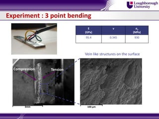
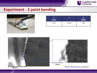
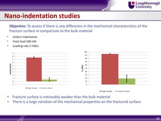
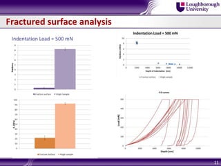
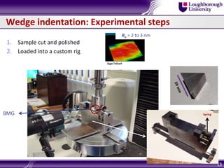
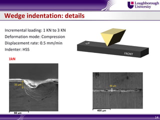
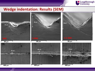
VAHID NEKOUIE
GAYAN ABEYGUNAWARDANE-ARACHCHIGE
ANISH ROY
VADIM SILBERSCHMIDT
1
Mechanics of Advanced
Materials Research Group
What is a Bulk Metallic Glass?
2
• amorphous material: atoms “frozen” in non-crystalline form
• first formed in 1957 by Duwez by rapid quenching
 gold-silicon alloy
 only very thin, small samples could be produced (order or micrometers)
• first believed atoms were randomly packed together densely like hard spheres
in a liquid
 solvent atoms randomly arranged with solute atoms fitting into open cavities
• now believe short-range, even medium-range order exists in materials
Sheng et al. (2006), Nature
What is a Bulk Metallic Glass?
3
BMG
Compared to metals in general, BMGs
have high strength, f and low
stiffness, E
Unusually high Elastic Strain, f/E
From: Material selection in mechanical design, MF Ashby (1999)
Very high Elastic stored energy
Applications
4
Digital light processor, hinges
made of Ti-Al metallic glass with
no fatigue failure after 1012 cycles.
Micro components in
MEMS devices
LENGTH SCALES
Introduction & Motivation
 Deformation mechanisms of metallic glass are unique
 plastic shear flow in the micro scale, but brittle fracture in macro scale
 At ambient temperatures/high stress: flow localization in shear bands (SB)
 At high temperatures/low stress: homogeneous viscous flow
Research Objectives
 Experiments: study SB initiation and evolution under loads. Characterise SBs
mechanically.
 Modelling: Develop a continuum model of SB initiation and propagation,
which can then be used to study component deformations across length
scales
5
What is a Shear band?
 Localised thin bands (~ 10 - 20 nm).
 Cohesion is maintained across the planes.
 Propagation is inhomogeneous
 Propagation depends on loading conditions, sample imperfection.
 Origin of SB is controversial: structural change? Temperature rise? Localised melting?
6
Source – nature materials
BMG alloy and experiments
BMG alloy manufactured at IFW/Dresden
Zr48Cu36Al8Ag8
Samples: 70 mm × 10 mm × 2 mm ; 40 mm × 30 mm × 1.5 mm
7
Characterisation (is it actually amorphous?)
X-ray diffraction (XRD)
No obvious presence of
crystalline phases
Experiment : 3 point bending
E
(GPa)
ν σy
(MPa)
95.4 0.345 930
3mm
TensionCompression
100 µm
Vein like structures on the surface
Experiment : 3 point bending
E
(GPa)
ν σy
(MPa)
95.4 0.345 930
400 µm
10 µm
Shear Bands are evident
Nano-indentation studies
10
• Fracture surface is noticeably weaker than the bulk material
• There is a large variation of the mechanical properties on the fractured surface
Objective: To assess if there is any difference in the mechanical characteristics of the
fracture surface in comparison to the bulk material
 Vickers indentation
 Total load 100 mN
 Loading rate 2 mN/s
Fractured surface analysis
11
Indentation Load = 500 mN
Wedge indentation studies
Why wedge?
Observing shear bands in Nano/Microindentation is difficult
o Shear bands initial in the material volume
o Bonded interface method is not ideal
With a Wedge we have a 2D plane-strain scenario
 Observe shear bands terminating on the surface as they initiation and evolve.
 Relatively easy to setup
 Easy to model
12
1. Sample cut and polished
2. Loaded into a custom rig
Wedge indentation: Experimental steps
13
Zygo Talisurf
Ra = 2 to 3 nm
BMG Spring
Wedge indentation: details
Incremental loading: 1 KN to 3 KN
Deformation mode: Compression
Displacement rate: 0.5 mm/min
Indenter: HSS
14
60 µm
1kN
22 m
400 µm
50 m
Wedge indentation: Results (SEM)
60 µm
1kN
22 m
1-2kN
60 µm
50 m
1-2-3kN
60 µm
85m
400 µm 400 µm 400 µm
85 m 130m
50 m
Wedge indentation: Load-Displacement Curve
Single load, different locations
Incremental load, same location
~ 50µm
~22 µm
Area under the curve will give us work done for plastic deformation
Shear Bands: XRD results
17
XRD results are inconclusive since crystalline phases < 5% is hard to detect
Shear Band analysis/ TEM + SAED
18
Virgin Sample Shear Band
Crystalline material
FIB
milling
TEM/SAED sample
Shear Bands are fully
amorphous
Nano-indentation studies on a Shear Band
 Vickers indentation
 Total load 100 mN
 Loading rate 2 mN/s
19
Nano-indentation studies on a Shear Band
20
MODELLING OF WEDGE INDENTATION
/Finite Element Modelling
21
Microscale modelling – Bulk material
 Drucker – Prager : hydrostatic stress component is considered.
 Captures the rise of shear strength with the increase of hydrostatic pressure
increase. – Major cause for adoption.
𝐹 = 𝐽2 − 𝜃𝐼1 − 𝑘
J2 – second deviatoric stress invariant 𝜃 – constant for a given material
I1 – first stress invariant 𝑘 – hardening and softening function
ABAQUS 6.12 is used to model
Linear Drucker - Prager criterion is used:
𝒇 = 𝒕 − 𝒑𝒕𝒂𝒏𝜷 − 𝒅 Here: 𝜷 = 𝒇𝒓𝒊𝒄𝒕𝒊𝒐𝒏 𝒂𝒏𝒈𝒍𝒆 and 𝒅 = 𝒄𝒐𝒉𝒆𝒔𝒊𝒐𝒏 𝒑𝒂𝒓𝒂𝒎𝒆𝒕𝒆𝒓
To calculate, 𝒕 and 𝒅: 𝑡 =
1
2
q 1 +
1
𝑘
− 1 −
1
𝑘
𝑟
𝑞
3
and 𝑑 = 1 −
1
3
𝑡𝑎𝑛𝛽 𝜎𝑐
𝑞 = 𝑣𝑜𝑛 𝑚𝑖𝑠𝑒𝑠 𝑒𝑞𝑢𝑖𝑣𝑎𝑙𝑎𝑛𝑡 𝑠𝑡𝑟𝑒𝑠𝑠, 𝑘 = 𝑟𝑎𝑡𝑖𝑜 𝑜𝑓 𝑦𝑖𝑒𝑙𝑑 𝑠𝑡𝑟𝑒𝑠𝑠 𝑖𝑛 𝑡𝑟𝑖𝑎𝑥𝑖𝑎𝑙 𝑠𝑡𝑎𝑡𝑒
𝑟 = 𝑡ℎ𝑖𝑟𝑑 𝑖𝑛𝑣𝑎𝑟𝑖𝑎𝑛𝑡 𝑜𝑓 𝑡ℎ𝑒 𝑑𝑒𝑣𝑖𝑎𝑡𝑜𝑟𝑖𝑐 𝑠𝑡𝑟𝑒𝑠𝑠
22
Microscale modelling – Shear band
 Cohesive Zone Elements with traction separation law.
 Shear band thickness lies in the ~nm scale. This fact prompt to employ
traction separation laws.
23
Linear elastic behaviour
𝜀 𝑛 =
𝛿 𝑛
𝑇0
, 𝜀 𝑠 =
𝛿 𝑠
𝑇0
, 𝜀𝑡 =
𝛿 𝑡
𝑇0
Traction – Separation response
Damage initiation criterion
𝜀 𝑛
𝜀 𝑛
0
2
+
𝜀 𝑠
𝜀 𝑠
𝑜
2
+
𝜀𝑡
𝜀𝑡
𝑜
2
= 1
Nominator calculated by the solver,
Denominator is user input dependent.
Linear damage evolution
𝐷 =
𝛿 𝑚
𝑓
𝛿 𝑚
𝑚𝑎𝑥−𝛿 𝑚
0
𝛿 𝑚
𝑚𝑎𝑥 𝛿 𝑚
𝑓
−𝛿 𝑚
0
𝛿 𝑚
𝑓
− effective displacement at complete failure,
𝛿 𝑚
0
− effective displacement at damage initiation
𝛿 𝑚
𝑓
− effective traction at damage initiation,
𝛿 𝑚
𝑚𝑎𝑥
− maximum value of the effective displacement
24
• Wedge Indenter Radius: 20 μm
• FE Model Dimension: (2000 × 2000 ) µm
• Element type:
Bulk Specimen and indenter – CPE4R
Shear bands – COH2D4
• Wedge Indenter: Deformable Body
FE model
2D Plain Strain
BC: bottom rigid
25
FE model – Material Properties
Drucker-Prager parameters
Hardening
Angle of
friction(β)
Flow stress
ratio
Dilation angle (ψ)
0.01° 1 0.02°
Shear damage parameters
Yield stress (MPa) Plastic strain
Fracture
strain
Shear stress
ratio
Strain rate ( s-1 )
930 0
0.05 1 0.016
• Material Properties for bulk metallic glass –
E (GPa) ν
95.4 0.345
• Material Properties for deformable indenter (HSS)–
E (GPa) ν
231 0.30
• Material properties for CZE were chosen by sensitivity analysis.
26
FE model: Results
Damage initiation and propagation through the shear band
Outlook & Future Work
 SB and Fracture surface are weaker than bulk material
 SB are amorphous … rules out melting
 Cohesive Zone Elements can be used to determined the
propagation along the shear band.
 A gradient plasticity based approach is currently being developed
to capture the nucleation and the effect of the local shear bands.
27
28
• Wedge Indenter Radius: 21 μm
• FE Model Dimension: (2000 × 2000 ) µm
• Element type:
Bulk Specimen and indenter – CPE4R
Shear bands – COH2D4
• Wedge Indenter: Deformable Body
FE model
2D Plain Strain
BC: bottom rigid

ICAM3D-2014 BMG experiments and modelling -

  • 1.
    VAHID NEKOUIE GAYAN ABEYGUNAWARDANE-ARACHCHIGE ANISHROY VADIM SILBERSCHMIDT 1 Mechanics of Advanced Materials Research Group
  • 2.
    What is aBulk Metallic Glass? 2 • amorphous material: atoms “frozen” in non-crystalline form • first formed in 1957 by Duwez by rapid quenching  gold-silicon alloy  only very thin, small samples could be produced (order or micrometers) • first believed atoms were randomly packed together densely like hard spheres in a liquid  solvent atoms randomly arranged with solute atoms fitting into open cavities • now believe short-range, even medium-range order exists in materials Sheng et al. (2006), Nature
  • 3.
    What is aBulk Metallic Glass? 3 BMG Compared to metals in general, BMGs have high strength, f and low stiffness, E Unusually high Elastic Strain, f/E From: Material selection in mechanical design, MF Ashby (1999) Very high Elastic stored energy
  • 4.
    Applications 4 Digital light processor,hinges made of Ti-Al metallic glass with no fatigue failure after 1012 cycles. Micro components in MEMS devices LENGTH SCALES
  • 5.
    Introduction & Motivation Deformation mechanisms of metallic glass are unique  plastic shear flow in the micro scale, but brittle fracture in macro scale  At ambient temperatures/high stress: flow localization in shear bands (SB)  At high temperatures/low stress: homogeneous viscous flow Research Objectives  Experiments: study SB initiation and evolution under loads. Characterise SBs mechanically.  Modelling: Develop a continuum model of SB initiation and propagation, which can then be used to study component deformations across length scales 5
  • 6.
    What is aShear band?  Localised thin bands (~ 10 - 20 nm).  Cohesion is maintained across the planes.  Propagation is inhomogeneous  Propagation depends on loading conditions, sample imperfection.  Origin of SB is controversial: structural change? Temperature rise? Localised melting? 6 Source – nature materials
  • 7.
    BMG alloy andexperiments BMG alloy manufactured at IFW/Dresden Zr48Cu36Al8Ag8 Samples: 70 mm × 10 mm × 2 mm ; 40 mm × 30 mm × 1.5 mm 7 Characterisation (is it actually amorphous?) X-ray diffraction (XRD) No obvious presence of crystalline phases
  • 8.
    Experiment : 3point bending E (GPa) ν σy (MPa) 95.4 0.345 930 3mm TensionCompression 100 µm Vein like structures on the surface
  • 9.
    Experiment : 3point bending E (GPa) ν σy (MPa) 95.4 0.345 930 400 µm 10 µm Shear Bands are evident
  • 10.
    Nano-indentation studies 10 • Fracturesurface is noticeably weaker than the bulk material • There is a large variation of the mechanical properties on the fractured surface Objective: To assess if there is any difference in the mechanical characteristics of the fracture surface in comparison to the bulk material  Vickers indentation  Total load 100 mN  Loading rate 2 mN/s
  • 11.
  • 12.
    Wedge indentation studies Whywedge? Observing shear bands in Nano/Microindentation is difficult o Shear bands initial in the material volume o Bonded interface method is not ideal With a Wedge we have a 2D plane-strain scenario  Observe shear bands terminating on the surface as they initiation and evolve.  Relatively easy to setup  Easy to model 12
  • 13.
    1. Sample cutand polished 2. Loaded into a custom rig Wedge indentation: Experimental steps 13 Zygo Talisurf Ra = 2 to 3 nm BMG Spring
  • 14.
    Wedge indentation: details Incrementalloading: 1 KN to 3 KN Deformation mode: Compression Displacement rate: 0.5 mm/min Indenter: HSS 14 60 µm 1kN 22 m 400 µm 50 m
  • 15.
    Wedge indentation: Results(SEM) 60 µm 1kN 22 m 1-2kN 60 µm 50 m 1-2-3kN 60 µm 85m 400 µm 400 µm 400 µm 85 m 130m 50 m
  • 16.
    Wedge indentation: Load-DisplacementCurve Single load, different locations Incremental load, same location ~ 50µm ~22 µm Area under the curve will give us work done for plastic deformation
  • 17.
    Shear Bands: XRDresults 17 XRD results are inconclusive since crystalline phases < 5% is hard to detect
  • 18.
    Shear Band analysis/TEM + SAED 18 Virgin Sample Shear Band Crystalline material FIB milling TEM/SAED sample Shear Bands are fully amorphous
  • 19.
    Nano-indentation studies ona Shear Band  Vickers indentation  Total load 100 mN  Loading rate 2 mN/s 19
  • 20.
  • 21.
    MODELLING OF WEDGEINDENTATION /Finite Element Modelling 21
  • 22.
    Microscale modelling –Bulk material  Drucker – Prager : hydrostatic stress component is considered.  Captures the rise of shear strength with the increase of hydrostatic pressure increase. – Major cause for adoption. 𝐹 = 𝐽2 − 𝜃𝐼1 − 𝑘 J2 – second deviatoric stress invariant 𝜃 – constant for a given material I1 – first stress invariant 𝑘 – hardening and softening function ABAQUS 6.12 is used to model Linear Drucker - Prager criterion is used: 𝒇 = 𝒕 − 𝒑𝒕𝒂𝒏𝜷 − 𝒅 Here: 𝜷 = 𝒇𝒓𝒊𝒄𝒕𝒊𝒐𝒏 𝒂𝒏𝒈𝒍𝒆 and 𝒅 = 𝒄𝒐𝒉𝒆𝒔𝒊𝒐𝒏 𝒑𝒂𝒓𝒂𝒎𝒆𝒕𝒆𝒓 To calculate, 𝒕 and 𝒅: 𝑡 = 1 2 q 1 + 1 𝑘 − 1 − 1 𝑘 𝑟 𝑞 3 and 𝑑 = 1 − 1 3 𝑡𝑎𝑛𝛽 𝜎𝑐 𝑞 = 𝑣𝑜𝑛 𝑚𝑖𝑠𝑒𝑠 𝑒𝑞𝑢𝑖𝑣𝑎𝑙𝑎𝑛𝑡 𝑠𝑡𝑟𝑒𝑠𝑠, 𝑘 = 𝑟𝑎𝑡𝑖𝑜 𝑜𝑓 𝑦𝑖𝑒𝑙𝑑 𝑠𝑡𝑟𝑒𝑠𝑠 𝑖𝑛 𝑡𝑟𝑖𝑎𝑥𝑖𝑎𝑙 𝑠𝑡𝑎𝑡𝑒 𝑟 = 𝑡ℎ𝑖𝑟𝑑 𝑖𝑛𝑣𝑎𝑟𝑖𝑎𝑛𝑡 𝑜𝑓 𝑡ℎ𝑒 𝑑𝑒𝑣𝑖𝑎𝑡𝑜𝑟𝑖𝑐 𝑠𝑡𝑟𝑒𝑠𝑠 22
  • 23.
    Microscale modelling –Shear band  Cohesive Zone Elements with traction separation law.  Shear band thickness lies in the ~nm scale. This fact prompt to employ traction separation laws. 23 Linear elastic behaviour 𝜀 𝑛 = 𝛿 𝑛 𝑇0 , 𝜀 𝑠 = 𝛿 𝑠 𝑇0 , 𝜀𝑡 = 𝛿 𝑡 𝑇0 Traction – Separation response Damage initiation criterion 𝜀 𝑛 𝜀 𝑛 0 2 + 𝜀 𝑠 𝜀 𝑠 𝑜 2 + 𝜀𝑡 𝜀𝑡 𝑜 2 = 1 Nominator calculated by the solver, Denominator is user input dependent. Linear damage evolution 𝐷 = 𝛿 𝑚 𝑓 𝛿 𝑚 𝑚𝑎𝑥−𝛿 𝑚 0 𝛿 𝑚 𝑚𝑎𝑥 𝛿 𝑚 𝑓 −𝛿 𝑚 0 𝛿 𝑚 𝑓 − effective displacement at complete failure, 𝛿 𝑚 0 − effective displacement at damage initiation 𝛿 𝑚 𝑓 − effective traction at damage initiation, 𝛿 𝑚 𝑚𝑎𝑥 − maximum value of the effective displacement
  • 24.
    24 • Wedge IndenterRadius: 20 μm • FE Model Dimension: (2000 × 2000 ) µm • Element type: Bulk Specimen and indenter – CPE4R Shear bands – COH2D4 • Wedge Indenter: Deformable Body FE model 2D Plain Strain BC: bottom rigid
  • 25.
    25 FE model –Material Properties Drucker-Prager parameters Hardening Angle of friction(β) Flow stress ratio Dilation angle (ψ) 0.01° 1 0.02° Shear damage parameters Yield stress (MPa) Plastic strain Fracture strain Shear stress ratio Strain rate ( s-1 ) 930 0 0.05 1 0.016 • Material Properties for bulk metallic glass – E (GPa) ν 95.4 0.345 • Material Properties for deformable indenter (HSS)– E (GPa) ν 231 0.30 • Material properties for CZE were chosen by sensitivity analysis.
  • 26.
    26 FE model: Results Damageinitiation and propagation through the shear band
  • 27.
    Outlook & FutureWork  SB and Fracture surface are weaker than bulk material  SB are amorphous … rules out melting  Cohesive Zone Elements can be used to determined the propagation along the shear band.  A gradient plasticity based approach is currently being developed to capture the nucleation and the effect of the local shear bands. 27
  • 28.
    28 • Wedge IndenterRadius: 21 μm • FE Model Dimension: (2000 × 2000 ) µm • Element type: Bulk Specimen and indenter – CPE4R Shear bands – COH2D4 • Wedge Indenter: Deformable Body FE model 2D Plain Strain BC: bottom rigid

Editor's Notes

  • #3 What is metallic glass? Talk about the definition of metallic glass and talk about crystalline structure, fcc, bcc Metallic glass: metallic compound with glass structure.
  • #5 Modern high-tech industries rely heavily on manufacture and synthesis of advanced materials that are stronger than traditional ones and at the same time environmentally sustainable. Demands in the areas of microelectronics, MEMS (micro-electromechanical systems), miniaturised biomedical devices and implants as well as micro-robotics typically require component sizes at micro to meso length scale where ruggedness, shock resistance, bio-compatibility and environmental sustainability are of paramount importance. Bulk metallic glasses (BMGs) are an emerging class of engineering materials with many desirable and unique properties, which are ideally suited for these applications. BMGs have received much scientific and technological attention due to their unique combination of physical, chemical and mechanical properties such as high values of the Young's modulus and elasticity limit, higher fracture toughness . Power devices, magnet devices. Tregilgas, Adv. Mat. Proc (2004):: DLP reference
  • #23 Tau is the effective yield stress in shear, tau_o = shear resistance of BMG (yield stress in PURE SHEAR), alpha: friction co-eff, sig_n: normal stress on shear plane C: cohesion Phi: angle of friction
  • #27 ** note the different legend for the bottom 2 plots