Download to read offline
![[No Brake]
[Brake-Equipped]
Cable joint
connector *1
ME SE Home ME*2
55
44
26
15
81
59
36.5
ø50
ø48
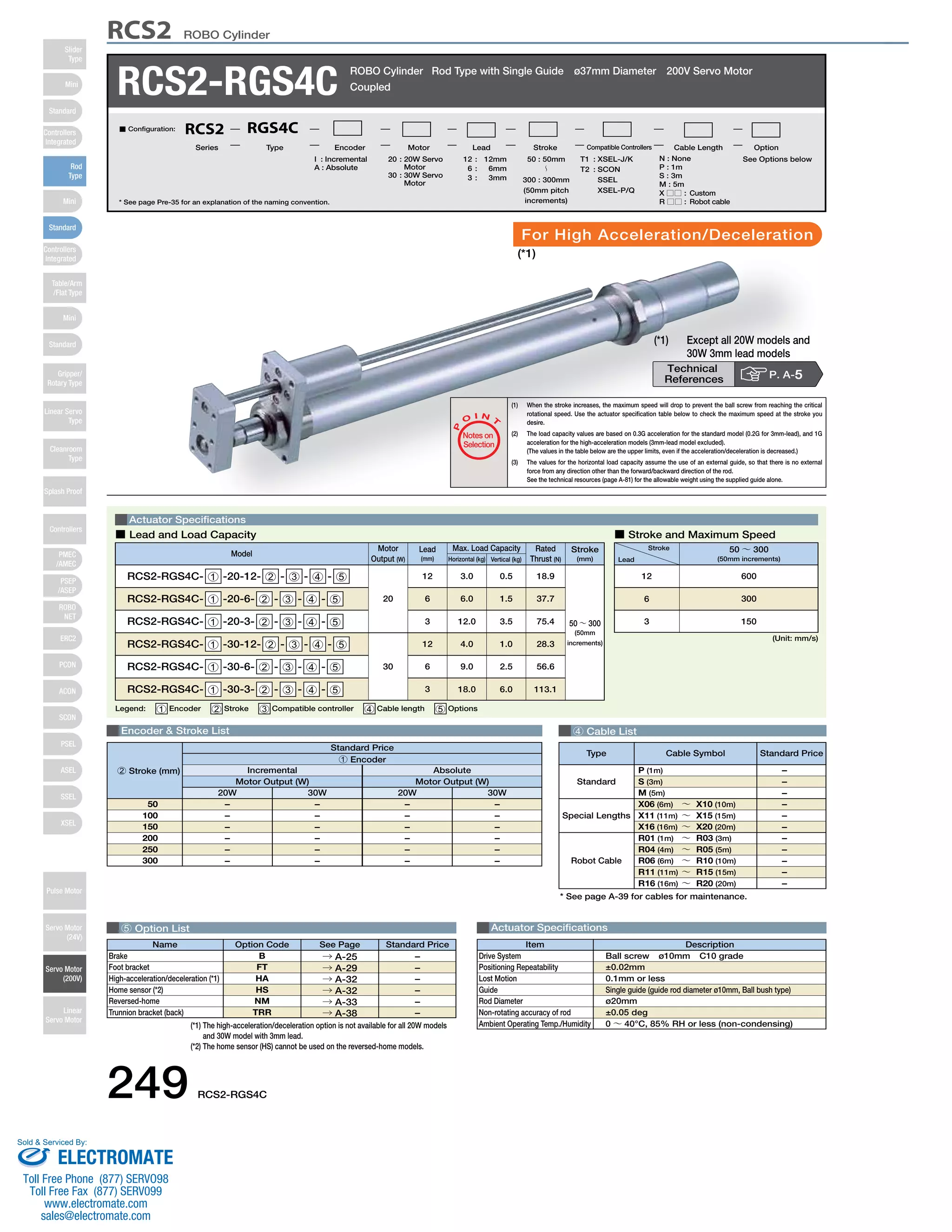
RCS2 ROBO Cylinder
*3. The orientation of the bolt will vary depending on the product.
50
81
Bracket A
11 st 3
Bracket B
ME
16
9
47 (width
across flats)
36 (width
across flats) *3
19 (width across flats) *3
Nut A
Nut B
ø37
L
ℓ 19 m
1
63 (st+11)
30
50
(st+74)
Home
Shaft overhang at SE
41
3 3
st
M40×1.5
(effective screw thread range 19.5)
22
ø10 (guide rod OD)
ø20 (rod OD)
ø52.8
M30×1.5 M40×1.5
ø40.2
8 38 10
50
4-M5
4-C2
8
81
26 36.5
22 50
15 29
37
4-C2
59
15 36.5
6-M5
through-hole
20
30
10 10 26.5
Secure at least 100
(ø50)
(ø48)
Bracket A
Bracket B
16 47
9
47 (width across flats)
36 (width
19 (width across flats)
across flats)
Nut A
Nut B
ø37
L
ℓ 19 m
1
63 (st+11)
Nut A
Bracket A Bracket B
Nut B
40°
3 Compatible Controllers
The RCS2 series actuators can operate with the controllers below. Select the controller according to your usage.
For Special Orders P. A-9
Dimensions
*1. The motor-encoder cable is connected here. See page A-39 for details on cables.
*2. When homing, the rod moves to the ME; therefore, please watch for any interference with the surrounding objects.
ME: Mechanical end SE: Stroke end
RCS2-RGS4C (without brake)
Stroke 50 100 150 200 250 300
ℓ
L
m
20W
30W
20W
30W
Weight (kg)
285.5
300.5
145
1.5
385.5
400.5
245
Stroke 50 100 150 200 250 300
ℓ
L
m
20W
30W
20W
30W
Weight (kg)
328.5
343.5
145
1.7
428.5
443.5
245
123.5
138.5
2.0
528.5
543.5
345
2.4
378.5
393.5
195
1.8
478.5
493.5
295
2.2
578.5
593.5
395
2.6
RCS2-RGS4C (with brake)
80.5
95.5
1.8
485.5
500.5
345
2.2
335.5
350.5
195
1.6
435.5
450.5
295
2.0
535.5
550.5
395
2.4
■ Dimensions/Weight by Stroke
Name External View Model Description Max. Positioning Points Input Voltage Power Supply Capacity Standard Price See Page
Positioner Mode
Pulse Train Input
Control Type
Program Control 1-6
Axes Type
SSEL-C-1-201-NP-2-3
SSEL-C-1-30D12-NP-2-3
XSEL-4-1-201-N1-EEE-2-5
XSEL-4-1-30D12-N1-EEE-2-5
Solenoid Valve Mode
Positioning is possible
for up to 512 points
512 points
Single-Phase AC
100V
Single-Phase AC
200V
3-Phase AC
200V
(XSEL-P/Q only)
Maximum
360VA
* Single-axis model
operated at 150W
Operable with the same
controls as the solenoid
valve.
7 points
Dedicated to serial
communication
64 points
Dedicated to Pulse Train
Input
(−)
Programmed operation
is possible
Operation is possible on
up to 2 axes
Programmed operation
is possible
Operation is possible on
up to 6 axes
20000 points
20000 points
SCON-C-201-NP-2-3
SCON-C-30D12-NP-2-3
→ P547
→ P577
→ P587
–
–
–
Serial Communication
Type
Program Control 1-2
Axes Type
* For SSEL and XSEL, only applicable to the single-axis model.
* 1 is a placeholder for the encoder type (I: incremental / A: absolute).
* 2 is a placeholder for the code "HA" if the high-acceleration/deceleration option is specified.
* 3 is a placeholder for the power supply voltage (1: 100V, 2: single-phase 200V).
* 4 is a placeholder for the XSEL type name ("J", "K", "P", "Q").
* 5 is a placeholder for the power supply voltage (1: 100V, 2: single-phase 200V, or 3: three-phase 200V).
RCS2-RGS4C 250
Slider
Type
Mini
Standard
Controllers
Integrated
Rod
Type
Mini
Standard
Controllers
Integrated
Table/Arm
/Flat Type
Mini
Standard
Gripper/
Rotary Type
Linear Servo
Type
Cleanroom
Type
Splash Proof
Controllers
PMEC
/AMEC
PSEP
/ASEP
ROBO
NET
ERC2
PCON
ACON
SCON
PSEL
ASEL
SSEL
XSEL
Pulse Motor
Servo Motor
(24V)
Servo Motor
(200V)
Linear
Servo Motor
Sold & Serviced By:
ELECTROMATE
Toll Free Phone (877) SERVO98
Toll Free Fax (877) SERV099
www.electromate.com
sales@electromate.com](https://image.slidesharecdn.com/iaircs2rgs4cspecsheet-141015193630-conversion-gate01/85/Iai-rcs2-rgs4_c_specsheet-2-320.jpg)

This document provides specifications for the RCS2-RGS4C ROBO Cylinder. It includes details on actuator models, load capacities, speeds, strokes, dimensions and weights. Compatible controllers that can operate the cylinders include the SSEL, XSEL, SCON and more. The document also provides diagrams of cylinder components and mounting brackets.


