Downloaded 233 times
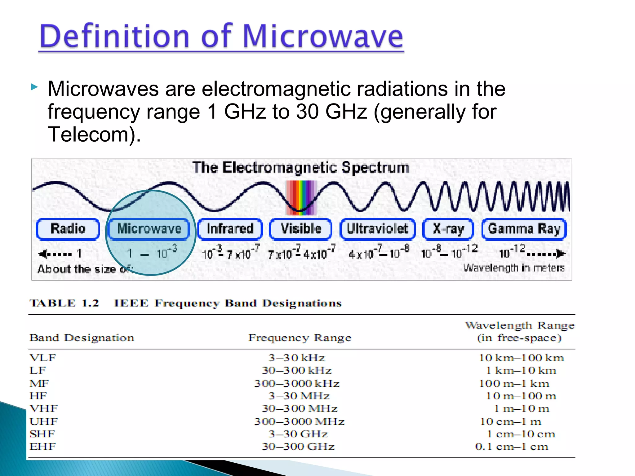


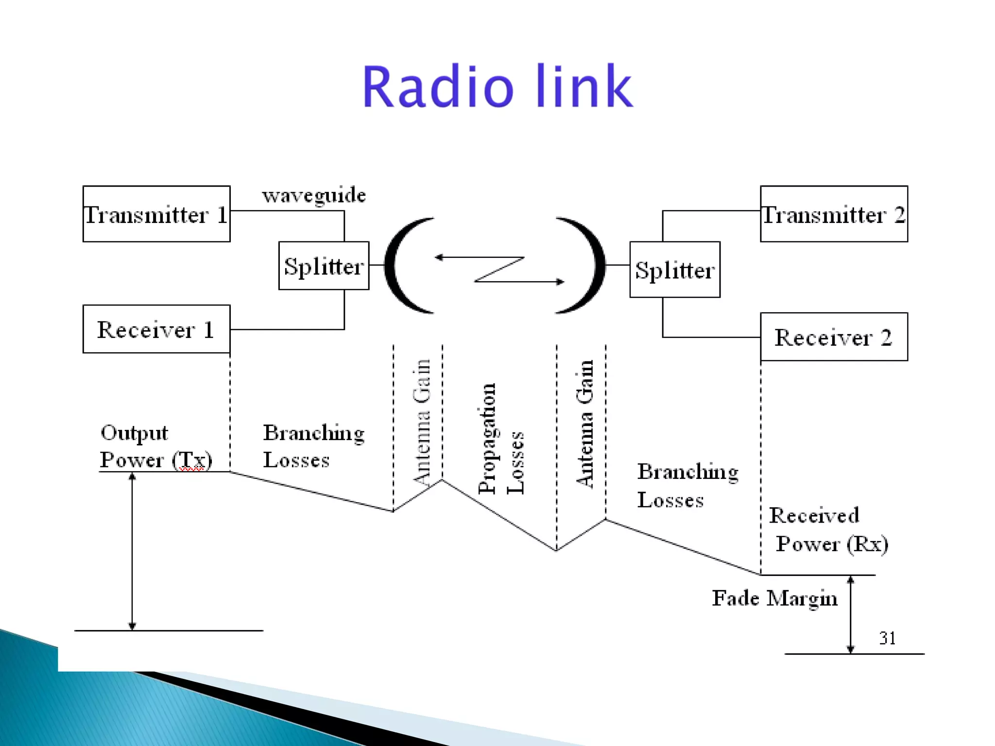


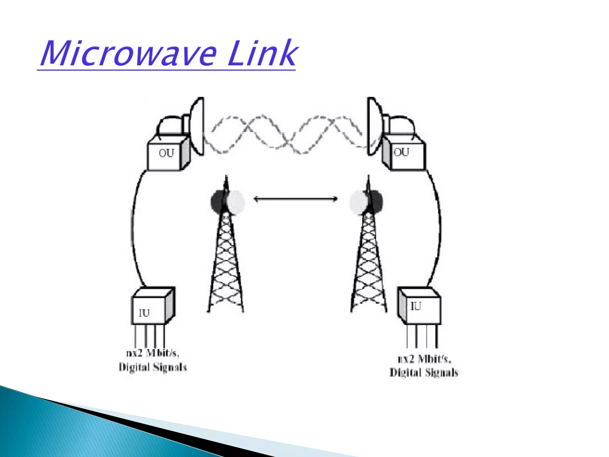


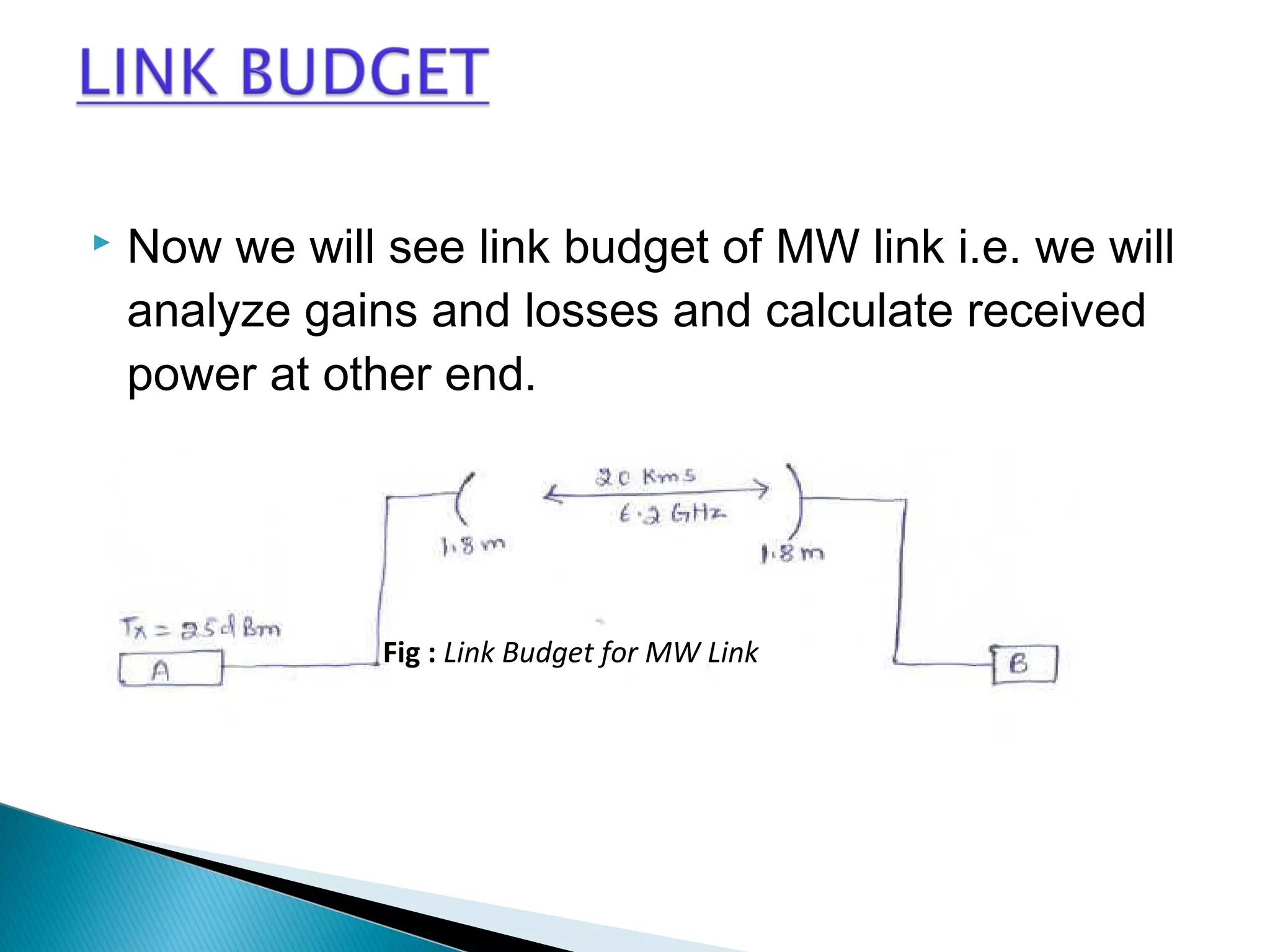
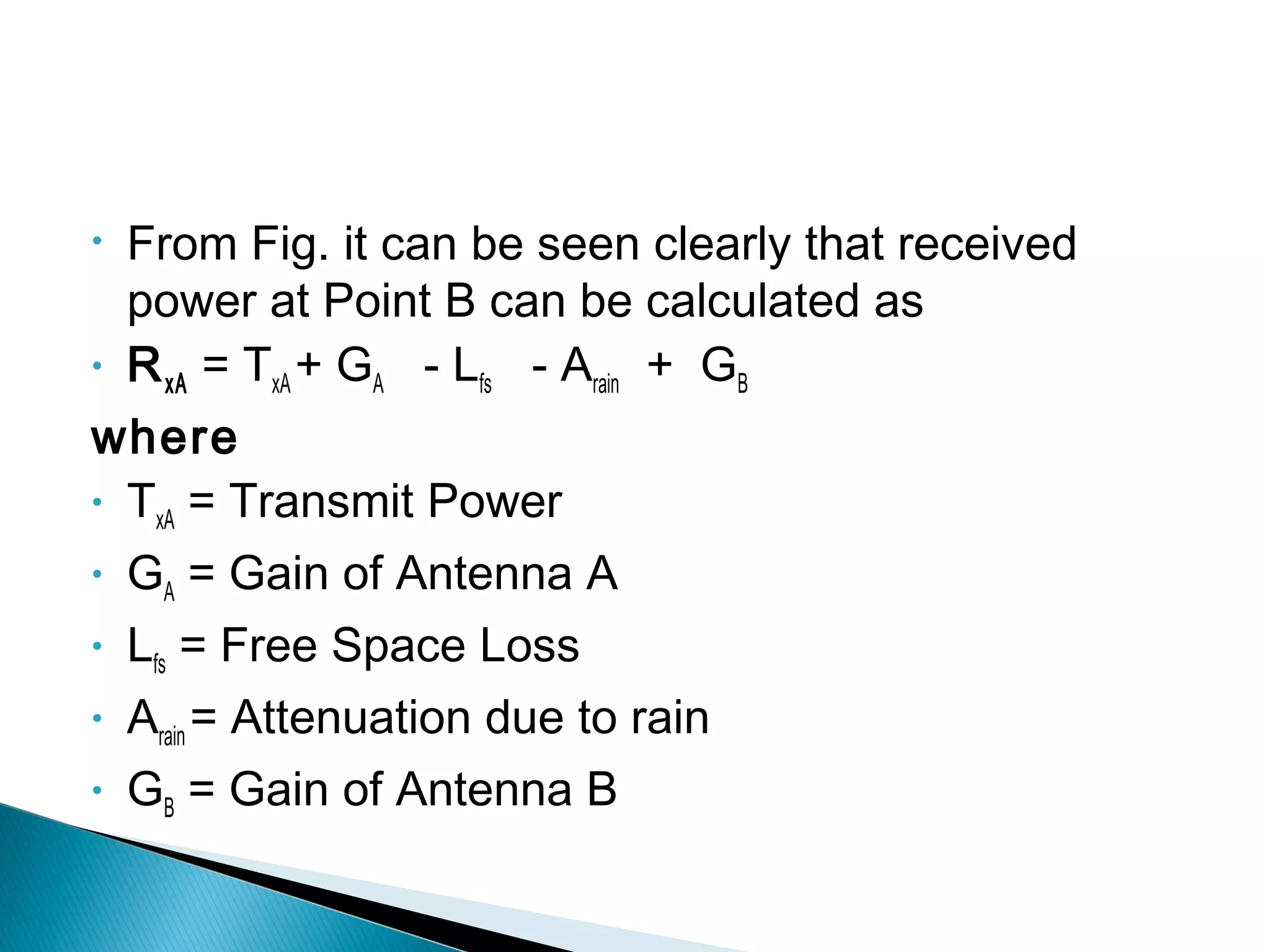


This document discusses the fundamentals of microwave link design. It covers topics such as the frequency ranges used, types of microwave links based on distance (long haul, medium haul, short haul), components of a microwave link including indoor and outdoor units, antennas, and factors that affect microwave link performance such as multipath fading and rain attenuation. It also provides information on polarization, diversity techniques, link budget calculations, and considerations for deploying microwave links.