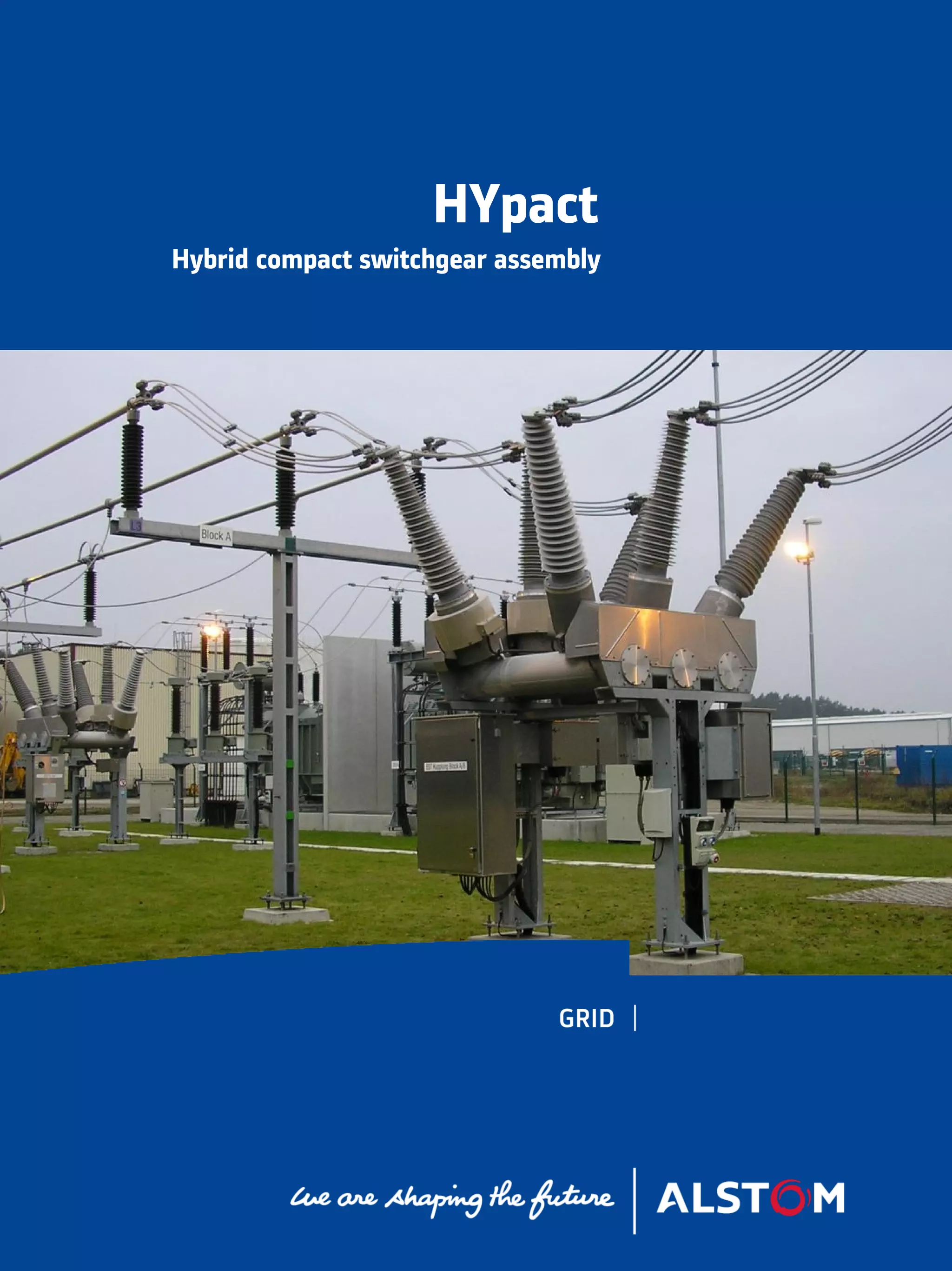
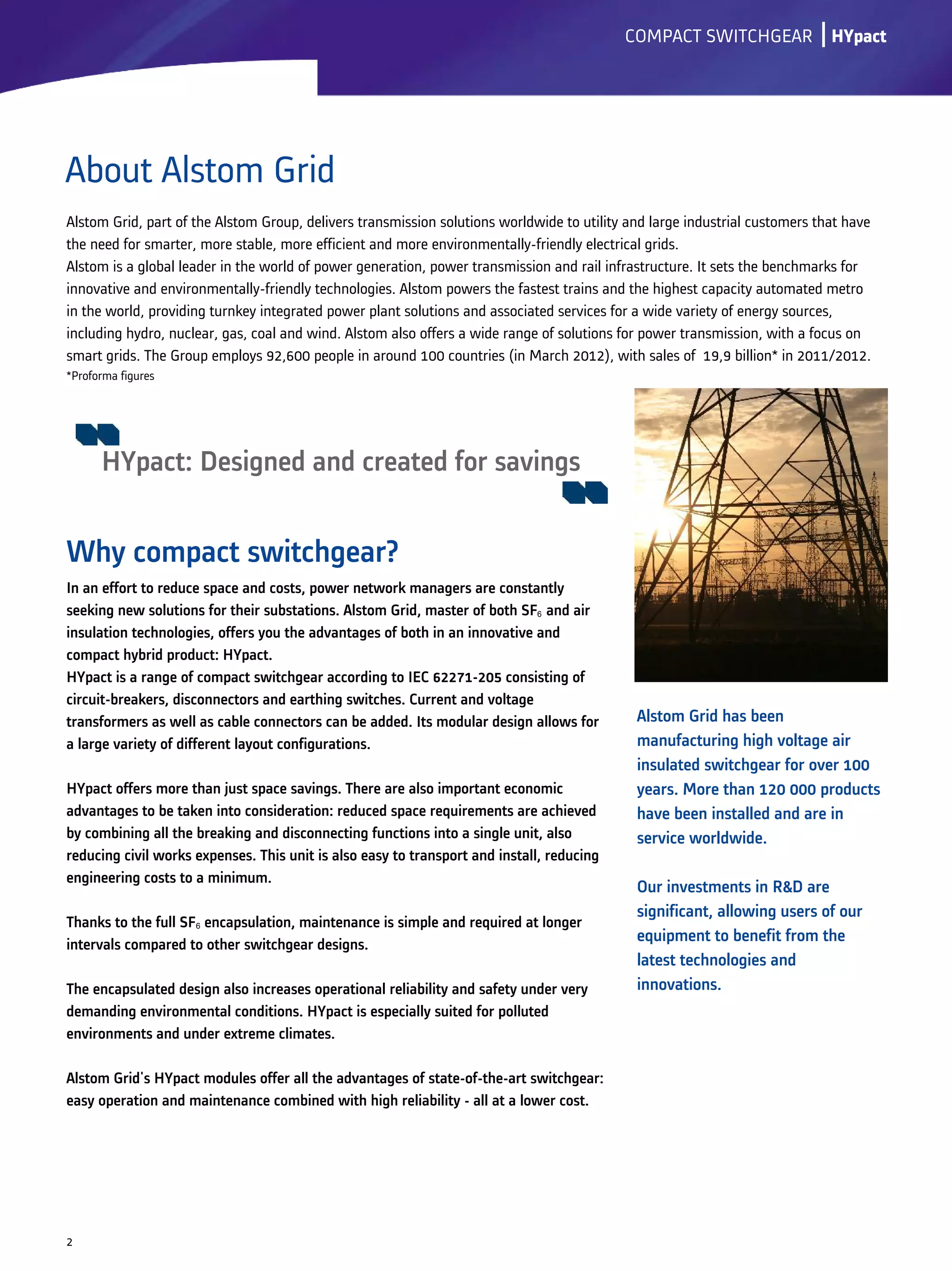
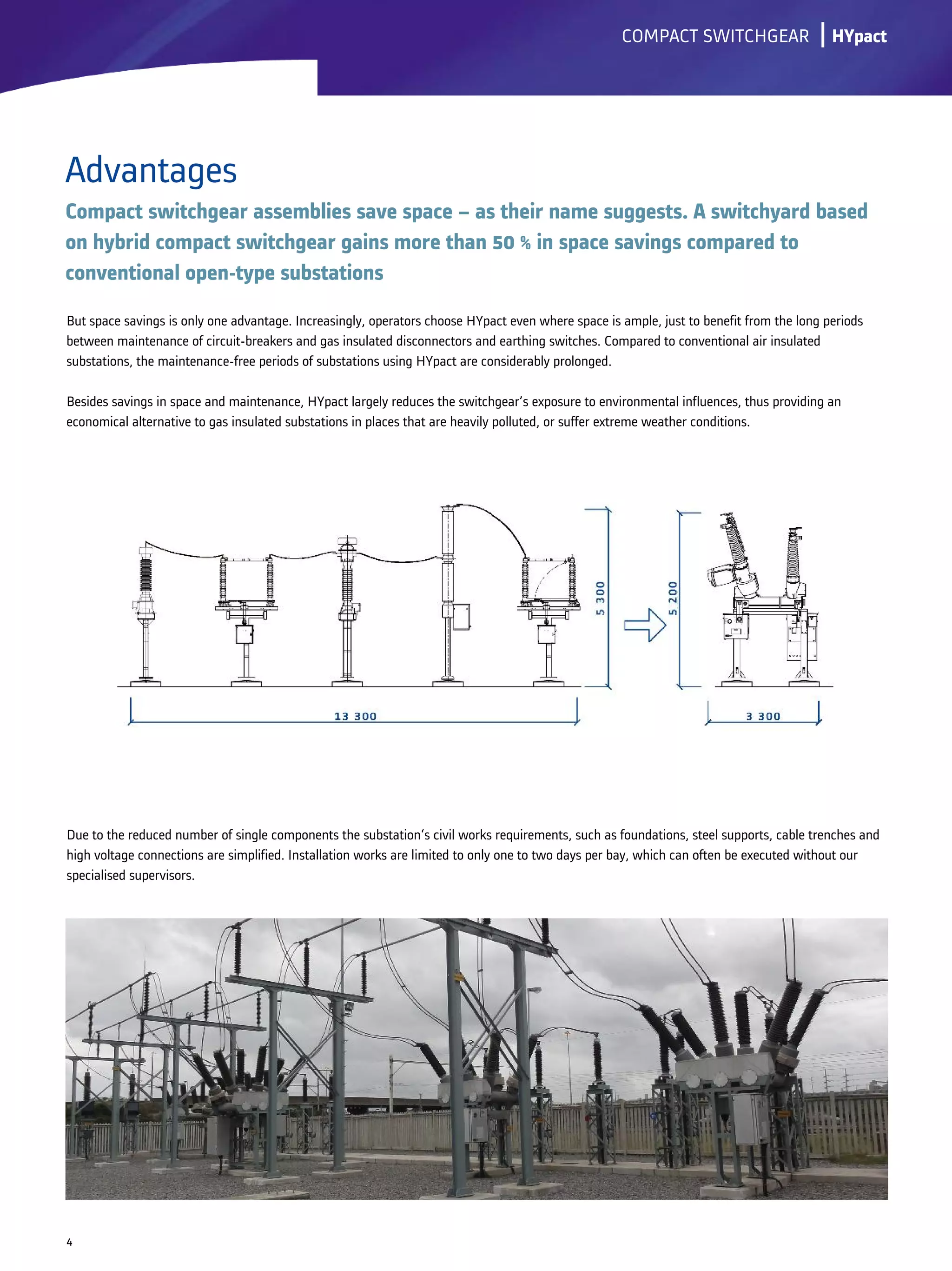
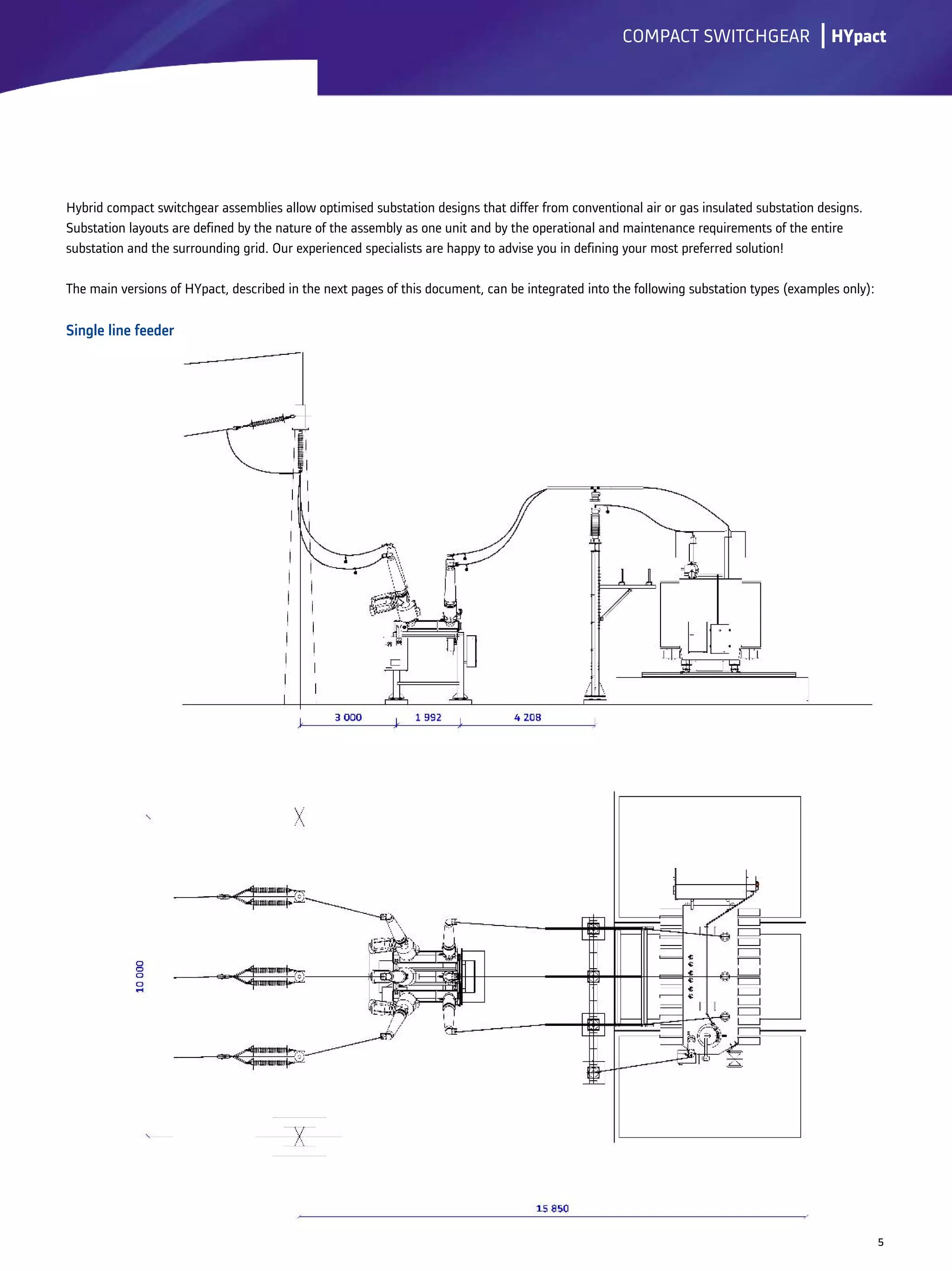
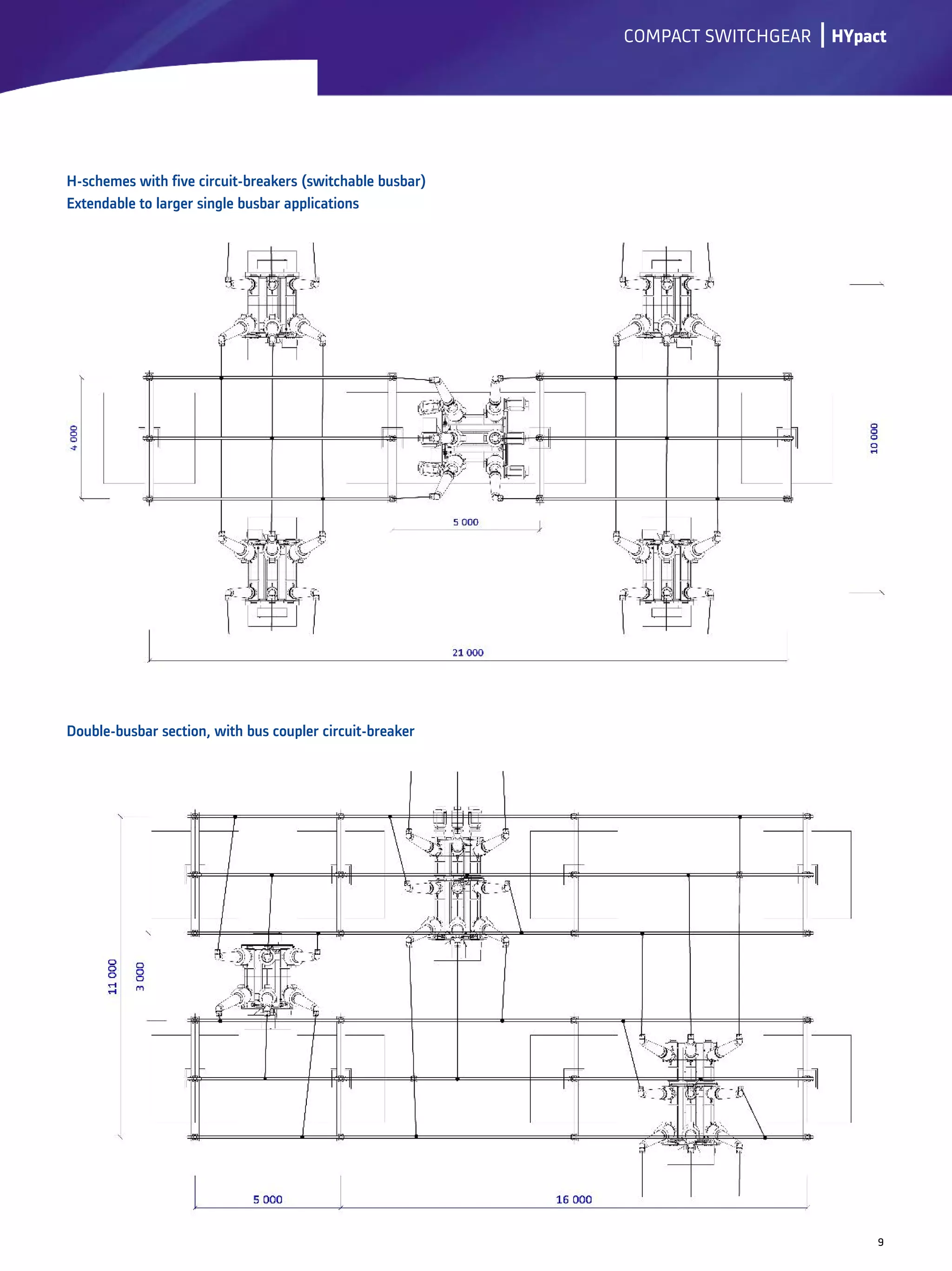
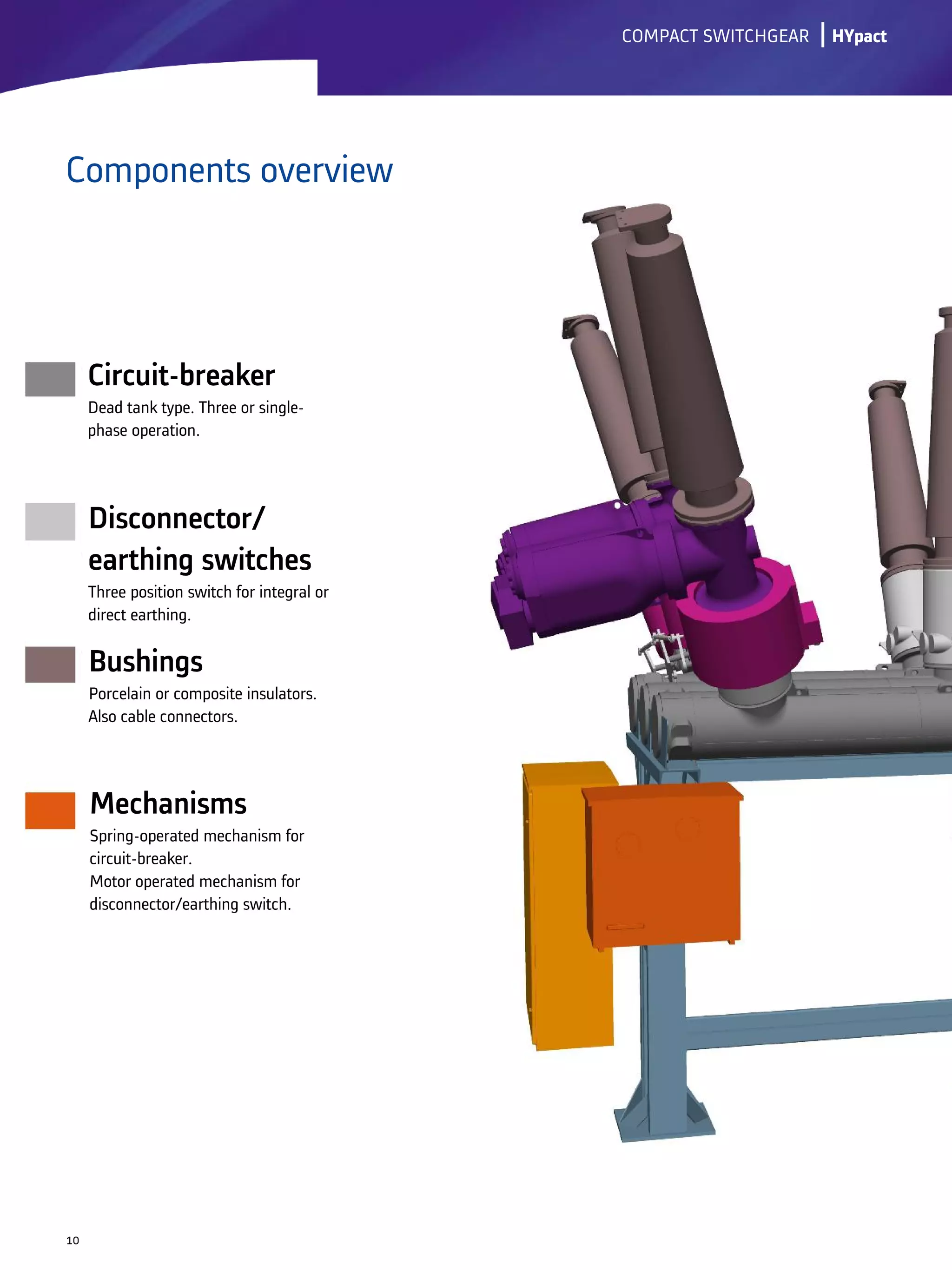
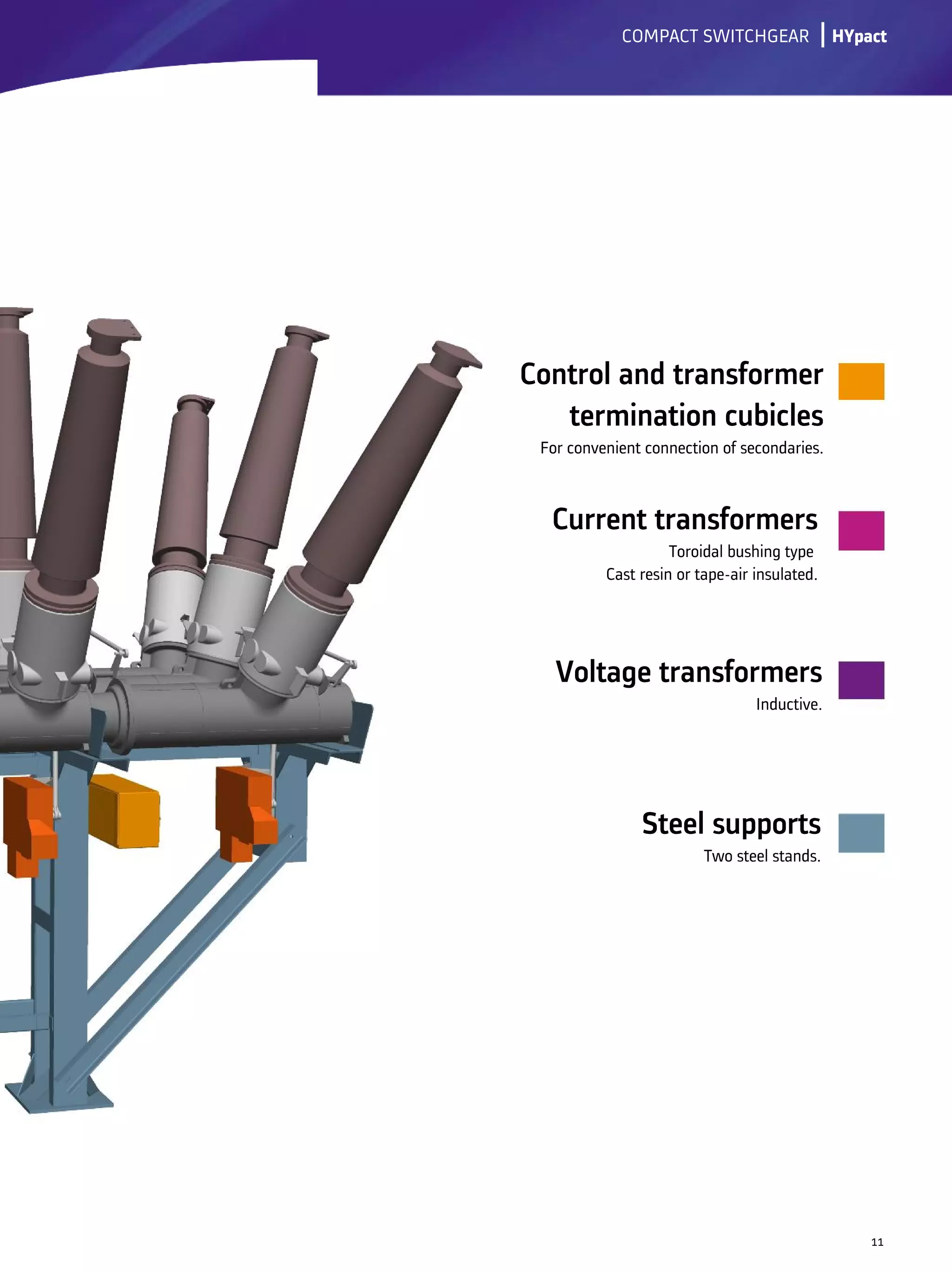
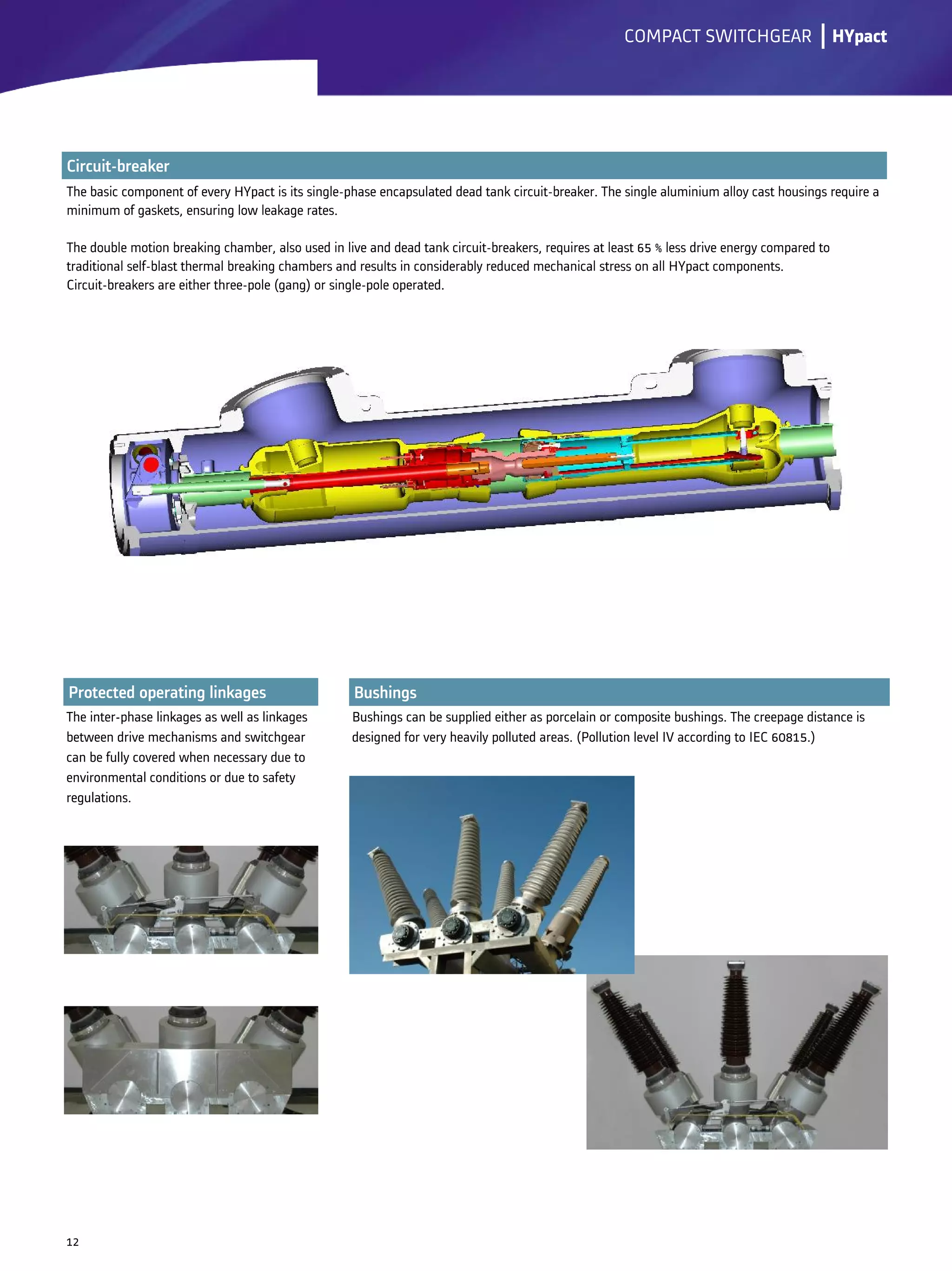
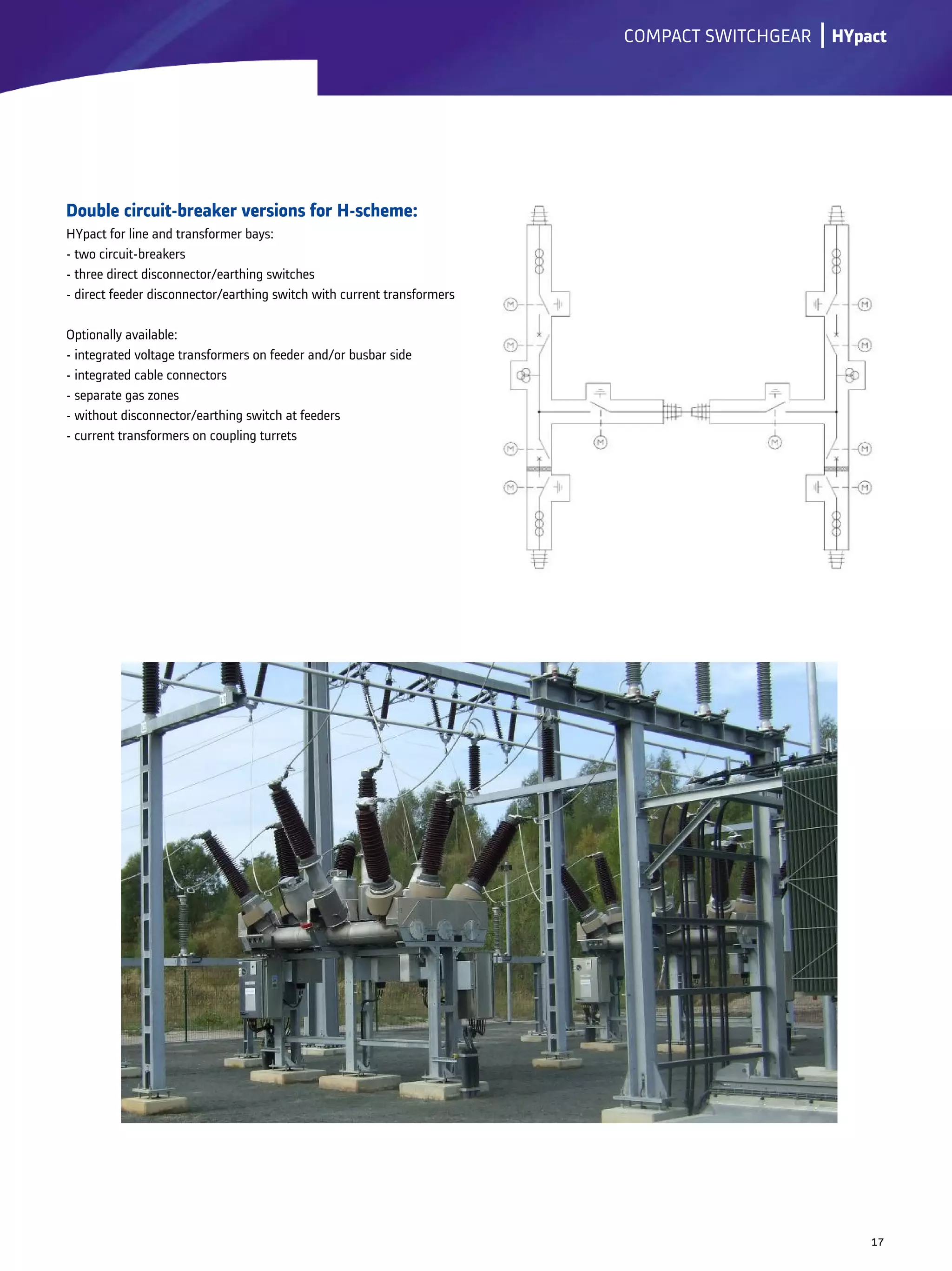
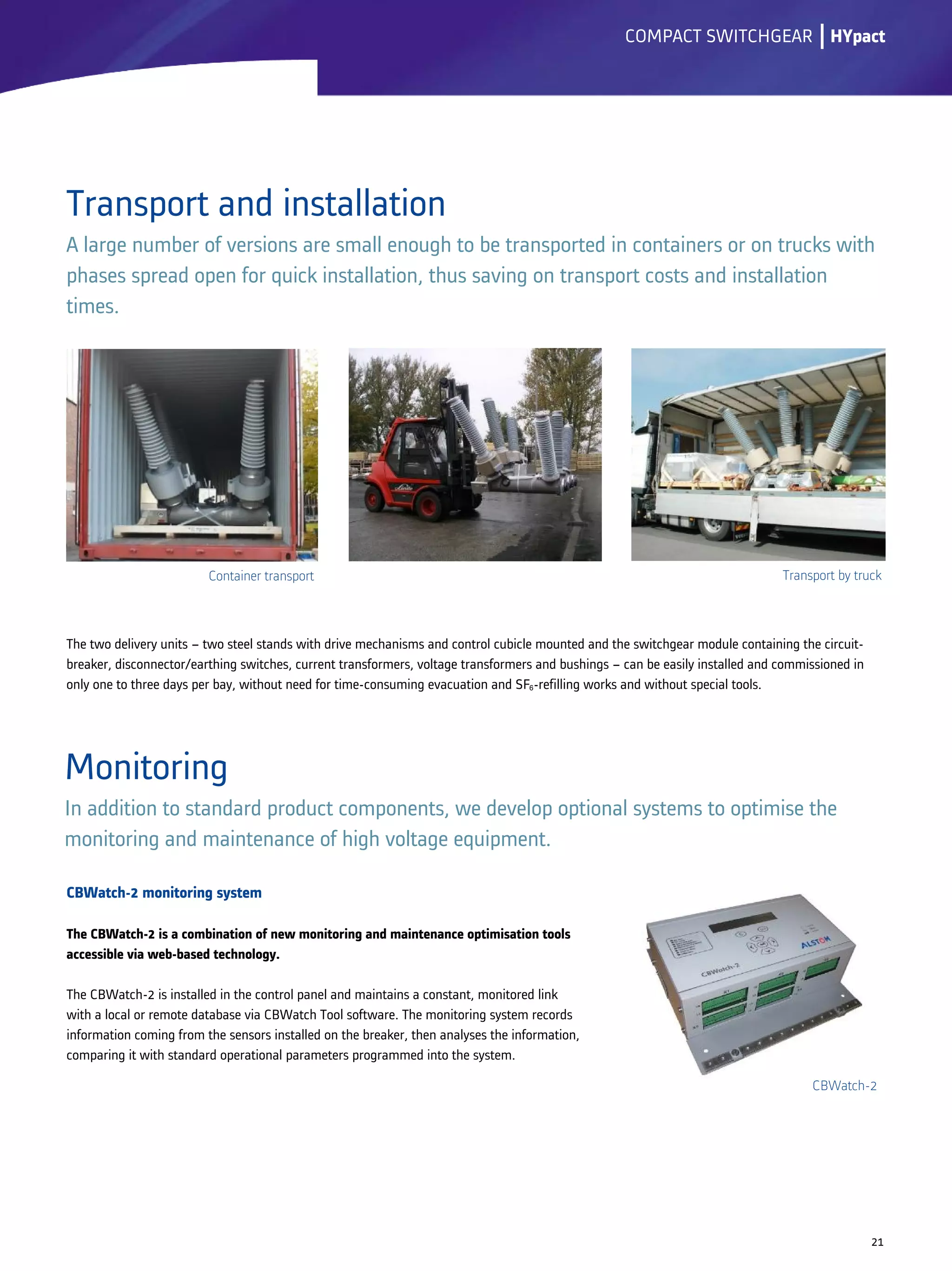
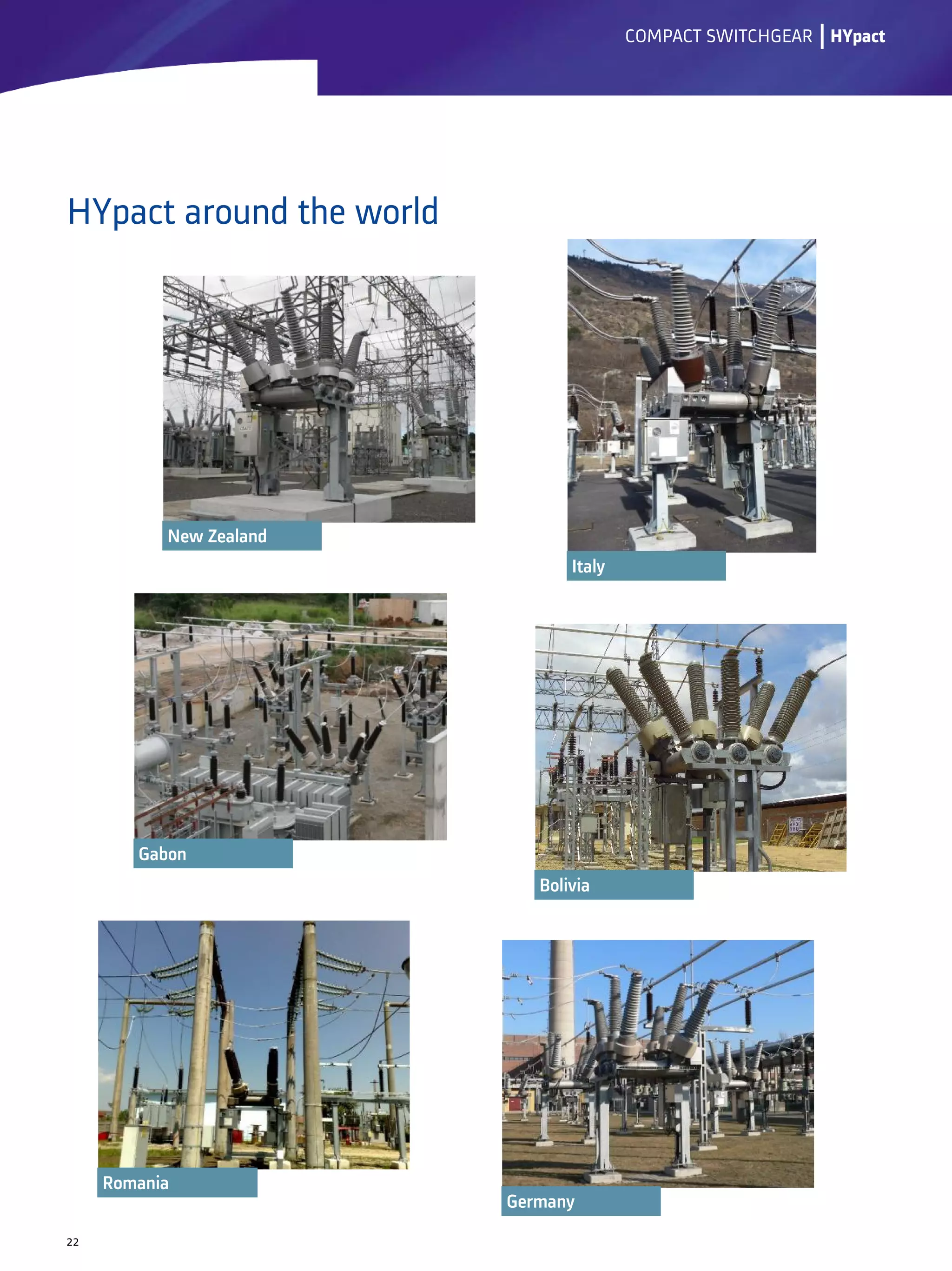
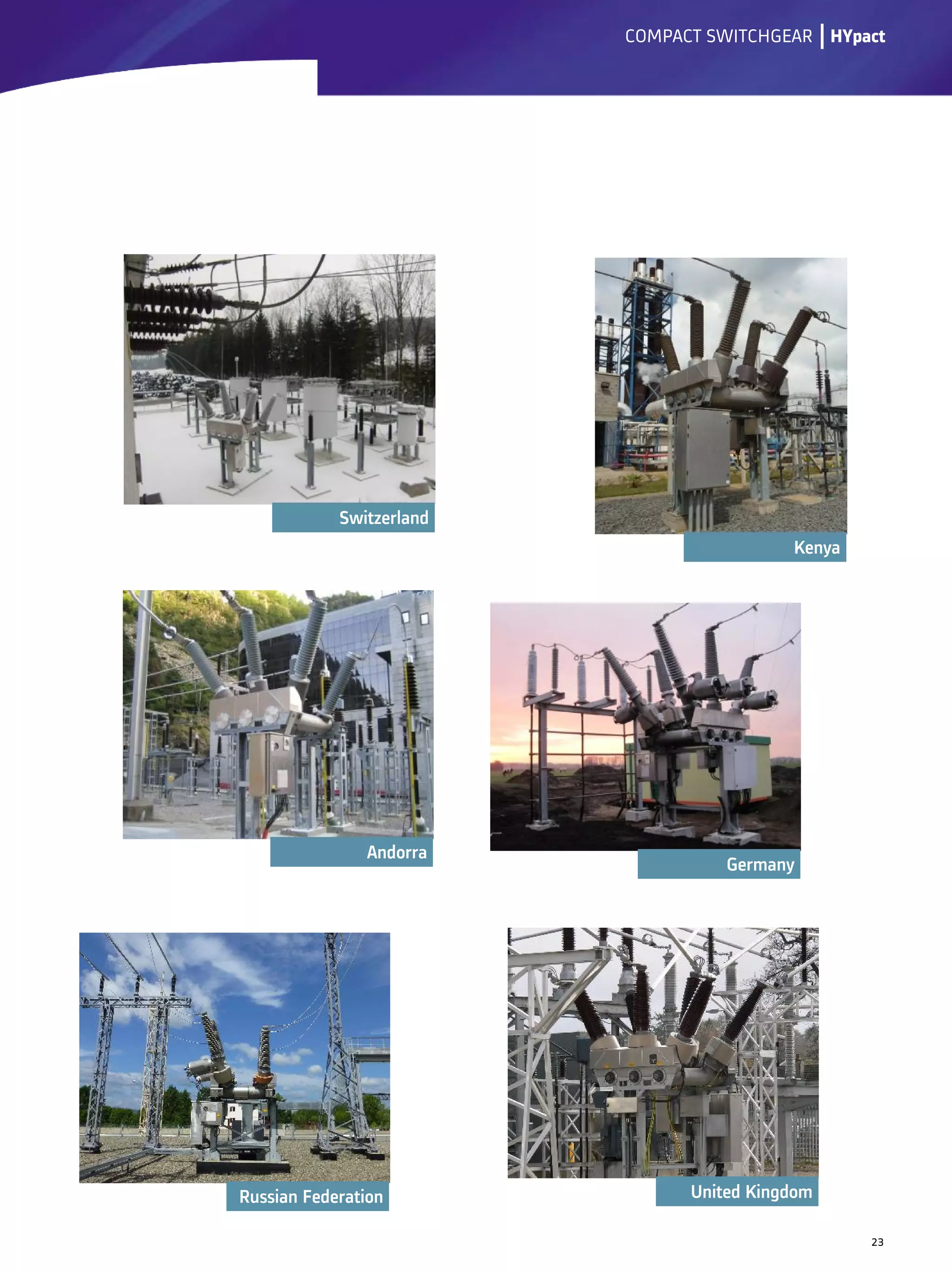
HYpact is a hybrid compact switchgear assembly from Alstom Grid that combines the advantages of SF6 and air insulation technologies. It consists of circuit breakers, disconnectors, and earthing switches in a single modular unit that saves over 50% of space compared to conventional switchgear. HYpact also reduces maintenance needs and offers economic advantages through its modular design and reduced civil works. It is well-suited for demanding environmental conditions and various substation configurations due to its flexibility and robust encapsulated design.
EXECUTIVE SUMMARY
This technical brochure specifies and explains the primary elements of the sag-tension
calculation process, a process which is essential to the design and construction of
overhead lines. The various mathematical tools and conductor data considered herein are
used to predict sag and tension of catenaries at the full range of conductor temperatures
and ice and wind loads that occur over the rather long life of an overhead power line.
The goal of the document is not to develop a unique or “best” calculation method, but to
describe the overall process and explain the common calculation methods.
Introduction
Historically, for most overhead transmission lines, the sag of conductors (or tension) is
measured at the time of construction when the line is not energized. At the time of
installation, the conductors are at a temperature of 10oC to 35oC and tensioned to no more
than 10% to 30% of their rated tensile strength. Once the line is constructed, the phase
conductors may be subject to high temperatures during periods of high electrical loading
and both the lightning shield wires and phase conductors must remain intact during high
ice and wind load events for an expected useful life of 40 years or more. Under all
foreseeable conditions, the conductors must not break under high tension, fatigue under
persistent wind-induced motions, nor sag such that minimum electrical clearances are
compromised.
Efficiency and Loss Evaluation of Large Power TransformersLeonardo ENERGY
All power transformers have very high energy efficiency—the largest are probably the most efficient machines ever devised. However, there is still scope for improvement. Any improvement in the performance of large transformers offers the potential of genuine economic benefits because their throughput and their continuous duty mean that the energy they waste is likewise enormous.
This Application Note discusses the nature of power transformer losses and evaluates those losses from an economic and ecological point of view. There is no general rule on how to design a power transformer for minimum life cycle cost. It has to be approached case by case, based on an estimate of the load profile. This Application Note also tackles the question whether an over-sized transformer is always an energy efficient transformer, and it contains a chapter on the choice of the conductor material.
UNIT - 06 TRANSMISSION LINES AND SUBSTATIONSPremanandDesai
Code of practice for Transmission lines and substations, transmission line materials and their specifications, types of Towers, ACSR conductors and Number of Disc insulators in suspension string, strain string, span and height of towers for 66 KV, 110 KV, 220 KV transmission lines, concept of single circuit and double circuit transmission lines, method of calculating the Quantity of transmission line materials, Prepare the schedule of materials
(only) for 66 KV,110 KV and 220 KV single circuit transmission lines. 66KV/11KV, 5 MVA Substations- Single Line diagram, list of Electrical equipment's/ materials (only) and their
specifications.
Design aspects of high voltage transmission linejournalBEEI
The transmission lines are very important in the transmitted of electrical power, and the process of selecting the voltage of the line is an important task in the design and implementation process. The process of transferring electrical power from one side then onto the next place for long away. While maintaining the percentage regulation within the permissible limits is an important problem in the transfer of energy. In electrical transmission line there are important elements are resistance, inductance and capacitance. The purpose of this paper is to study and calculate economic high-tension voltage and selection of overhead line conductor ACSR.
Optimal Cable Sizing in PV Systems: Case StudyLeonardo ENERGY
It is often beneficial to over-size the cross-section of electricity cables compared to the standard values that follow out of voltage and current calculations. In the large majority of cases, oversizing has a positive influence on the Life Cycle Cost of the installation. The investment in larger cable is easily paid back by the reduction of Joule losses inside the cable and the subsequent savings on electricity bills.
When the cable is part of a photovoltaic (PV) installation, the investment in a larger-than-standard cable is paid back even faster than in other installations. This is because the allocated electricity price for a PV installation is higher than the market price thanks to the feed-in tariff or green certificates. In other words: the energy losses that are avoided in a PV installation lead to an even bigger financial reward than in other installations.
Increasing the cable cross section in PV installations also creates additional technical and environmental benefits.
As the AIS (Air-Insulated Substation) is having more limitations, More and more people are going for the Gas-Insulated Substation which is environment friendly as well.
In these presentation, We discussed about theoritical and technological advancement and advantages related to GIS as compared to other substations.
We discussed different parts of the GIS as well as their operations and advantages.
By going through this presentation, you will have idea regarding comparative advantages and disadvantages of both substations.
Catalog busbar ls 06. busduct presentation e series rev 2Dien Ha The
Khoa Học - Kỹ Thuật & Giải Trí: http://phongvan.org
Tài Liệu Khoa Học Kỹ Thuật: http://tailieukythuat.info
Thiết bị Điện Công Nghiệp - Điện Hạ Thế: http://dienhathe.org
Electrical substation (one and half breaker scheme)Sourabh sharma
Double Bus One and Half Breaker Scheme is mostly adopted in high voltage electrical substations (220 KV or 400KV, 700 KV). Due to many advantages of this arrangement like high selectivity, reliability and less cost as compare to other bus arrangements for power stations or switch yards
Cables are often the last component considered during system design even if in many situations cables are the true system’s lifeline: if a cable fails, the entire system may stop. Cable reliability is therefore extremely important, then a cable system should be engineered to last the life of the system in the installation environment for the required application. Environments in which cable systems are being used are often challenging, as extreme temperatures, chemicals, abrasion, and extensive flexing. These variables have a direct impact on the materials used for cable insulation and jacketing as well as the construction of the cable. Using a systematic approach will help ensure that designer select the best cable for the required application in the installation environment. This lessons will provide students main guidelines for perform this approach.
This article describes ABB power supply solutions and communication and control system technology used in the Rio Tinto Alcan ISAL Smelter Production Upgrade project.
Authors: Bjarni Jonsson (RTA), Halflidi Loftsson (Staki Automation ehf.), Max Wiestner (ABB product group Aluminium)
CÔNG TY CỔ PHẦN HẠO PHƯƠNG
Trụ sở chính:
Địa chỉ: Số 88 đường Vĩnh Phú 40, Kp. Hòa Long, P. Vĩnh Phú, Thuận An, Bình Dương.
Văn phòng Hà Nội:
Địa chỉ: Số 95 TT4 – KĐT Mỹ Đình Sông Đà – Phường Mỹ Đình – Q. Nam Từ Liêm – Hà Nội
Chi nhánh Cambodia:
Địa chỉ: The Park Land SenSok, Borey Chip Mong, House Number 22, P11.Sangkat Phnom Penh Thmey, Khan San Sok, Phnom Penh.
Email: cs@haophuong.com – Website: haophuong.com
Facebook: https://www.facebook.com/haophuongcompany/
HOTLINE: 1800 6547
Bảng giá máy cắt không khí ACB Easypact EVS schneider
Long Nguyễn đại lý phân phối máy cắt không khí Schneider tại Việt Nam
http://longnguyenvn.com/category/acb-evs-schneider
Beeteco.com – website TMĐT chuyên phân phối các thiết bị điện công nghiệp, tự động hóa: Biến tần, PLC, MCB, MCCB, Contactor, đèn báo nút nhấn relay từ các thương hiệu hàng đầu quốc tế như: Fuji Electric, Fuji Engineering, Schneider, LS, Mitsubishi Electric, Himel, Autonics, IDEC IZUMI….
Mọi thắc mắc về giá cả, thông tin sản phẩm vui lòng liên hệ Hotline: 0909.41.61.43
PCTL AUTOMATION LTD. is an electrical engineering solution provider company. Specializing in design, manufacturing and servicing of electrical switchboards,Automation systems, Servo Voltage Regulators and customised solutions for both commercial and industrial environments.
Moving to 66kV: Are current switchgears and transformers adequate?Torben Haagh
When moving to 66kV, availability and compatibility of switchgears and transformers for 66kv installations can be a challenge. Is the industry ready to face the related challenges such as high prices, small availability and installation difficulties? Find out more details in the article here: http://bit.ly/-Article_MovingTo66kV
2. HYpact: Designed and created for savings
Why compact switchgear?
lCOMPACT SWITCHGEAR
About Alstom Grid
2
In an effort to reduce space and costs, power network managers are constantly
seeking new solutions for their substations. Alstom Grid, master of both SF6 and air
insulation technologies, offers you the advantages of both in an innovative and
compact hybrid product: HYpact.
HYpact is a range of compact switchgear according to IEC 62271-205 consisting of
circuit-breakers, disconnectors and earthing switches. Current and voltage
transformers as well as cable connectors can be added. Its modular design allows for
a large variety of different layout configurations.
HYpact offers more than just space savings. There are also important economic
advantages to be taken into consideration: reduced space requirements are achieved
by combining all the breaking and disconnecting functions into a single unit, also
reducing civil works expenses. This unit is also easy to transport and install, reducing
engineering costs to a minimum.
Thanks to the full SF6 encapsulation, maintenance is simple and required at longer
intervals compared to other switchgear designs.
The encapsulated design also increases operational reliability and safety under very
demanding environmental conditions. HYpact is especially suited for polluted
environments and under extreme climates.
Alstom Grid's HYpact modules offer all the advantages of state-of-the-art switchgear:
easy operation and maintenance combined with high reliability - all at a lower cost.
HYpact
Alstom Grid, part of the Alstom Group, delivers transmission solutions worldwide to utility and large industrial customers that have
the need for smarter, more stable, more efficient and more environmentally-friendly electrical grids.
Alstom is a global leader in the world of power generation, power transmission and rail infrastructure. It sets the benchmarks for
innovative and environmentally-friendly technologies. Alstom powers the fastest trains and the highest capacity automated metro
in the world, providing turnkey integrated power plant solutions and associated services for a wide variety of energy sources,
including hydro, nuclear, gas, coal and wind. Alstom also offers a wide range of solutions for power transmission, with a focus on
smart grids. The Group employs 92,600 people in around 100 countries (in March 2012), with sales of 19,9 billion* in 2011/2012.
*Proforma figures
Alstom Grid has been
manufacturing high voltage air
insulated switchgear for over 100
years. More than 120 000 products
have been installed and are in
service worldwide.
Our investments in R&D are
significant, allowing users of our
equipment to benefit from the
latest technologies and
innovations.
3. Research & development
Leadership in technology is our hallmark.
Year after year, Alstom Grid continues to
build on the technical reputation of our
transmission and distribution products,
services and solutions. Our international
presence allows us to draw a maximum of
synergies from teamwork and to engage in
fruitful cooperation with local universities
and scientific bodies.
Alstom Grid in Kassel is the competence
centre for circuit-breakers and compact
switchgear assemblies up to 170 kV. The
internationally accredited high voltage
institute enables us to carry out the research
and development tests required for our
switchgear at the Kassel location.
lCOMPACT SWITCHGEAR
World-class manufacturing facilities
3
Central sales office & competence centre Kassel, Germany
HYpact
Quality
Our markets and customers are changing fast - and so are we!
We are committed to achieving excellence in quality, which is our number one priority.
We strive for customer satisfaction through the improvement of all processes whether in terms
of quality, cost or lead times. This applies to projects and administrative procedures throughout
the entire business process, from tender to final delivery of our products, systems and services.
An ISO 9001-certified quality management system, ISO 14001-certified environmental
management system as well as OHSAS 18001- certified occupational health and safety
management systems govern the entire development and production processes for our high
voltage products and ensure – through regularly conducted audits – the highest standards of
quality for all our products and services.
The strength of a group combining local
experience and global expertise.
The plant in Kassel, Germany is among the largest and most successful production facilities in the world for high voltage products. Switchgear from
Kassel is installed in both outdoor and indoor substations in more than 150 countries around the world, where they ensure an economical and
reliable power supply. With our many years of switchgear manufacturing experience, we will continue to supply customers throughout the world
with high quality switchgear from Kassel.
With our process-oriented organisation, we react flexibly to market requirements and produce high-quality products economically and on schedule.
All the products that leave our plant are distinguished by a high degree of operating safety and reliability and require only limited maintenance.
4. But space savings is only one advantage. Increasingly, operators choose HYpact even where space is ample, just to benefit from the long periods
between maintenance of circuit-breakers and gas insulated disconnectors and earthing switches. Compared to conventional air insulated
substations, the maintenance-free periods of substations using HYpact are considerably prolonged.
Besides savings in space and maintenance, HYpact largely reduces the switchgear’s exposure to environmental influences, thus providing an
economical alternative to gas insulated substations in places that are heavily polluted, or suffer extreme weather conditions.
lCOMPACT SWITCHGEAR
Advantages
Compact switchgear assemblies save space – as their name suggests. A switchyard based
on hybrid compact switchgear gains more than 50 % in space savings compared to
conventional open-type substations
4
Due to the reduced number of single components the substation‘s civil works requirements, such as foundations, steel supports, cable trenches and
high voltage connections are simplified. Installation works are limited to only one to two days per bay, which can often be executed without our
specialised supervisors.
HYpact
5. Hybrid compact switchgear assemblies allow optimised substation designs that differ from conventional air or gas insulated substation designs.
Substation layouts are defined by the nature of the assembly as one unit and by the operational and maintenance requirements of the entire
substation and the surrounding grid. Our experienced specialists are happy to advise you in defining your most preferred solution!
The main versions of HYpact, described in the next pages of this document, can be integrated into the following substation types (examples only):
Single line feeder
lCOMPACT SWITCHGEAR
5
HYpact
6. H-schemes with three circuit-breakersH-schemes with three circuit-breakersH-schemes with three circuit-breakersH-schemes with three circuit-breakers (switchable busbar)
Extendable to larger single busbar applicationsExtendable to larger single busbar applicationsExtendable to larger single busbar applicationsExtendable to larger single busbar applications
lCOMPACT SWITCHGEAR
H-schemes with two circuit-breakers, voltage transformers on busbar side
6
HYpact
8. lCOMPACT SWITCHGEAR
Bus section with bus coupler circuit-breaker (incoming/outgoing feeder and transformer feeder, within one bay section)
8
HYpact
9. Double-busbar section, with bus coupler circuit-breaker
lCOMPACT SWITCHGEAR
H-schemes with five circuit-breakers (switchable busbar)
Extendable to larger single busbar applications
9
HYpact
12. Bushings can be supplied either as porcelain or composite bushings. The creepage distance is
designed for very heavily polluted areas. (Pollution level IV according to IEC 60815.)
lCOMPACT SWITCHGEAR
The inter-phase linkages as well as linkages
between drive mechanisms and switchgear
can be fully covered when necessary due to
environmental conditions or due to safety
regulations.
12
HYpact
13. Connected
Disconnector closed
Earthing switch open
Neutral
Disconnector open
Earthing switch open
lCOMPACT SWITCHGEAR
The three-position switch provides a closed disconnector switch with open earthing switch, an open disconnector switch with open earthing switch
and an open disconnector switch with closed earthing switch. The disconnector and earthing switches are intrinsically interlocked.
Where substation design and operational requirements do not allow for integral earthing, a direct disconnector/earthing switch is provided. Here,
the earthing switch operates independently of the circuit-breaker. Induced currents can be switched according to IEC 62271-102, annex C, class B.
13
Earthing
Disconnector open
Earthing switch closed
HYpact
When required, the disconnectors of both integral and direct disconnector/earthing switches can be reinforced with pre-arcing contacts, enabling
the disconnector to switch bus-transfer currents occurring in large air insulated substations (1600 A - 100 V in accordance with IEC 62271-102,
annex B, class B).
Connected
Disconnector closed
Earthing switch open
Neutral
Disconnector open
Earthing switch open
Earthing
Disconnector open
Earthing switch closed
14. Disconnector/earthing switches are
operated by a three-position motor drive,
allowing for emergency manual operation
too.
All drive mechanisms are mounted on the
steel supports and readily adjusted when
dispatched.
The position of circuit
-breaker and
disconnector/ear
-thing switches is
displayed in a
mechanically linked
mimic diagram,
conveniently visible
from the HYpact’s
front side.
lCOMPACT SWITCHGEAR
14
Epoxy cast resin toroidal current transformers (with or without metal covers) are placed around disconnector/earthing switches so that they do not
need extra space. Their large diameter ensures they can be slipped over bushings and gas works are not required in case these current transformers
need to be replaced.
HYpact
Circuit-breakers are powered by spring-
operated mechanisms from Alstom Grid’s
FK 3-1 series. These drive mechanisms use
the most reliable helical compression springs
and are present in more than a hundred
thousand live and dead tank circuit-breakers,
gas insulated switchgear and compact
switchgear assemblies worldwide.
Current transformers terminate into a separate measuring transformer wiring box serving as convenient interface with the substation’s secondary
wiring. (To be omitted on request.)
Each current transformer can consist of up
to five cores. As the number of cores
depends on the current transformer’s ratio,
number of taps, accuracy and power,
current transformers are always defined by
particular requirements.
At positions without disconnector/earthing
switches, or for particular requirements
concerning the position of the current
transformers, either cast resin or slimmer
tape-air insulated current transformers are
available.
Additional precision indicators show the exact
position of disconnector/earthing switches,
including tolerances permitted.
15. A central bay control is integrated either into the circuit-breaker drive mechanism or into a separate central control cubicle mounted on the
HYpact. The bay control is equipped with conventional relays and contactors or by programmable logic controller. If the bay control is integrated
into the substation protection and control scheme, the switchgear control at bay level can also be avoided.
lCOMPACT SWITCHGEAR
Optionally, HYpact can be upgraded with
intelligent circuit-breaker monitoring
(CBWatch-2).
15
Inductive voltage transformers may be integrated. These gas insulated voltage transformers are
equipped with gas barriers to form separate gas zones.
Integrated cable connectors are optionally available for several types of the most common cable
connector manufacturers, either for dry or liquid type connectors.
HYpact
Pluggable current
contact
Stresscone in
silicone rubber
Insulator in epoxy
resin
Inlet with inner
spring assembly
Clamp support
Screen connection
Cable clamp
XLPE cable
16. Single busbar versions:
Versions for double busbar or H-scheme:
lCOMPACT SWITCHGEAR
Main versions
16
HYpact's modular concept facilitates a variety of configurations suitable for most substation
designs, of which the most prominent are shown below.
HYpact
HYpact for line and transformer bays:
- one circuit-breaker
- one integral disconnector/earthing switch
- current transformers on either, or on both sides
HYpact for line and transformer bays:
- one circuit-breaker
- two selector switch disconnectors, one or
both as disconnector/earthing switch
- direct feeder disconnector/earthing switch
- current transformers on any bushing exit
Optionally available:
- second disconnector/earthing switch
(recommended for switched busbar
application and bus coupler application)
- either disconnector/earthing switch with
direct earthing
- integrated voltage transformers
- integrated cable connectors
Optionally available:
- without feeder disconnector/earthing switch
for transformer bays
- integrated voltage transformers
- integrated cable connectors
- separate gas zones
- reinforced disconnector contacts to switch
bus-transfer currents
HYpact for H-scheme
HYpact for double busbar
17. Double circuit-breaker versions for H-scheme:
HYpact for line and transformer bays:
- two circuit-breakers
- three direct disconnector/earthing switches
- direct feeder disconnector/earthing switch with current transformers
Optionally available:
- integrated voltage transformers on feeder and/or busbar side
- integrated cable connectors
- separate gas zones
- without disconnector/earthing switch at feeders
- current transformers on coupling turrets
lCOMPACT SWITCHGEAR
17
HYpact
18. lCOMPACT SWITCHGEAR
18
The modular concept of HYpact allows
its use in almost all substation layouts
including single and double busbar
applications, cable connectors and
single- and three-phase operation for
indoor and outdoor installations.
• Spring-operated mechanism
FK 3-1
• Rated operating sequence of circuit-breaker
O-0.3s-CO-3 min-CO resp. CO-15s-CO
• Rated supply voltage
From 48 up to 250 Vdc/ac
• Maximum ambient temperature
From -60 °C up to +40 °C (with pure SF6)
HYpact
Type tests
The IEC standard for compact switchgear
assemblies, IEC 62271-205 2008, requires
not only the performance of type test for
each individual device, but also the need to
demonstrate the characteristics of the
assembly in its entirety. Consequently, the
complete HYpact consisting of circuit-
breaker, disconnector, earthing switch and
current transformer has undergone an
extensive type test series, including, but not
limited to power tests, dielectric tests,
mechanical and environmental tests.
Completive devices and functions, e.g. cable
connectors or voltage transformers, have
been tested according to their individual
applicable standards also as part of the
HYpact, to demonstrate that interactions
between the devices and the HYpact do not
limit their individual ratings or those of the
entire assembly.
HYpact type tests have been carried out in
accredited and certified test laboratories.
19. Operation at low temperatures
HYpact perform perfectly in harsh climates, even under heavy snow and ice loads, or at
temperatures down to -60 °C, with pure SF6.
lCOMPACT SWITCHGEAR
19
Due to well-covered movable parts, HYpact
is properly mechanically protected against
the influence of heavy snow and ice-loads.
Additionally, a thermostat-controlled, AC-
powered heating system ensures the reliable
electrical operation of HYpact at
temperatures lower than -30 °C.
Placed at the main tanks, a number of
heating pads and cartridge heaters operate
independently.
Protective covers ensure the all-over heat
distribution and double as safety device
against unintended touching.
Gentle on energy resources, the gas volume
is heated in two steps, dependent from the
ambient temperature.
Starting from -22 °C, the second circuit is
energized at -35 °C for the -45 °C-
application or at -50 °C for the -60 °C-
application.
Tested according to the requirements of
GOST 15150 and 52565 as well as
according to the more severe requirements
of FGC-UES the proper function of HYpact is
ensured even in the event of loss of the
auxiliary power for up to two hours, down to
-60 °C and under wind load.
For areas, designated for temperatures
lower than -45 °C, UV-protective silicone
blankets are used additionally.
Using Alstom’s heating system enables the
operation of HYpact under extremely low
temperature conditions, with pure SF6!
HYpact
20. Seismic qualification
lCOMPACT SWITCHGEAR
20
Due to the low center of gravity and the
compactness particularly of the
encapsulated disconnectors and earthing
switches, HYpact is the ideal switchgear for
areas exposed to high seismic activity. To
optimise the HYpact for use under very
heavy seismic conditions, finite element
method calculations have been carried out.
As a result, HYpacts to be used in
earthquake-prone areas are equipped with
supports made of high yield-strength steel.
For verification of the calculations, the
HYpact was exposed to additional shaking
table tests based on IEEE Std 693TM-2005
High Level, equalling to seismic accelerations
of 0.7 g, which it passed without fail.
HYpact
HYpact under shaking table test
Seismic calculation
21. Transport and installation
A large number of versions are small enough to be transported in containers or on trucks with
phases spread open for quick installation, thus saving on transport costs and installation
times.
CBWatch-2 monitoring system
The CBWatch-2 is a combination of new monitoring and maintenance optimisation tools
accessible via web-based technology.
The CBWatch-2 is installed in the control panel and maintains a constant, monitored link
with a local or remote database via CBWatch Tool software. The monitoring system records
information coming from the sensors installed on the breaker, then analyses the information,
comparing it with standard operational parameters programmed into the system.
lCOMPACT SWITCHGEAR
Monitoring
In addition to standard product components, we develop optional systems to optimise the
monitoring and maintenance of high voltage equipment.
21
The two delivery units – two steel stands with drive mechanisms and control cubicle mounted and the switchgear module containing the circuit-
breaker, disconnector/earthing switches, current transformers, voltage transformers and bushings – can be easily installed and commissioned in
only one to three days per bay, without need for time-consuming evacuation and SF6-refilling works and without special tools.
HYpact
Container transport Transport by truck
CBWatch-2