Download as PDF, PPTX


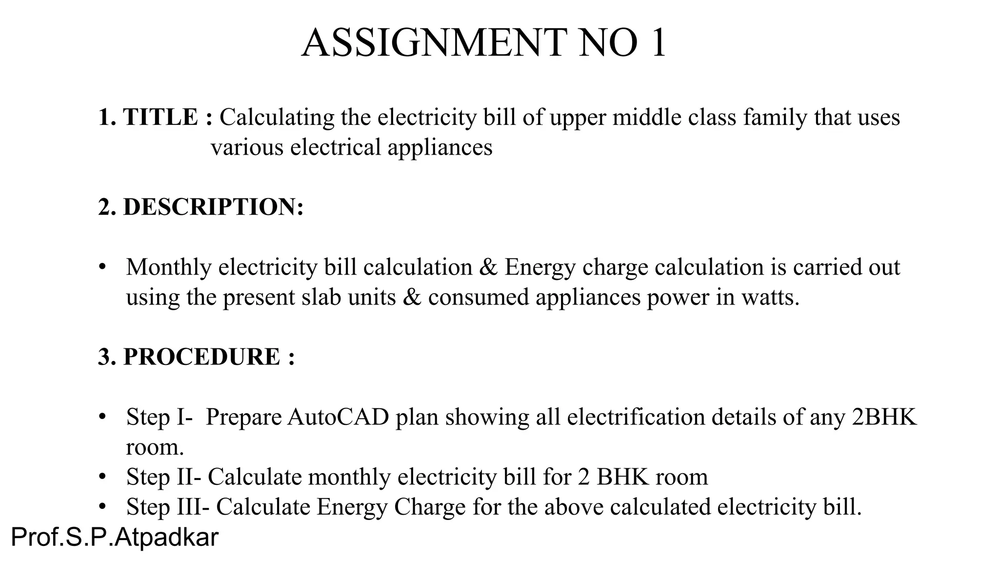


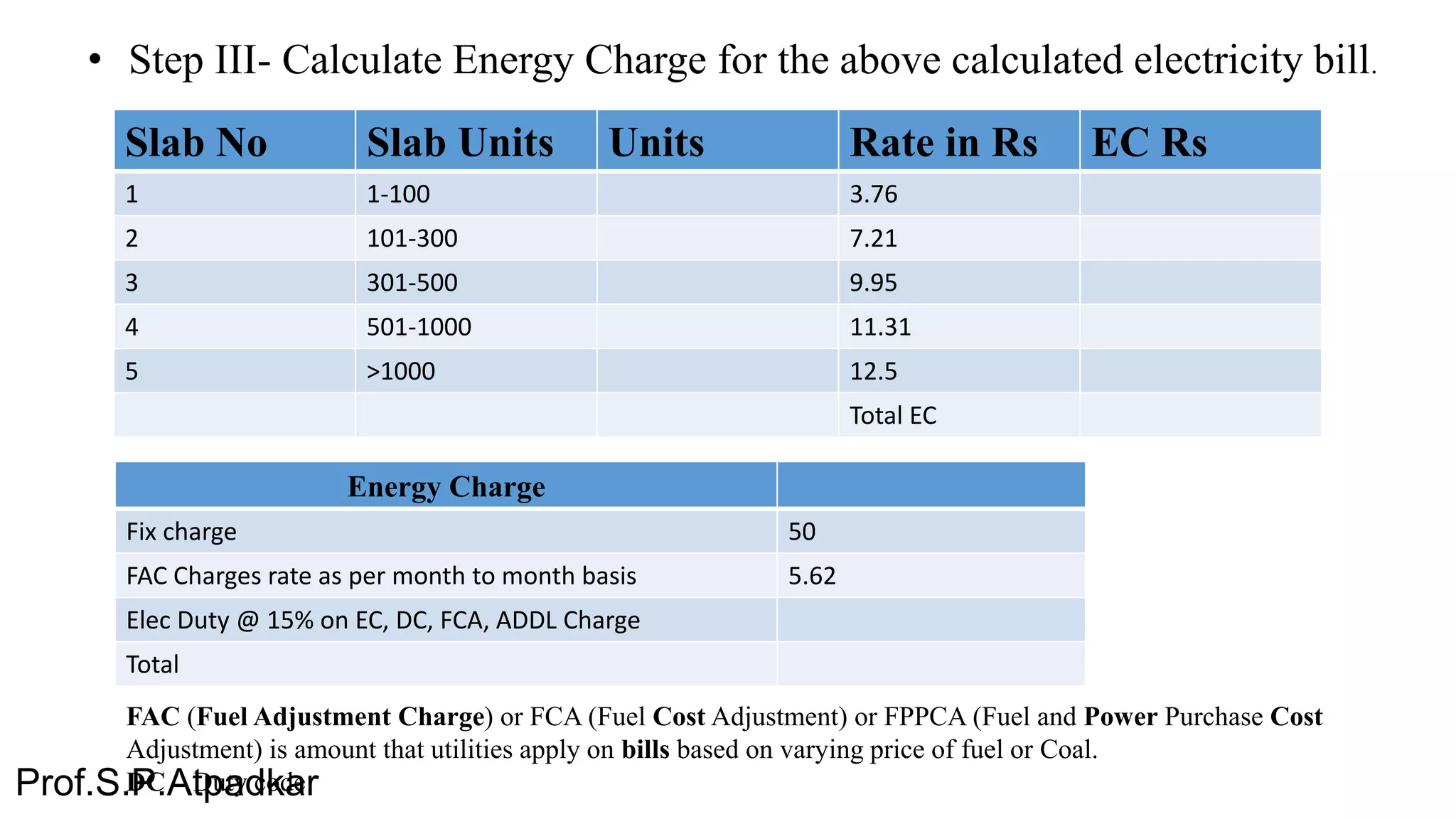


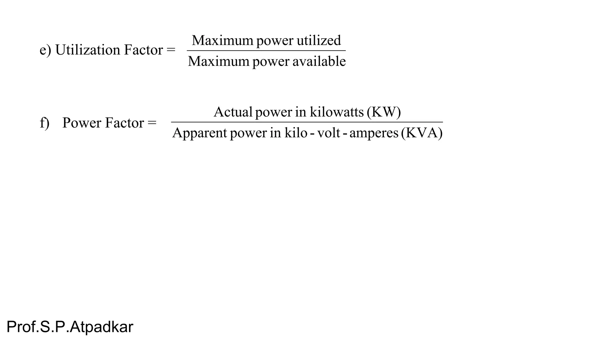


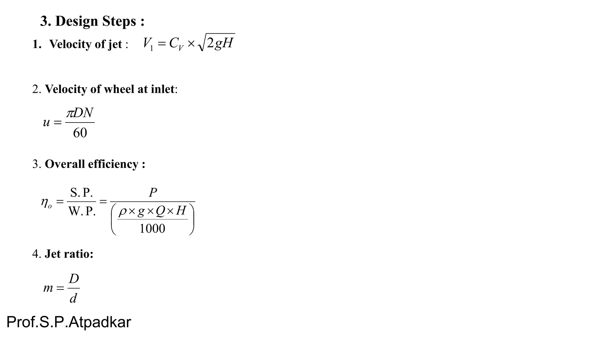
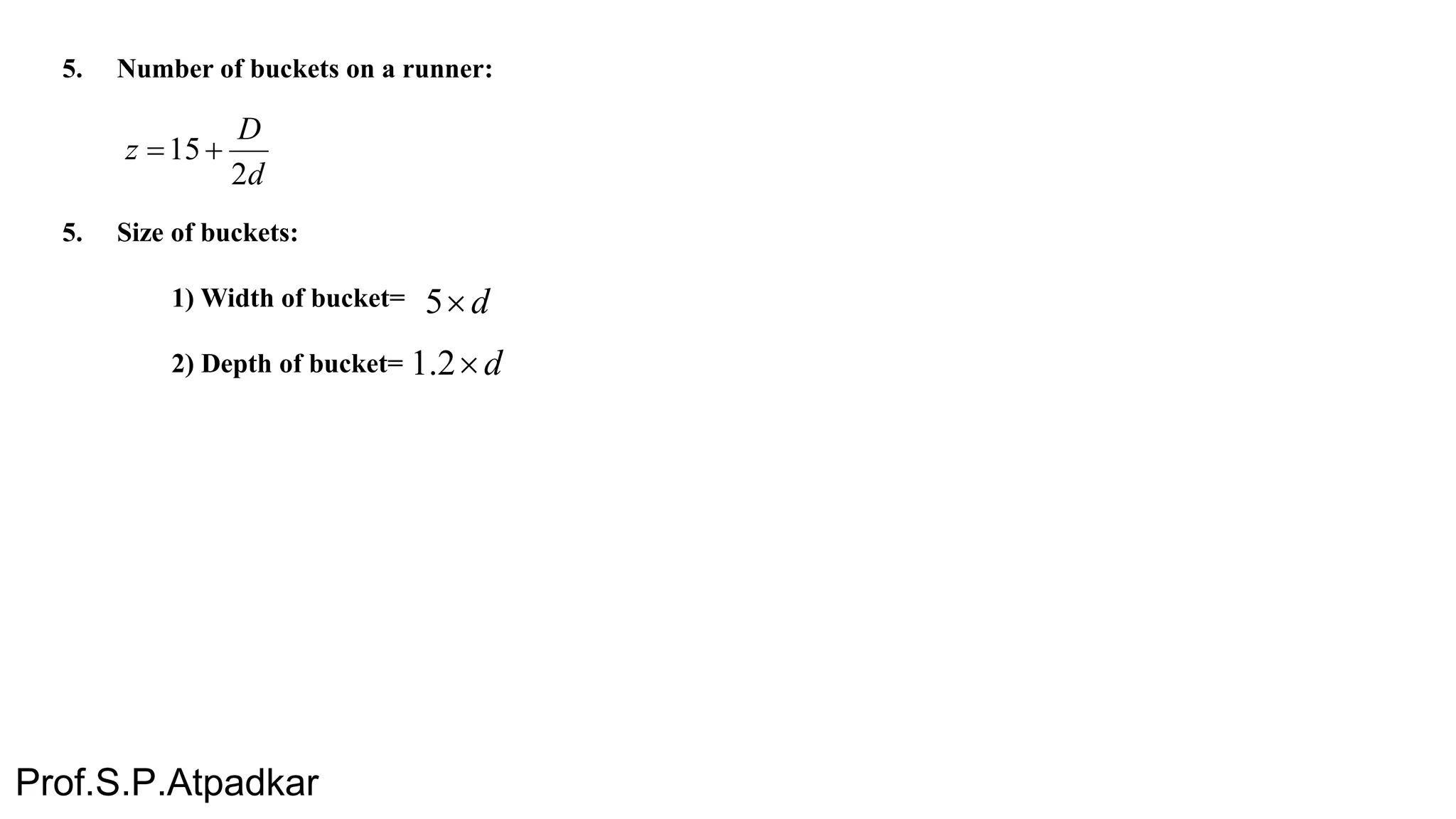


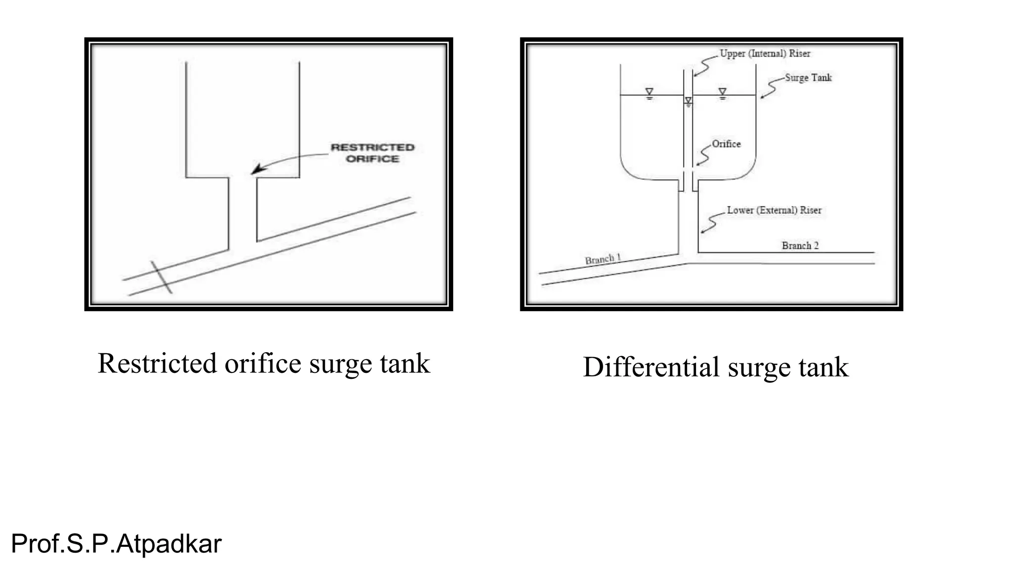


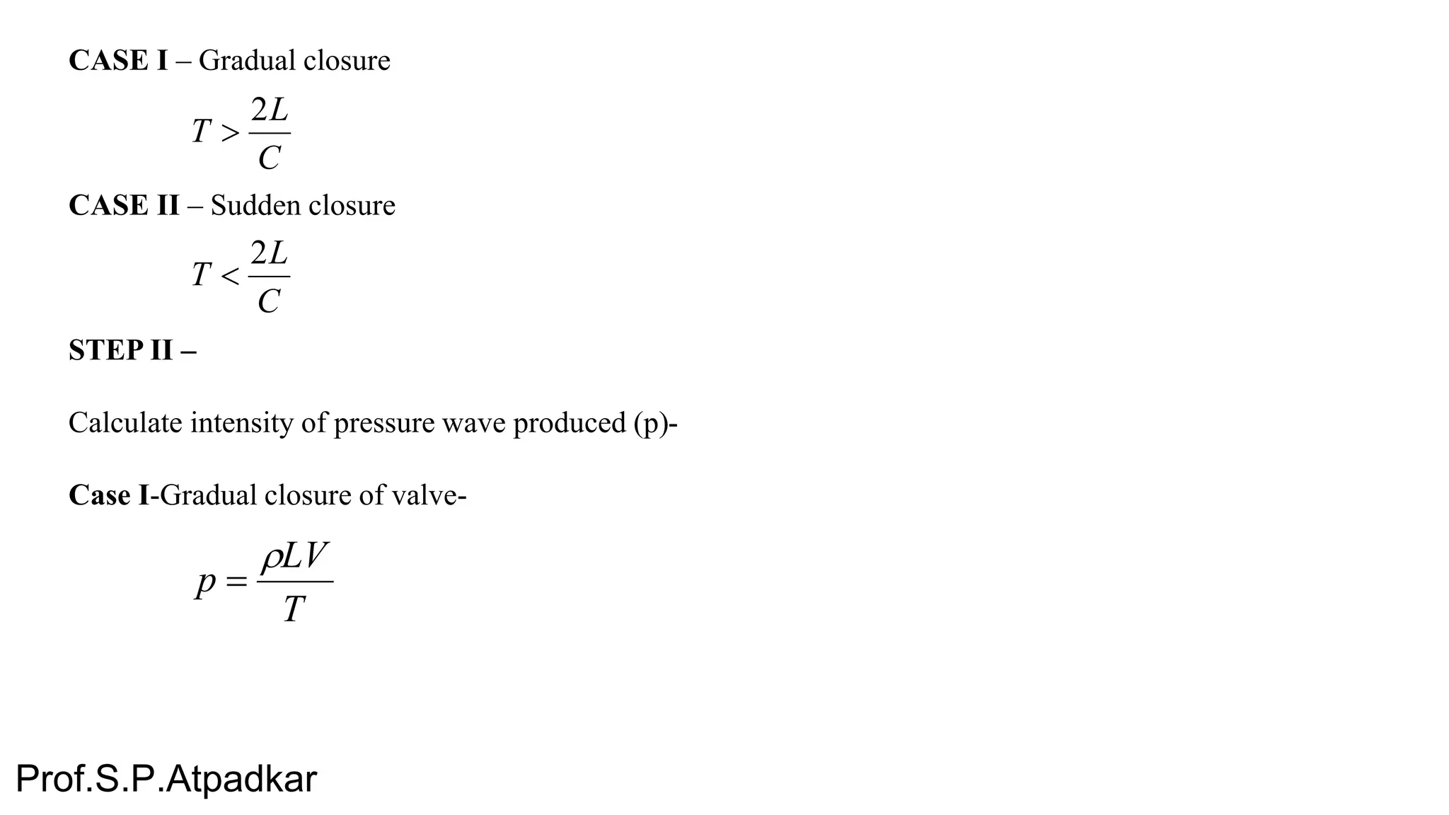


This document outlines the syllabus for an 8th semester BE Civil course in Hydropower Engineering. It includes information about assignments, marking schemes, and term work details. The course focuses on design aspects of hydropower structures like turbines, surge tanks, and draft tubes. 8 assignments are listed related to electricity bill calculation, run-of-river plant design, pumped storage economics, turbine design, surge tank design, water hammer pressure calculation software, and a site visit report. Formulae and steps for designing components like Pelton turbine and conical draft tube are also provided.


