Downloaded 79 times

![Copyright © 2012 Altair Engineering, Inc. Proprietary and Confidential. All rights reserved.
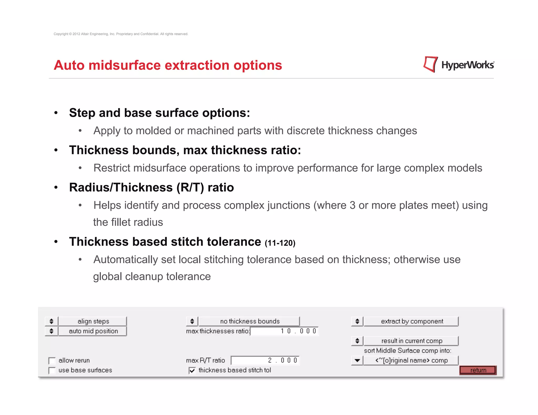
Auto midsurface extraction options
• Extract by component / cross components
• By component: each original part is it’s own component; extract midsurface one
part at a time
• Cross components: original part geometry consists of multiple components
• Result in Middle Surface component / current component
• Sorting options:
• Specifies how to organize middle surfaces when using the sort function:
• <~[o]riginal name> comp
• <Midsurface #nn> comp
• original comp](https://image.slidesharecdn.com/htc2012midsurfacingtraining-120622073534-phpapp01/75/HTC-2012-Midsurfacing-Training-7-2048.jpg)
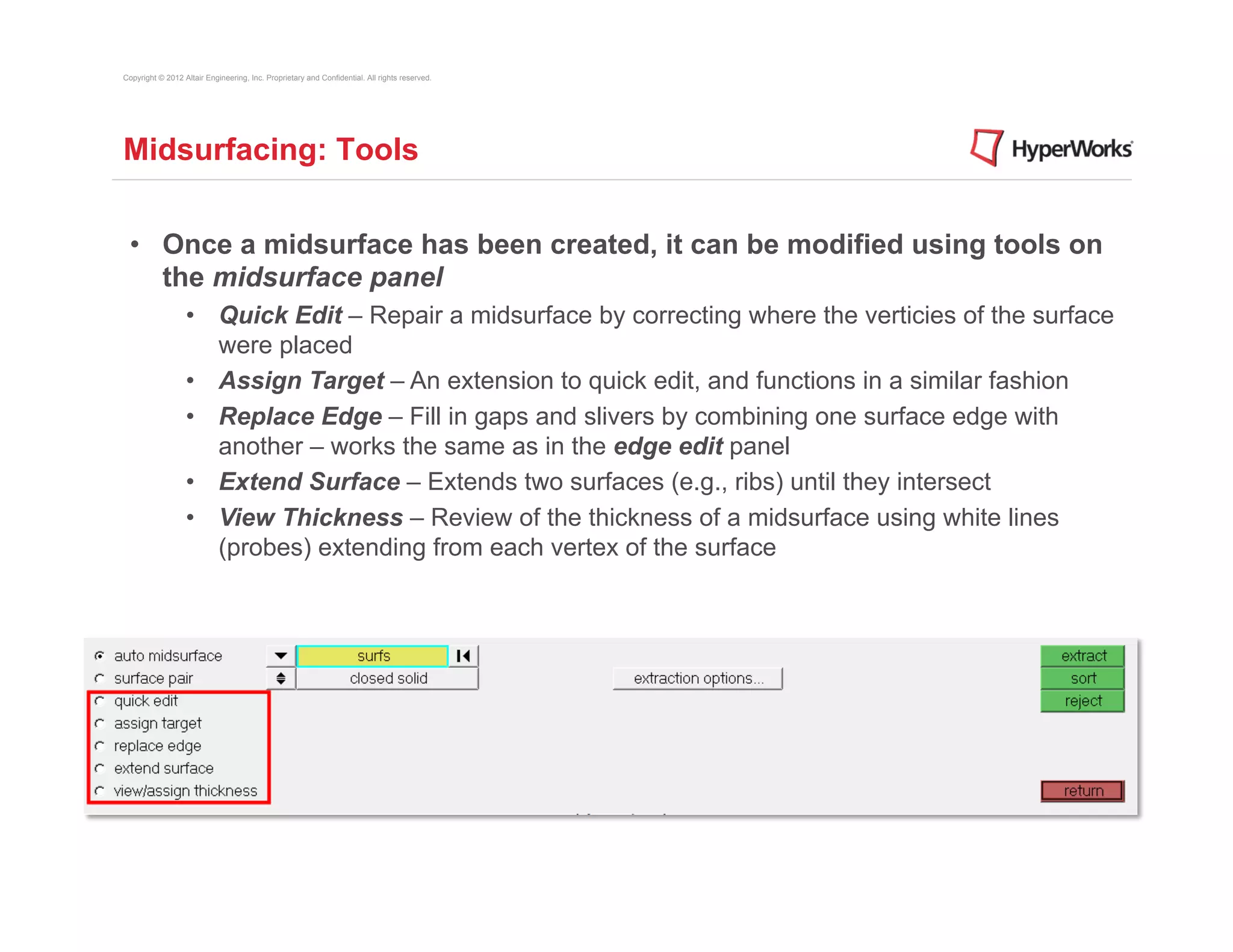
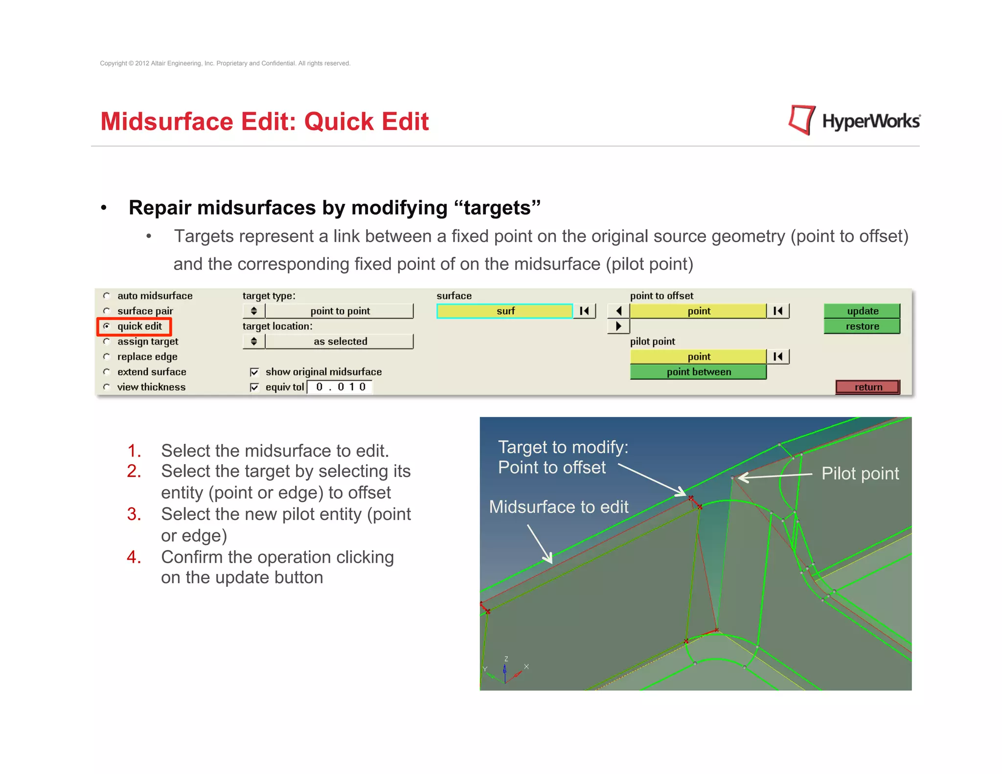
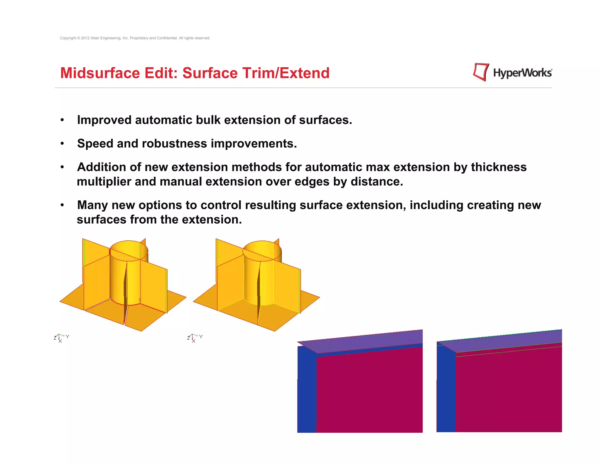

The document discusses tools in HyperMesh for generating mid-surfaces from 3D geometry to simplify models. It describes: 1) Automatically generating mid-surfaces representing the center plane of thin parts like sheet metal or plastic parts, while keeping the original geometry. 2) Options for controlling the automatic extraction process, like defining thickness bounds or stitching tolerances. 3) Tools for editing mid-surfaces like quick edit to adjust target points, extending surfaces to intersect, and viewing surface thicknesses.


