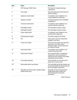
HPE Synergy 12000 Frame Setup and
Installation Guide
Part Number: 806424-002
Published: August 2017
Edition: 2
Abstract
This document describes identification, installation, and setup for the HPE Synergy System.
This guide is for an experienced service technician. Hewlett Packard Enterprise assumes you
are qualified in the servicing of the HPE Synergy components and overall solution.
© Copyright 2016, 2017 Hewlett Packard Enterprise Development LP
Notices
The information contained herein is subject to change without notice. The only warranties for Hewlett
Packard Enterprise products and services are set forth in the express warranty statements accompanying
such products and services. Nothing herein should be construed as constituting an additional warranty.
Hewlett Packard Enterprise shall not be liable for technical or editorial errors or omissions contained
herein.
Confidential computer software. Valid license from Hewlett Packard Enterprise required for possession,
use, or copying. Consistent with FAR 12.211 and 12.212, Commercial Computer Software, Computer
Software Documentation, and Technical Data for Commercial Items are licensed to the U.S. Government
under vendor's standard commercial license.
Links to third-party websites take you outside the Hewlett Packard Enterprise website. Hewlett Packard
Enterprise has no control over and is not responsible for information outside the Hewlett Packard
Enterprise website.
Acknowledgments
Microsoft®
and Windows®
are either registered trademarks or trademarks of Microsoft Corporation in the
United States and/or other countries.
Contents
Planning the installation.........................................................................6
Safety and regulatory compliance.................................................................................................6
Site requirements..........................................................................................................................6
Determine power and cooling configurations................................................................................6
Power supply calculations..................................................................................................6
Power requirements...........................................................................................................6
Warning, caution, and important messages..................................................................................7
Space and airflow requirements................................................................................................... 8
Temperature requirements............................................................................................................9
Grounding requirements............................................................................................................... 9
Supported racks and rack options................................................................................................ 9
Rack-free environment requirements...............................................................................10
Pallet contents............................................................................................................................ 10
Component and LED identification..................................................... 13
Information pull tabs....................................................................................................................13
Mobile-ready content........................................................................................................14
Mobile QR code locations................................................................................................ 14
Frame front components and device bays..................................................................................14
Device bay numbering..................................................................................................... 15
Front panel components.................................................................................................. 17
Appliance module LEDs and components....................................................................... 19
Frame rear components..............................................................................................................21
Rear component bay numbering......................................................................................21
Frame link module components and LEDs...................................................................... 22
Power supply LED............................................................................................................24
Fan LED...........................................................................................................................24
Installation............................................................................................. 26
Installing the Synergy system components.................................................................................26
Removing components from the frame ......................................................................................26
Installing the frame in a rack-free environment...........................................................................27
Installing the frame in a rack.......................................................................................................27
Measuring with the rack template.................................................................................... 28
Installing the rack rails for a square-hole rack..................................................................28
Installing the rack rails for a round-hole rack................................................................... 30
Installing the frame into the rack ..................................................................................... 30
Component installation............................................................................................................... 33
Installing an appliance module.........................................................................................34
Installing compute modules .............................................................................................35
Installing the storage module........................................................................................... 42
Installing fans................................................................................................................... 42
Installing power supplies..................................................................................................43
Installing a Frame Link Module ....................................................................................... 46
Installing interconnect modules........................................................................................46
Cabling the frame........................................................................................................................52
Contents 3
Cabling...................................................................................................54
Network cabling...........................................................................................................................54
Frame link module cabling............................................................................................... 54
Interconnect module cabling............................................................................................ 56
Remote management ring cabling for inclusion into HPE OneView................................ 64
Connect to the HPE Synergy Console........................................................................................64
Connecting to the HPE Synergy Console using a keyboard, video monitor, and
mouse...............................................................................................................................64
Connecting to the HPE Synergy Console using a laptop computer.................................65
Power cabling............................................................................................................................. 66
Cabling power supplies for power feed redundancy........................................................ 66
Cabling multiple frames for power feed redundant power................................................67
Configuring HPE Synergy.................................................................... 69
Configuring the frame overview.................................................................................................. 69
Synergy Console Frame Health & Inventory screen........................................................ 69
Verifying installation using HPE OneView...................................................................................71
Configure HPE Synergy Image Streamer................................................................................... 72
Configuring HPE OneView to deploy OS build artifacts to compute modules..................73
Troubleshooting....................................................................................74
Error screens when connecting to the Synergy console.............................................................74
Synergy Composer not responding..................................................................................74
Frame not claimed by a Synergy Composer....................................................................75
Synergy console cannot connect to HPE OneView......................................................... 76
Synergy console icons..................................................................................................... 77
Issues during installation.............................................................................................................80
HPE Synergy console.................................................................................................................81
Accessing the HPE OneView maintenance console from the frame link module............ 81
Connecting to the HPE OneView maintenance console using SSH................................ 82
Creating a support dump file............................................................................................82
Resetting to factory settings........................................................................................................83
Resetting the appliance to the original factory settings....................................................83
Performing a frame link module factory reset.................................................................. 84
Documentation and troubleshooting resources for HPE Synergy...85
HPE Synergy documentation......................................................................................................85
HPE Synergy Configuration and Compatibility Guide...................................................... 85
HPE Synergy Frame Link Module User Guide.................................................................85
HPE OneView User Guide for HPE Synergy................................................................... 85
HPE OneView Global Dashboard.................................................................................... 85
HPE Synergy Image Streamer User Guide......................................................................85
HPE Synergy Image Streamer GitHub.............................................................................86
HPE Synergy Software Overview Guide..........................................................................86
HPE Synergy Firmware Update Overview....................................................................... 86
Best Practices for HPE Synergy Firmware and Driver Updates...................................... 86
HPE OneView Support Matrix for HPE Synergy.............................................................. 86
HPE Synergy Image Streamer Support Matrix................................................................ 86
HPE Synergy Glossary.....................................................................................................86
HPE Synergy troubleshooting resources....................................................................................86
Troubleshooting within HPE OneView............................................................................. 87
4 Contents
HPE Synergy Troubleshooting Guide.............................................................................. 87
Error Message Guide for HPE ProLiant Gen10 servers and HPE Synergy.....................87
HPE OneView Help, HPE OneView REST API Scripting Help, and HPE OneView
API Reference..................................................................................................................87
HPE Synergy QuickSpecs................................................................................................87
HPE Synergy document overview (documentation map)................. 88
Specifications........................................................................................89
HPE Synergy QuickSpecs.......................................................................................................... 89
Electrostatic discharge.........................................................................90
Support and other resources...............................................................91
Accessing Hewlett Packard Enterprise Support......................................................................... 91
Accessing updates......................................................................................................................91
Customer self repair....................................................................................................................92
Remote support.......................................................................................................................... 92
Warranty information...................................................................................................................92
Regulatory information................................................................................................................93
Documentation feedback............................................................................................................ 93
Acronyms and abbreviations...............................................................94
Contents 5
Planning the installation
Safety and regulatory compliance
For important safety, environmental, and regulatory information, see Safety and Compliance Information
for Server, Storage, Power, Networking, and Rack Products, available at the Hewlett Packard Enterprise
website (http://www.hpe.com/support/Safety-Compliance-EnterpriseProducts).
Site requirements
Select an installation site that meets the detailed installation site requirements described in the site
planning guide on the Hewlett Packard Enterprise website (http://www.hpe.com/info/synergy-docs).
Determine power and cooling configurations
Validate power and cooling requirements based on location and installed components.
For more information, see the HPE Synergy Configuration and Compatibility Guide on the Hewlett
Packard Enterprise website (http://www.hpe.com/info/synergy-docs).
Power supply calculations
For hot-plug power supply specifications, see the HPE Synergy QuickSpecs on the Hewlett Packard
Enterprise website (http://www.hpe.com/info/synergy-docs). There is also the Synergy Planning Tool
for download. The Synergy Planning Tool helps plan and organize all Synergy options to build a single
frame, multiple frame, or racks for a complete solution ready to order from HPE using a simple BOM from
the tool. The Synergy Planning Tool can be found on the Hewlett Packard Enterprise Sales Portal website
in the Tools section.
Power requirements
Installation of this equipment must comply with local and regional electrical regulations governing the
installation of IT equipment by licensed electricians. This equipment is designed to operate in installations
covered by NFPA 70, 1999 Edition (National Electric Code) and NFPA-75, 1992 (code for Protection of
Electronic Computer/Data Processing Equipment). For electrical power ratings on options, refer to the
product rating label or the user documentation supplied with that option.
WARNING:
To reduce the risk of personal injury, fire, or damage to the equipment, do not overload the AC
supply branch circuit that provides power to the rack. Consult the electrical authority having
jurisdiction over wiring and installation requirements of your facility.
CAUTION:
Protect the storage module from power fluctuations and temporary interruptions with a regulating
UPS. This device protects the hardware from damage caused by power surges and voltage spikes
and keeps the storage module in operation during a power failure.
6 Planning the installation
Warning, caution, and important messages
WARNING:
To reduce the risk of personal injury or damage to equipment, heed all warnings and cautions
throughout the installation instructions.
WARNING:
To reduce the risk of personal injury or damage to the equipment, be sure that:
• The leveling feet are extended to the floor.
• The full weight of the rack rests on the leveling feet.
• The stabilizing feet are attached to the rack if it is a single-rack installation.
• The racks are coupled together in multiple-rack installations.
• Only one component is extended at a time. A rack may become unstable if more than one
component is extended for any reason.
WARNING:
The frame is very heavy. To reduce the risk of personal injury or damage to the equipment:
• Observe local occupational health and safety requirements and guidelines for manual material
handling.
• Remove all installed components from the frame before installing or moving the frame.
• Use caution and get help to lift and stabilize the frame during installation or removal, especially
when the frame is not fastened to the rack.
WARNING:
Always use at least four people to lift the frame into the rack. If the frame is being loaded into the
rack above chest level, a fifth person must assist with aligning the frame with the rails while the
other four people support the weight of the frame.
WARNING:
Install the frame starting from the bottom of the rack and work your way up the rack.
These symbols, on power supplies or systems, indicate that the equipment is supplied
by multiple sources of power.
NOTE:
To reduce the risk of injury from electric shock, remove all power cords to
completely disconnect power from the system.
• Each frame has two or more power supply cords. A single rack or cabinet
may contain more than one frame. Power may be supplied in a redundant
fashion. Removing any single source of power does not necessarily remove
power from any portion of the system. When performing any service other
than hot-plug module replacement, you must completely disconnect all
power to that portion of the system.
• When performing service procedures on frames, shut off the circuit breakers
to both A and B AC power feeds and then disconnect all power cords from
the outlets before servicing.
Warning, caution, and important messages 7
WARNING:
To reduce the risk of electric shock or damage to the equipment, enter a frame or perform service
on system components only as instructed in the user documentation.
WARNING:
A risk of electric shock from high leakage current exists. Before connecting the AC supply to the
power enclosure, be sure that the electrical outlets are properly grounded (earthed).
CAUTION:
Always be sure that equipment is properly grounded and that you follow proper grounding
procedures before beginning any installation procedure. Improper grounding can result in ESD
damage to electronic components. For more information, see "Electrostatic discharge."
CAUTION:
Protect the storage module from power fluctuations and temporary interruptions with a regulating
UPS. This device protects the hardware from damage caused by power surges and voltage spikes
and keeps the storage module in operation during a power failure.
Space and airflow requirements
CAUTION:
In high-density configurations, the HPE 11000 G2 Series Rack Airflow Optimization Kit (BW930A)
should be installed to prevent airflow from the rear of the rack to the front the rack via gaps in the
rack frame.
To enable servicing and ensure adequate airflow, observe the following spatial requirements when
deciding where to install a Hewlett Packard Enterprise-branded, Compaq-branded, Telco, or third-party
rack:
• Leave a minimum clearance of 63.5 cm (25 in) in front of the rack.
• Leave a minimum clearance of 76.2 cm (30 in) in back of the rack.
• Leave a minimum clearance of 121.9 cm (48 in) from the back of the rack to the rear of another rack or
row of racks.
Compute modules draw cool air in through the front and expel warm air through the rear of the frame.
Therefore, the front of the frame must be adequately ventilated to enable ambient room air to enter the
frame, and the rear of the frame must be adequately ventilated to enable the warm air to escape from the
frame.
Hewlett Packard Enterprise Advanced Series Racks, Hewlett Packard Enterprise Series Racks, and
Hewlett Packard Enterprise Standard Series Racks provide proper compute module cooling through flow-
through perforations in the front and rear doors that provide 65 percent open area for ventilation.
If the front of the rack is not completely filled with components, the remaining gaps between the
components can cause changes in the airflow, which can adversely affect cooling within the rack. Cover
these gaps with blanking panels.
IMPORTANT:
Do not block the ventilation openings.
8 Space and airflow requirements
CAUTION:
Always use blanking panels to fill empty vertical spaces in the rack. This arrangement ensures
proper airflow. Using a rack without blanking panels results in improper cooling that can lead to
thermal damage.
Temperature requirements
To ensure continued safe and reliable equipment operation, install or position the rack in a well-ventilated,
climate-controlled environment.
The operating temperature inside the rack is always higher than the room temperature and is dependent
on the configuration of equipment in the rack. Check the TMRA for each piece of equipment before
installation.
CAUTION:
To reduce the risk of damage to the equipment when installing third-party options:
• Do not permit optional equipment to impede airflow around the frame or to increase the internal
rack temperature beyond the maximum allowable limits.
• Do not exceed the manufacturer’s TMRA.
Grounding requirements
This equipment must be grounded properly for proper operation and safety. In the United States, you
must install the equipment in accordance with NFPA 70, 1999 Edition (National Electric Code), Article
250, as well as any local and regional building codes.
In Canada, you must install the equipment in accordance with Canadian Standards Association, CSA
C22.1, Canadian Electrical Code.
In all other countries, you must install the equipment in accordance with any regional or national electrical
wiring codes, such as the International Electrotechnical Commission (IEC) Code 364, parts 1 through 7.
Furthermore, you must be sure that all power distribution devices used in the installation, such as branch
wiring and receptacles, are listed or certified grounding-type devices.
Because of the high ground-leakage currents associated with this equipment, Hewlett Packard Enterprise
recommends the use of a PDU that is either permanently wired to the building’s branch circuit or includes
a nondetachable cord that is wired to an industrial-style plug. NEMA locking-style plugs or those
complying with IEC 60309 are considered suitable for this purpose. Using common power outlet strips to
supply power to this equipment is not recommended.
Supported racks and rack options
The frame and support rails are engineered for mounting into a 19" wide front panel, 4-post cabinets, and
racks that have been designed according to the EIA-310-D standard.
Hewlett Packard Enterprise rails are not compatible with tapped holes. There are two types of supported
rail sets for the frame:
• A set for square-hole front and rear mounting flanges
• A set for round-hole flanges
The rails are compatible with a nominal rack-mounting depth of 29 1/8", with an adjustability range of plus
½" to minus 1 ½". The rails will work in both a 1075 mm and a 1200 mm deep rack.
A 42U/47U rack supports up to four frames.
Temperature requirements 9
While the square-hole rail set is the standard option, either rail set supports a fully loaded frame weighing
550 pounds. Four of these frames together approach the 2,250 pound internal IT equipment limit of both
the HPE 42U x 600 mm x 1075 mm and the 42U 600 mm x 1200 mm 11000G2 Series QS racks.
NOTE: The HPE Synergy 12000 Frame is deeper than the c7000 enclosure by approximately 3.5
inches. 1075 racks with side facing PDUs may interfere with the frame. Hewlett Packard Enterprise
recommends using 1200 mm racks.
Cables, PDUs, and other cable management hardware could increase the weight sufficiently to require
the use of the HPE 42U x 600 mm x 1200 mm Intelligent Series QS rack, which supports 2,750 pound
internal IT equipment.
Rack-free environment requirements
The HPE Synergy 12000 Frame (referred to as the frame) can be used in a rack-free environment. The
following conditions must be met when performing a rack-free installation:
• A fully-populated frame can weigh up to 249.50 kg kg ( 550.00 lb lb). The object supporting the frame
must be able to withstand this weight.
• The frame should be supported by a sturdy, flat surface.
WARNING:
To reduce the risk of personal injury or damage to the equipment in a rack-free environment:
◦ Never stack the frame on top of another frame.
◦ Never place equipment on top of the frame.
◦ Never place the frame on a surface that cannot support up to 249.50 kg kg ( 550.00 lb lb).
Pallet contents
10 Rack-free environment requirements
Item Name Description
1 HPE Synergy 12000 Frame The frame for installing Synergy
components
2 Front panel The front panel ports of the frame for
KVM connection
3 Appliance module blank A mandatory insert installed in any
unused appliance module bay.
4 Appliance module1 A hardware appliance for embedded
management
5 Compute module blank A mandatory insert installed in any
unused compute module bay.
6 Full-height module1 The full-height compute module
7 Half-height module1 The half-height compute module
8 Power supply blank A mandatory insert installed in any
unused power supply bay
9 Hot-plug power supply1 The power supply for the frame
10 Fan A fan used to cool the components
installed in the frame
11 Frame link module1 The frame link module auto-discovers
resources in the frame, has a
redundant option, and provides links
for scaling of frames.
12 Interconnect blank A mandatory insert installed in any
unused interconnect bay
13 Interconnect module2 Any of several fabric or networking
components, such as switches or
interconnect link modules, that enable
networking communication.
143 Lift handles (optional) The lift handles can be used to lift a
frame into or out of a rack.
153 Removable device bay shelves The removable device bay shelves can
be used to partition the device bays for
full or half-height components
163 Reusable zip ties for power supplies (single-
phase frames only)
Reusable zip ties that help prevent
single-phase power cables from
disconnecting from the power
connectors
Table Continued
Planning the installation 11
Item Name Description
173 CAT6A cable1
CAT6A cable for cabling frames
• 2-ft cable—Used for cabling two
consecutive frames
• 10-ft cable—Used for cabling the
top frame to the bottom frame in a
rack
• 21-ft cable—Used for cabling
management links requiring long
runs to TOR
183 HPE Synergy Start Here poster The quick setup poster provides an
overview of the installation process.
193 Installation instructions for compute modules,
options, and interconnects
The printed installation instructions for
Synergy components
203 HPE Synergy 12000 Frame Rack Template The printed template for locating the
positions of frames, rack rails, and
cage nuts in a rack.
1 Quantity as ordered
2 Quantity and type as ordered
3 Not shown
12 Planning the installation
Component and LED identification
Information pull tabs
Pull tabs on the HPE Synergy frame front and rear provide system information.
Figure 1: Information pull tab locations
Item Description
1 The front pull tab (top left) has the frame product ID, serial number, and the device bay
numbering for the frame front bays.
2 The rear pull tab (top left) has the bay numbering for the frame rear bays.
3 The serial label pull tab is on each compute module and provides the following
information:
• Product serial number
• iLO information
• QR code that points to mobile-friendly documentation
Component and LED identification 13
Figure 2: Accessing the information pull tabs
Mobile-ready content
The HPE Synergy 12000 Frame includes QR codes that point directly to the mobile-ready documentation
from your mobile device.
To access the mobile-ready content, such as setup, installation, user, or troubleshooting documentation,
use your mobile device to scan the product-specific QR code.
Mobile QR code locations
Mobile QR codes are located on HPE Synergy components and pull tabs and provide quick and efficient
access to product specific content for the component. The QR codes takes you to a page that allows you
to browse to the online documentation by choosing an HPE Synergy component.
Frame front components and device bays
14 Mobile-ready content
Item Description
1 Device bays—Compute modules and storage modules
2 Front panel—Provides access to the HPE Synergy console, via KVM or laptop.
3 Appliance bays
Device bay numbering
All device bays in the frame are numbered in consecutive order from lowest to highest, from left to right
from top to bottom, as observed by a user looking directly at the frame.
Devices larger than half-height (multi-bay devices) are numbered according to the lowest device bay
number that the multi-bay device occupies.
For an even number of device modules, they must be installed next to each other between sets of vertical
partitions if all device bays in the frame are to be used.
For an odd number of single-wide full-height device modules, an even number must be installed next to
each other between each vertical partition, and the odd module must be installed in device bay 2 if all
device bays in the frame are to be used.
The device bay numbering is available on the Information pull tabs.
Device bay type Device bay numbering
Single-wide, full-height
Single-wide, half-height
Single-wide, mixed-height
Double-wide, full-height
Double-wide, half-height
Double-wide, mixed-height
Device bay numbering 15
Device bay partitions
Vertical frame partitions
There are two vertical partitions between device bays in the frame. These nonremovable partitions
provide structural integrity to the frame as well as mechanical attach points for the horizontal shelf that
divide a full-height bay into two half-height bays.
Up to six full-height device modules can be installed in a frame.
Figure 3: Vertical partitions
Horizontal frame partitions
The horizontal frame partitions are removable shelves that divide a full-height device bay into a half-
height device bay.
Up to 12 half-height device modules can be installed in a frame.
Figure 4: Horizontal partitions
An optional horizontal half shelf can be installed between bay 1 and bay 7 to enable those bays to be
used by half-height device modules when a full-height module is installed in bay 2.
16 Device bay partitions
Figure 5: Optional horizontal half-shelf
Front panel components
Front panel components 17
Item Description Function
1 UID button Press the frame UID button to toggle the frame UID on or off.
2 Health LED • Solid green—Normal operation
• Flashing amber—Warning Connect to HPE OneView
Hardware Setup to troubleshoot.
• Flashing red—Critical Connect to HPE OneView Hardware
Setup to troubleshoot.
The frame Health LED provides the highest severity status
for all components within the frame. If the frame Health LED
indicates a warning or critical status, connect to the Synergy
console to troubleshoot.
3 Laptop Port RJ-45 Ethernet 100BASE-TX with the following functionality:
• Use a laptop to connect to the Synergy console.
• Configure Laptop Ethernet port for DHCP and enable auto-
negotiation.
• Connect Laptop Ethernet jack to Laptop port with CAT5
cable and check that the laptop received an IP address and
gateway on that port.
• Configure VNC application to connect to the gateway IP
address using port 5900, and then connect to the Synergy
console.
4 Monitor port A connector used for connecting a monitor device or an active
monitor port adapter.
5 Reset Using an applicator such as a paper clip, press the recessed
button to reset the Frame Link Module.
• Press and release—Resets the active Frame Link Module,
and forces a failover if two Frame Link Modules are installed
in the frame.
• Press and hold until UID flashes blue—Factory resets the
Frame Link Modules in the frame.
6 USB USB 2.0 connector used for connecting supported USB devices
such as a keyboard or mouse for Synergy console use. To
connect multiple devices, a USB hub (not included) is required.
18 Component and LED identification
Appliance module LEDs and components
Item Description Function
1 UID LED Press the UID button to turn on the blue locater LED.
• Solid blue—Illuminates to locate the appliance module
• Flashing blue—Indicates appliance module firmware
update. Do not power off or remove appliance module when
the UID LED is flashing.
2 Health LED Indicates the health of the appliance module
• Solid green—Normal operation
• Flashing amber—Warning
• Flashing red—Critical error
The appliance Health LED provides health status of the
appliance. If the Health LED indicate a warning or a critical
error, connect to the Synergy console to troubleshoot.
3 Activity LED Indicates which appliance module is active
• Off—Indicates that the appliance module is the standby in a
Highly Available configuration or HPE OneView is in an error
state.
• Solid green—Indicates that the appliance module is active.
• Flashing green—Indicates that the reset button has been
pressed and held for greater than 10 seconds, which
initiates a reimaging of the appliance module. The active
LED does not continue to flash green during the reimaging
process.
Table Continued
Appliance module LEDs and components 19
Item Description Function
4 Power LED Indicates power to the appliance
• Off—No power. Verify that the appliance module is fully
inserted into the Frame Link Module.
• Flashing amber—Appliance module is initializing.
• Solid amber—Appliance module is powered off.
• Solid green—Appliance module is powered on.
5 Reset button Using an applicator such as a paper clip, press the recessed
button to reset the appliance module.
• Press and release—Resets the appliance module.
• Press and hold until activity LED is flashing green—Initiates
reimaging of the appliance module from files on the USB
flash drive plugged into the appliance module.
6 USB port USB 3.0 port for connecting a USB drive to flash a USB
recovery image.
Appliance bay numbering
20 Appliance bay numbering
Frame rear components
Item Description
1 Fans (10)
2 Interconnect modules (up to 6)
3 Power supplies (6)
4 Frame link modules (2)
Rear component bay numbering
Frame rear components 21
Components Bays Labels
Frame link modules 1 and 2
Interconnect modules
These interconnect modules are redundant pairs on fabric 1.
1 and 4
Interconnect modules
These interconnect modules are redundant pairs on fabric 2.
2 and 5
Interconnect modules
These interconnect modules are redundant pairs on fabric 3.
3 and 6
Fans 1 through 10
Power supplies 1 though 6
NOTE: The arrow direction on each of the power supply icons indicates the recommended power
routing to either A-side or B-side. For more information about A-side and B-side power distribution,
see "Power cabling."
Frame link module components and LEDs
22 Frame link module components and LEDs
Item Description Function
1 MGMT port activity
LED
Reports MGMT port activity:
• Flashing green = Activity on the MGMT port
• Off = No activity on the MGMT port
2 MGMT port A 10GBASE-T 1 RJ45 connector that provides two functions:
• Provides a management uplink to the management network.
• Provides a data connection to the data network when an Image
Streamer management appliance is installed in the frame.
3 MGMT port
connectivity LED
Reports MGMT port connectivity:
• Solid green = MGMT port is connected.
• Off = MGMT port is not connected.
4 Health LED Provides the health status of the Frame Link Module.
• Solid green—Normal operation
• Flashing amber—Warning
• Flashing red—Critical error
If the Health LED indicates a warning or a critical error, connect to
the HPE OneView Hardware Setup or HPE Synergy Console to
troubleshoot.
5 UID button Toggles the UID LED on or off.
• Solid blue = Activated
• Off = Deactivated
• Flashing blue = Firmware upgrade is in progress on the Frame Link
Module.
Neither Frame Link Module should be removed while the UID LED is
flashing.
6 USB Allows connection to the frame using a supported USB devices such as
a keyboard or mouse for HPE Synergy console use. To connect
multiple devices, a USB hub (not included) is required.
7 LINK port activity LED Reports LINK port activity:
• Flashing green = Activity on the LINK port
• Off = No activity on the LINK port
8 LINK port A 10GBASE-T 1 RJ45 connector that provides two functions:
• Provides linking to a LINK port on another Frame Link Module to
provide high availability management network connectivity for two
Frame Link Modules in a single frame.
• Provides links to multiple frames for automatic discovery by the HPE
Synergy Composer appliance module.
Table Continued
Component and LED identification 23
Item Description Function
9 LINK port connectivity
LED
Reports LINK port connectivity:
• Solid green = LINK port is connected.
• Off = LINK port is not connected.
10 Monitor port Allows connection to the frame using a monitor device or an active
monitor port adapter.
1 The 10GBASE-T MGMT port automatically negotiates speed to 10GbE or 1GbE based on the connection.
Power supply LED
Power LED Condition
Off No input power to the power supply or power supply failure. Connect to
the HPE Synergy console and check for power supply error messages.
Solid green Normal operation
Flashing amber Warning. Connect to HPE OneView Hardware Setup to troubleshoot.
Fan LED
24 Power supply LED
LED color Fan status
Solid green Normal operation
Flashing red Critical. Connect to HPE OneView Hardware Setup to troubleshoot.
Component and LED identification 25
Installation
Installing the Synergy system components
Procedure
1. Unpack the system.
2. Remove components from the frame.
3. For rack-free installations, set up the frame on an appropriate surface, and then install the frame
options.
4. For rack installations, install the frame into the rack, and then install the frame options.
5. Install the frame components into the frame.
6. Connect the frame components in the frame.
7. Connect the AC power cables and power up the frame.
8. Configure the frame using the Composer.
Removing components from the frame
Before installing the frame into the rack, you must remove all of the pre-installed components from the
front and rear of the frame. Since a fully-populated frame can weigh up to 249.50 kg kg ( 550.00 lb lb),
removing the components from the frame makes moving and installing the frame easier.
With the frame still on the pallet, remove all components from the front and rear of the frame.
IMPORTANT:
To ensure the correct configuration when installing components, be sure to note the location of each
component before removing it from the frame.
26 Installation
For specific instructions concerning removing the components, see the HPE Synergy 12000 Frame
Maintenance and Service Guide.
Installing the frame in a rack-free environment
WARNING:
To reduce the risk of personal injury or damage to the equipment in a rack-free environment:
• Never stack the frame on top of another frame.
• Never place equipment on top of the frame.
• Never place the frame on a surface that cannot support up to 249.50 kg kg ( 550.00 lb lb).
Procedure
1. Select the location for the frame. For more information, see "Rack-free environment requirements."
2. Remove components from the frame.
3. Place the frame on a flat, sturdy surface to support the frame.
4. Complete the component installation for your configuration.
Installing the frame in a rack
CAUTION:
Always plan the rack installation so that the heaviest item is on the bottom of the rack. Install the
heaviest item first, and continue to populate the rack from the bottom to the top.
NOTE: Up to four 10U frames can be installed in a 42U rack. If you are installing more than one
frame, install the first frame in the bottom of the rack, and then install additional frames by moving
up the rack with each subsequent frame. Plan rack installation carefully because it is difficult to
change the location of components after they are installed.
Procedure
1. Remove components from the frame.
2. Use the rack template to mark the locations for the rack rails.
3. Install the rack rails and cage nuts for each frame.
Installing the frame in a rack-free environment 27
For more information, see the appropriate section according to the type of rack being used.
4. Install the frame into the rack.
5. Complete the component installation for your configuration.
Measuring with the rack template
The HP Synergy 12000 Frame Rack Template ships with the frame and provides detailed instructions on
where to position the frame and rack rails, and where to install the cage or clip nuts. Each frame kit
includes the rack rails recommended for that frame.
NOTE: Four cage nuts and four clip nuts are included with the frame. Cage nuts should be used in
racks with square holes. Clip nuts should be used in racks with round holes.
When installing multiple frames, install the rack rails and cage nuts for one frame, and then install the
frame. Repeat for each additional frame.
Procedure
1. Install lower cage nuts (left and right) in the front of the rack at the bottom of the fourth U (10 holes up
on the template).
2. Install the upper cage nuts (left and right) in the front of the rack at the bottom of the tenth U (28 holes
up on the template).
3. Install the rack rails.
Installing the rack rails for a square-hole rack
Rack rails are marked "LEFT" and "RIGHT" for identification. The rail release levers are used only when
removing the rail from the rack.
Procedure
1. Begin with the left rack rail. Shorten the rail.
28 Measuring with the rack template
2. Align the rear end of the rail with the rack rear column.
3. Position the rail tabs next to the square openings in the rack rear column.
4. Keeping the rail level, insert the rear rail tabs into the rack rear column, and push the tabs down into
place.
5. Extend the front of the rack rail to the rack front column.
6. Position the rail tabs next to the square openings in the rack front column.
7. Insert the front rail tabs into the rack front column and push the tabs down into place.
Installation 29
8. Repeat the procedure for the right rack rail.
The installation is complete.
Installing the rack rails for a round-hole rack
Procedure
1. Align and install the rails in the rack.
2. Repeat the procedure for the other rail.
To remove the rails, reverse the installation procedure.
Installing the frame into the rack
WARNING:
Always use at least four people to lift a frame into the rack. If the frame is being loaded into the rack
above chest level, a fifth person must assist with aligning the frame with the rails while the other four
people support the weight of the frame.
30 Installing the rack rails for a round-hole rack
NOTE: You can install the frame into the rack using a mechanical lift. If you choose the mechanical
lift installation, resume the frame installation at step 5.
Procedure
1. Attach the lift handles to the frame.
a. Align each lift handle to the frame spools.
b. Press the release button, and then pull the lift handle up until it locks in place.
2. Line up the frame with the rack, set the back end of the frame on the rack rails and slide it in.
3. Slide the frame into the rack until the rear lift handles are close to the rack. While still supporting the
frame with the front lift handles, remove the rear lift handles from each side of the frame, and then
slide the frame halfway into the rack.
Installation 31
4. Slide the frame into the rack until the front lift handles are close to the rack. Remove the front lift
handles from each side of the frame, and then slide the frame fully into the rack.
5. Remove the left and right frame bezels from front of the frame by inserting your finger in the hole at
the bottom of the frame bezel and pull out and up, then pull the top of the frame bezel away from the
frame.
32 Installation
6. Tighten the thumbscrews with a T-25 Torx screwdriver to secure the frame to the rack.
7. Repeat the procedure for the remaining frames.
NOTE: Up to four 10U frames can be installed in a 42U rack. If you are installing more than one
frame, install the first frame in the bottom of the rack, and then install additional frames by
moving up the rack with each subsequent frame. Plan rack installation carefully because it is
difficult to change the location of components after they are installed.
Component installation
The following sections contain installation instructions for the individual frame components. The images
included in these instructions are intended to illustrate how the components are installed. These images
are not intended to indicate the location for installation. Install the component in the bay from which it was
removed earlier in this document.
There is no specific installation order requirement for the frame components, however Hewlett Packard
Enterprise recommends installing all front components first, followed by all rear components.
All components must be installed and cabled before you power up the frame.
Component installation 33
The frame and components automatically power on when power is connected.
Installing an appliance module
The appliance modules have specific population guidelines based on the appliance module and the
system configuration. As a best practice, if there are two of the same type of appliance modules in any
group of linked frames for redundancy or high availability, install them in separate frames.
Procedure
1. Remove the appliance module blank from the appliance bay.
a. Press the upper latch.
b. Pull the blank or appliance module out of the frame.
2. Insert the first Composer into appliance bay 1. When the Composer is fully inserted, it locks into place.
3. After the Composer appliance is installed in the frame, verify the latest HPE OneView or HPE Image
Streamer versions are downloaded from the Hewlett Packard Enterprise Update Center and are
installed on the Composer.
34 Installing an appliance module
a. Connect to the appliance using the Synergy console.
b. Select the serial icon on the top bar and select the appliance bay.
c. Log into the appliance as maintenance to see the appliance firmware version.
Installing compute modules
Depending on the compute modules for your frame:
• Install device bay partitions
• Install a full-height compute module
• Install a half-height compute module
Installing a full-height compute module
The HPE Synergy 12000 Frame ships with three device bay shelves installed to support a 12 half-height
compute module configuration. To install a full-height compute module, remove the device bay shelves
and corresponding blanks.
Procedure
1. Remove the blanks.
2. Remove the device bay shelf.
NOTE: Keep the compute module end caps, blanks, and device bay shelves for future use.
3. Remove the compute module end cap.
Installing compute modules 35
4. Prepare the compute module for installation.
5. Prepare the compute module for installation by opening the compute module handle.
6. Install the compute module. Press the compute module handle near each release button to completely
close the handle.
36 Installation
CAUTION:
To prevent improper cooling and thermal damage, do not operate the compute module or the
frame unless all device bays are populated with either a component or a blank.
7. Install blanks in any empty bays.
Removing a device bay shelf
Procedure
1. Press and hold the release latches to release the locking mechanism.
2. Slide the removable shelf out of the frame.
Creating a full-height module bay blank
Procedure
1. Obtain the coupler plate:
Installation 37
• If you are using a module bay blank that came with the frame, the coupler plate can be found with
the contents of the full-height device shipping box.
• If you are using a device bay blank that you purchased as an option, remove the coupler plate from
inside the blank.
2. Fit the coupler plate into the slots on top of the blank, and then slide the coupler plate back until it
snaps into place.
3. Fit the slots on the bottom of the second blank on to the coupler plate tabs, and then slide the second
blank forward until it snaps in place.
4. Install the full-height blank into the device bay.
Installing a half-height compute module
Procedure
1. Remove the blank.
38 Installing a half-height compute module
2. If required, install the device bay shelf.
NOTE: Keep the compute module end caps, blanks, and device bay shelves for future use.
3. Remove the compute module end cap.
4. Prepare the compute module for installation by opening the compute module handle.
Installation 39
5. Install the compute module. Press the compute module handle near the release button to completely
close the handle.
Installing a device bay shelf
The frame has a slot and notch on the device bay walls that is used to guide the shelf when inserted.
Procedure
1. Locate the slot and notch shelf guides.
40 Installation
2. Press and hold the latches of the removable shelf and insert into the device bay using the shelf
guides.
3. Once fully inserted, release the latches to lock in place.
Installation 41
Installing the storage module
Procedure
1. Prepare the storage module for installation by pressing down on the storage module handle release
latch, which opens the storage module handle.
NOTE: The storage module handle arrives packaged in the closed position and must be opened
prior to inserting into the frame.
2. Install a storage module by sliding it into the frame. Push the storage module handle to the closed
position until it clicks into place.
3. Press the driver drawer release latch and pull out the drawer with the driver drawer release handle.
4. Install a replacement/new drive, and then close the drive drawer.
Installing fans
All ten fans must be populated at all times. There is no required installation order for installing the fans.
42 Installing the storage module
To install a fan, insert the fan into the frame until it locks into place.
CAUTION:
Use caution to avoid hitting the PCA card edge against the frame. Damage to the fan PCA could
result in malfunction of the fan or the frame.
After power is applied to the frame, verify each fan LED is green.
Installing power supplies
WARNING:
To reduce the risk of personal injury from hot surfaces, allow the power supply or power supply
blank to cool before touching it.
WARNING:
To reduce the risk of electric shock or damage to the equipment, do not connect the power cord to
the power supply until the power supply is installed.
Procedure
1. Remove the power supply blank, or unplug the power cord and remove the power supply from the
frame.
2. Remove the output connector cover from the new power supply.
Installing power supplies 43
3. Insert the power supply into the frame until it locks into place. The power supply is marked with TOP to
ensure proper orientation during installation.
4. Connect the power cord to the power supply.
5. Secure the power cord using the reusable zip tie attached to the power supply.
44 Installation
6. Connect the power cord to the power source.
7. Check the power supply LEDs to determine the status of the power supply.
Power supply configurations
Sufficient power supplies must be installed to support the installed devices and interconnect modules. For
power specifications and calculators to determine electrical and heat loading for HPE Synergy, see the
HPE Synergy Planning Tool on the HPE Synergy Sales Portal.
NOTE: Contact your local authorized Hewlett Packard Enterprise account representative to access
the Synergy Sales Portal.
The number of supported power supplies in the frame range from a minimum of two to a maximum of six
power supplies. There are no restrictions to the placement of any number of power supplies in the frame
at any location, however for best cooling and power distribution, Hewlett Packard Enterprise recommends
the following best practice supply usage.
NOTE: The default power mode is Redundant power feed mode.
Number of power
supplies
Power modes Power supply bay (Power feed)
1 Not supported —
2 Redundant power supply mode
Redundant power feed mode
1(A) and 3(A)
1(A) and 3(B)
3 1 Redundant power supply mode 1(A), 3(A), and 5(A)
4 Redundant power supply mode
Redundant power feed mode
1(A), 3(A), 4(A), and 6(A)
1(A), 3(B), 4(A), and 6(B)
5 1
Redundant power supply mode 1(A), 2(A), 3(A), 4(A), and 6(A)
6 Redundant power supply mode
Redundant power feed mode
1(A), 2(A), 3(A), 4(A), 5(A), and 6(A)
1(A), 2(A), 3(B), 4(A), 5(B), and 6(B)
Power supply configurations 45
1 If an odd number of power supplies are installed in a frame that is configured for redundant power feed mode, all
power supplies are providing power to the frame, but the capacity of the odd power supply is not used to determine
the overall power capacity of the frame.
To enhance cooling, power supply blanks must be installed in all empty bays for any configuration that
does not require power supplies in all six power supply bays.
Power supply configuration rules for the frame do not depend on the type of power supply being used,
however all power supplies must be of the same type. Mixed-type power supply configurations are not
supported.
Installing a Frame Link Module
Procedure
1. If installed, remove the Frame Link Module blank from the rear of the frame.
CAUTION:
Use caution when installing the Frame Link Module into the frame to avoid damage to the
connector. Installing a Frame Link Module with a damaged connector can result in damage to the
midplane.
2. Remove the Frame Link Module end cap.
3. Insert the Frame Link Module into the frame.
4. Close the Frame Link Module latch.
Installing interconnect modules
There are six single-wide interconnect bays in the frame. Installation in the interconnect bays depends on
the type of mezzanine card installed in the compute module and in which mezzanine slot the mezzanine
card was installed.
IMPORTANT:
If the mezzanine card is not installed properly or the interconnect module installation does not
coincide with the mezzanine card installation, the ports on the interconnect module will not function.
NOTE: For more information on how and where to install mezzanine cards, see the compute
module user guide or the system configuration guide.
46 Installing a Frame Link Module
Procedure
1. Review the interconnect mapping before selecting the ICM bay to install the interconnect module.
2. If installed, remove the interconnect blank.
3. Remove the interconnect module end cap.
4. Install the interconnect module, and close the release lever.
Installation 47
Interconnect module configurations
The HPE Synergy 12000 Frame supports a pair of redundant interconnect modules for each of the three
fabrics. Hewlett Packard Enterprise recommends the following best practices:
• Fabric 1 primary use—Storage
• Fabric 2 primary use—Storage or networking
• Fabric 3 primary use—Networking
NOTE: Though each fabric has a recommended primary use, it is not required to use the primary
use case. If a fabric is not being used for its primary use, it can still be used for another purpose,
within the allowances.
Fabric Usage ICM description
Fabric 1
ICM Bays 1 and 4
Storage
(Primary)
HPE Synergy 12 Gb SAS Connection Module
Brocade 16 Gb/12 Fibre Channel SAN Switch
Module for HPE Synergy
Brocade 16 Gb/24 Fibre Channel SAN Switch
Module for HPE Synergy
HPE Virtual Connect SE 16 Gb FC Module for
HPE Synergy
Fabric 2
ICM Bays 2 and 5
Storage Brocade 16 Gb/12 Fibre Channel SAN Switch
Module for HPE Synergy
Brocade 16 Gb/24 Fibre Channel SAN Switch
Module for HPE Synergy
HPE Virtual Connect SE 16 Gb FC Module for
HPE Synergy
Table Continued
48 Interconnect module configurations
Fabric Usage ICM description
Fabric 2
ICM Bays 2 and 5
Networking HPE Synergy 40 Gb F8 Switch Module
HPE Virtual Connect SE 40 Gb F8 Module for
HPE Synergy
HPE Synergy 20 Gb Interconnect Link Module
HPE Synergy 10 Gb Interconnect Link Module
HPE Synergy 10Gb Pass-Thru Module
Fabric 3
ICM Bays 3 and 6
Networking
(Primary)
HPE Synergy 40 Gb F8 Switch Module
HPE Virtual Connect SE 40 Gb F8 Module for
HPE Synergy
HPE Synergy 20 Gb Interconnect Link Module
HPE Synergy 10 Gb Interconnect Link Module
HPE Synergy 10Gb Pass-Thru Module
Brocade 16 Gb/12 Fibre Channel SAN Switch
Module for HPE Synergy
Brocade 16 Gb/24 Fibre Channel SAN Switch
Module for HPE Synergy
Always adhere to the following guidelines when planning and installing the interconnect modules in HPE
Synergy frames:
• The interconnect modules are listed in order of priority from top to bottom within a fabric. For example,
if the HPE Synergy 12 Gb SAS Connection module is to be installed, it is only supported in fabric 1
and therefore, that fabric solution is the first priority for fabric 1. If the HPE Synergy 12 Gb SAS
Connection Module is not used, then fabric 1 is available to be used by one of the supported HPE
Synergy Fibre Channel interconnect modules.
• Both ICM bays within a fabric must contain the same interconnect module, unless the fabric is a
Master/Satellite fabric. In a Master/Satellite fabric, one or more satellite modules can be used along
with a master module to form a fabric.
• All interconnect link modules that comprise a Master/Satellite fabric must be installed in the same
interconnect bay number as the corresponding master module. For example, given a three-frame
configuration where the master module is installed in ICM bay 3 in one frame, the two satellite link
modules in the second and third frames must also be installed in ICM bay 3.
Master interconnect module with interconnect link module configurations
The HPE Synergy Virtual Connect SE 40 Gb F8 Module or the HPE Synergy 40Gb F8 Switch Module can
be configured as the master switch, with interconnect link modules to support the master interconnect
module. For the HPE Synergy 10Gb Interconnect Link Module, from one to four interconnect link modules
are required to support the master interconnect module. For the HPE Synergy 20Gb Interconnect Link
Module, from one to two interconnect link modules are required to support the master interconnect
module.
If redundancy is required, then two master switches are required per fabric. For the best availability with
two or more frames, the two switches or VC modules should be installed in different frames.
Installation 49
As an example of a redundant fabric 3 solution, one interconnect module or VC module would be installed
in ICM bay 3 in one frame and the second interconnect module or VC module would be installed in ICM
bay 6 in another frame. ICM bays for the particular fabric that do not contain the interconnect modules or
VC modules would contain the interconnect link modules, providing redundancy for either a interconnect
module failure or frame failure.
Use one interconnect link cable to connect a 10 Gb interconnect link modules to the switch interconnect.
Use two interconnect link cables to connect 20 Gb interconnect link modules to the switch interconnect.
Mezzanine to frame signal routing
The HPE Synergy 12000 Frame midplane provides 4-lane high speed signal routing from all 12 device
bays to the 6 interconnect module bays. A pair of interconnects installed in an interconnect bay set
provide redundant connectivity for each connected mezzanine card. When a device bay contains a
compute module, then each of the installed mezzanine cards connect to the corresponding interconnect
bay sets.
Usage of these interconnections is dependent on the type of fabric chosen to be installed. For example, a
10Gb Ethernet mezzanine card uses only a single lane of each four-lane group. The SAS fabric uses all
four lanes.
Interconnect port mapping
The following compute module device bays map to the interconnect module fabrics. This information is
located on the frame pull tabs.
50 Mezzanine to frame signal routing
The location of a mezzanine option in the compute module dictates the location of the corresponding
interconnect module in the rear of the frame.
Half-height compute module mezzanine connector definitions
NOTE: The compute module hood label includes the exact mezzanine card locations.
Item Mezz slot connector identification Supported card
types
Fabric Interconnect
bay sets
1 Mezzanine slot 1 (M1) Type C and Type D 1 ICM 1 and 4
2 Mezzanine slot 2 (M2)1 Type C and Type D 2 ICM 2 and 5
3 Mezzanine slot 3 (M3) Type C only 3 ICM 3 and 6
1 When installing a mezzanine option in mezzanine slot 2, processor 2 must be installed.
Half-height compute module mezzanine connector definitions 51
Full-height compute module mezzanine connector definitions
NOTE: The compute module hood label includes the exact mezzanine card locations.
The symbols in the image correspond with symbols on the rear of the frame.
Item Mezz slot connector
identification
Supported card
types
Fabric Supported ICM bays
1 Mezzanine slot 1 (M1) Type C and Type D 1 ICM 1 and 4
2 Mezzanine slot 2 (M2)1 Type C and Type D 2 ICM 2 and 5
3 Mezzanine slot 3 (M3) Type C only 3 ICM 3 and 6
4 Mezzanine slot 4 (M4) Type C and Type D 1 ICM 1 and 4
5 Mezzanine slot 5 (M5)1 Type C and Type D 2 ICM 2 and 5
6 Mezzanine slot 6 (M6) Type C 3 ICM 3 and 6
1 When installing a mezzanine option in mezzanine slot 2, processor 3 must be installed. When installing a mezzanine
option in mezzanine slot 5, processor 4 must be installed.
Cabling the frame
WARNING:
To reduce the risk of electric shock or injury due to high-current electrical energy, be sure that all
power is completely disconnected at the source before beginning any power connections to the
power bus bars or power bus box.
WARNING:
Be sure that all circuit breakers are locked in the off position before connecting any power
components.
52 Full-height compute module mezzanine connector definitions
Procedure
1. Connect the power cables. Connect to the power source in your facility to each of the installed power
supplies, and power up the frame.
For more information, see Power cabling on page 66.
2. Connect the network cables.
For more information, see Network cabling on page 54.
3. Connect to the Synergy console.
For more information, see Connect to the HPE Synergy Console on page 64.
Installation 53
Cabling
Network cabling
To ensure the frame and installed components are connected to the network, the following connections
are required:
• Frame link module cabling
• Interconnect module cabling
• Remote management ring cabling for inclusion into HPE OneView
Frame link module cabling
The Frame Link Modules connect each frame together in a management ring that provides a 10 Gb fault
tolerant management connectivity and automatic discovery for HPE Synergy Composer to all linked
components.
IMPORTANT:
The cabling images shown here are example configurations. If your HPE Synergy Composer
appliances are in different locations from the examples, then your cable routing is different.
IMPORTANT:
When an HPE Synergy system has HPE Synergy Image Streamer installed in any of the appliance
bays, the MGMT port cabling will be different. For more information about cabling frame link
modules for HPE Synergy Image Streamer, see the HPE Synergy Configuration and Compatibility
Guide.
1. Cable the Frame Link Modules for a single- frame management ring:
a. Using a minimum of CAT6A patch cable, connect the LINK ports together.
b. Using a minimum of CAT6A patch cable, connect the MGMT port of each of the installed frame link
modules to the management network.
NOTE:
The green arrows indicate the connection to the management network.
54 Cabling
Item Description
1 Frame Link Module (MGMT and LINK ports)
2 HPE Synergy Composer in appliance bay 1
3 HPE Synergy Composer in appliance bay 2
2. Cable the Frame Link Modules for a multi- frame management ring:
a. Using a minimum of CAT6A patch cable, connect the LINK ports on all Frame Link Modules
together in a ring.
b. Using a minimum of CAT6A patch cable, connect the MGMT port of each frame link module to the
external management network if a HPE Synergy Composer is installed in the corresponding
appliance bay.
Hewlett Packard Enterprise recommends connecting the two management uplinks from separate
frames, if possible.
In the example below, the green lines indicate the MGMT connections to the management network.
The MGMT port from the frame link module bay 1 in the top frame and the MGMT port from the
frame link module bay 2 in the bottom frame connect to the management network.
Cabling 55
Item Description
1 Frame Link Module (MGMT and LINK ports)
2 HPE Synergy Composer in frame 1 (top) and appliance bay 1
3 HPE Synergy Composer in frame 3 (bottom) appliance bay 2
For CAT6A cables available for linking frames and connecting to management networks, see the Frame
Link Module section of the HPE Synergy 12000 Frame QuickSpecs on the Hewlett Packard Enterprise
website.
Interconnect module cabling
HPE Synergy supports a composable fabric that spans multiple frames and includes master interconnect
modules (switches) and satellite modules (links). If your HPE Synergy configuration has a composable
fabric, Hewlett Packard Enterprise recommends cabling the HPE Synergy Ethernet interconnect modules
in a master switch configuration, so that multiple interconnect link modules can support the master
interconnect module.
To cable switch modules to interconnect link modules, use the examples that follow or see the installation
instructions provided with the interconnect link module.
Master interconnect module with 10G interconnect link module cabling
1. In a multiframe system, connect either the HPE Synergy 40Gb F8 Switch Module or the HPE Virtual
Connect SE 40Gb F8 Module for HPE Synergy as the master to a satellite HPE Synergy 10Gb
Interconnect Link Module in a different frame.
Using interconnect link cables, connect the L1, L2, L3, or L4 ports on the master to the L1 port on
each satellite.
56 Interconnect module cabling
Figure 6: Cabling the interconnect modules in a five-frame system
2. In a single-frame or multiframe system, connect both masters with two stacking cables:
a. Connect a stacking cable from port Q7 on the first master to port Q7 on the second module.
b. Connect a stacking cable from port Q8 on the first master to port Q8 on the second module.
The examples shown use the HPE Virtual Connect SE 40Gb F8 Module for HPE Synergy. The cabling
varies depending on the modules being stacked.
Cabling 57
Figure 7: Multi-frame stacking example
58 Cabling
Figure 8: Single-frame stacking example
Attribute Value Description
Maximum compute modules 5 Each network is a single physical
switch/hop
Maximum half-height compute
modules
60 Each network has 1:1 OSR
between servers
Satellite links (CXP) per interconnect
module
1 Each switch can connect to four 10
G interconnect link modules
Stacking ports (QSFP+) 4 Can also be used for non-Flex
uplinks
Uplink ports (QSFP+) 12 FlexPorts: 4 x 10G, 1 x 40 G, 4 x
2/4/8G FC
Uplink oversubscription 2.25:1
1.88:1
2.25:1 if using only FlexPort uplinks
1.88:1 if also using non-Flex
stacking ports as uplinks
Maximum stacked switches 8 # of switches (interconnect modules
do not count towards limit)
Table Continued
Cabling 59
Attribute Value Description
Maximum redundant fabrics per frame 3 Redundant fabrics 1, 2, and 3 (A
and B)
Components:1
Number of switches 2
Number of 10 G interconnect modules 8
Number of interconnect link cables 8 Cable lengths allow frames to be in
different racks
Number of QSFP+ stacking cables 2 In this use case, QSFP+ ports are
used for stacking
Number of 10 G mezzanine cards 60 Maximum for 60 compute module
(five frame) deployment
1 Double component counts for two redundant fabrics, and triple component counts for three redundant fabrics.
Master interconnect module with 20G interconnect link module cabling
1. In a multiframe system, connect either the HPE Synergy 40Gb F8 Switch Module or the HPE Virtual
Connect SE 40Gb F8 Module for HPE Synergy as the master to a satellite HPE Synergy 20Gb
Interconnect Link Module in a different frame:
a. Using interconnect link cables, connect one of the L1 and L4 ports on the master to the L1 and L2
ports on one satellite.
b. For a three-frame system, use interconnect link cables to connect the L2 and L3 ports on the same
master to the L1 and L2 ports on the other satellite.
60 Master interconnect module with 20G interconnect link module cabling
Figure 9: Cabling the interconnect modules in a three-frame system
2. In a single-frame or multiframe system, connect both masters with two stacking cables:
a. Connect a stacking cable from port Q7 on the first master to port Q7 on the second module.
b. Connect a stacking cable from port Q8 on the first master to port Q8 on the second module.
The examples shown in this section use the HPE Virtual Connect SE 40Gb F8 Module for HPE
Synergy. The cabling varies depending on the modules being stacked.
Cabling 61
Figure 10: Multiframe stacking example
62 Cabling
Figure 11: Single-frame stacking example
Attribute Value Description
Maximum compute modules 3 Each network is a single physical
switch/hop
Maximum half-height compute
modules
36 Each network has 1:1 OSR
between servers
Satellite links (CXP) per interconnect
module
2 Each switch can connect to two 20
G interconnect link modules
Stacking ports (QSFP+) 4 Can also be used for non-Flex
uplinks
Uplink ports (QSFP+) 12 FlexPorts: 4 x 10G, 1 x 40 G, 4 x
2/4/8G FC
Uplink oversubscription 3:2
3:2
3:2 if using only FlexPort uplinks
3:2 if also using non-Flex stacking
ports as uplinks
Maximum stacked switches 8 # of switches (interconnect modules
do not count towards limit)
Table Continued
Cabling 63
Attribute Value Description
Maximum redundant fabrics per frame 3 Redundant fabrics 1, 2, and 3 (A
and B)
Components:1
Number of switches 2
Number of 20 G interconnect modules 4
Number of interconnect link cables 8 Cable lengths allow frames to be in
different racks
Number of QSFP+ stacking cables 2 In this use case, QSFP+ ports are
used for stacking
Number of 20 G mezzanine cards 36 Maximum for 36 compute module
(two or three frame) deployment
1 Double component counts for two redundant fabrics, and triple component counts for three redundant fabrics
Remote management ring cabling for inclusion into HPE OneView
One or more frames connected in a management ring that does not contain a Composer is referred to as
a remote management ring. Each remote management ring should have a redundant pair of management
uplinks connected to the management network. This connection is made through any two MGMT ports
within the remote management ring, preferably from Frame Link Modules located in separate frames.
A remote management ring is not automatically discovered and claimed by the HPE Synergy Composer.
Remote management rings must be manually imported to HPE OneView. To complete the import, the
IPv6 link-local address of any one of the Frame Link Modules in the remote management ring must be
entered into HPE OneView. The IPv6 link-local address of the remote Frame Link Modules must be set up
to be on the same IPv6 link-local subnet as the management ring where the Composers are located.
Once HPE OneView recognizes the remote Frame Link Module, all the equipment within the remote ring
is claimed by HPE OneView.
Connect to the HPE Synergy Console
You can connect to the HPE Synergy console using a notebook computer or a keyboard, video monitor,
and mouse.
The HPE Synergy console provides access to HPE OneView running on an HPE Synergy Composer
appliance.
The HPE Synergy console also provides access to the serial console for modules installed within a frame,
including management appliances, interconnects, or compute modules. To access the serial console for a
module, connect to the HPE Synergy console via ports in the same frame as the module.
When installing an HPE Synergy system, to access HPE OneView, connect to the HPE Synergy console
via ports in a frame that has an HPE Synergy Composer appliance. After all frames in an HPE Synergy
system have been claimed during hardware setup, you can connect to any frame to access HPE
OneView through the HPE Synergy console.
Connecting to the HPE Synergy Console using a keyboard, video monitor,
and mouse
Procedure
1. Connect a monitor cable to the monitor port and connect a USB cable to the USB port on either:
64 Remote management ring cabling for inclusion into HPE OneView
• The front of the frame—Front panel module
• The rear of the frame—One of the Frame Link Modules
2. Connect a monitor to the frame with the monitor cable.
3. Connect a USB keyboard and mouse to the USB ports on the monitor, and connect the monitor USB
to the frame with the USB cable.
An alternative is to connect the USB keyboard and mouse to a USB hub connected to the frame.
Connecting to the HPE Synergy Console using a laptop computer
NOTE:
Do not plug the front panel laptop port into a switch. The front panel laptop port is designed to
provide access to the HPE Synergy Console using a laptop computer.
Procedure
1. Ensure that the Ethernet port of the laptop computer is configured for DHCP.
Connecting to the HPE Synergy Console using a laptop computer 65
Alternatively, you can configure the laptop Ethernet port to the IP address: 192.168.10.2 with the
subnet 255.255.255.0.
2. Use a CAT5 cable to connect the laptop computer Ethernet port to the laptop port on a front panel
module.
3. Wait for the laptop computer to be assigned an IP address from the Frame Link Module.
4. Access the Synergy Console using either a VNC client or web browser.
a. Web browser: Open a web browser and enter "http://192.168.10.1:5800".
b. VNC client: Open a VNC client and connect to 192.168.10.1 port 5900.
A VNC client will load to the web browser and open the Synergy Console.
Power cabling
The frame can be cabled for power feed redundancy or power supply redundancy.
Cabling power supplies for power feed redundancy
Power feed redundancy may be achieved by connecting 1+1, 2+2, or 3+3 power supplies to Phase A+B.
To cable a frame for power feed redundancy, use the following recommendation as a best practice:
1. Connect power supplies 1, 2, and 4 to the A-side power distribution unit.
2. Connect power supplies 3, 5, and 6 to the B-side power distribution unit.
66 Power cabling
3. Verify that the power supply cords are securely connected using the reusable cable tie wraps.
After power is supplied to the frame, it powers up automatically. The power and health LEDs on the front
panel, Composer appliance, and frame link modules illuminate green to indicate that there are no errors
or alert conditions.
Cabling multiple frames for power feed redundant power
To cable multiple frames for redundancy using best practices, review the following example of a
redundant power feed configuration.
Your configuration can vary depending on the PDUs installed.
Cabling multiple frames for power feed redundant power 67
Figure 12: Multiframe redundant power feed configuration
68 Cabling
Configuring HPE Synergy
Configuring the frame overview
Procedure
1. Verify the component installation is complete.
Review the component health on the Synergy Console Frame Health & Inventory screen.
2. Verify the frame is cabled.
For more information, see "Cabling the frame on page 52."
To test management port connections in the a ring, perform a MGMT Port Test. For more information,
see the HPE Synergy Frame Link Module User Guide at http://www.hpe.com/info/synergy-docs.
3. Verify the frame is powered up.
4. Connect to HPE OneView through the HPE Synergy console.
To access the Synergy console, you must connect locally to a frame with a Composer installed. For
more information, see "Connect to the HPE Synergy Console on page 64."
5. Use HPE OneView to verify the hardware installation.
For more information, see "Verifying installation using HPE OneView on page 71."
6. Complete the hardware setup in HPE OneView.
Synergy Console Frame Health & Inventory screen
The Frame Health & Inventory screen displays the health status of all components in a frame.
Configuring HPE Synergy 69
Figure 13: Frame Health & Inventory screen
Item Description
1 Navigation menu - Breadcrumb navigation menu.
2 Frame health status - Provides the overall frame status.
Statuses include: OK, Warning, and Critical.
3 Frame information - Provides a detailed frame information
including real-time power and temperature readings.
4 Frame link module port information - Provides port states for
the MGMT and LINK ports of each frame link module in the
enclosure.
5 Frame rear view - Displays the health status of components
installed in the rear of the frame. Each component can be
clicked to see individual component health and information
screens.
6 Frame front view - Displays the health status of components
installed in the front of the frame. Each component can be
clicked to see individual component health and information
screens.
Table Continued
70 Configuring HPE Synergy
Item Description
7 Actions menu - Provides access to frame link module
management actions, serial connections to appliance modules
and interconnects, and access to computer module iLO
Integrated Remote Consoles.
8 Help screen - Provides information on the system icons and
the HPE Synergy Console license agreement.
Verifying installation using HPE OneView
Procedure
1. From the Synergy console, click Connect to start HPE OneView.
2. To connect with install technician user privileges, click Hardware Setup.
3. Review the hardware inventory.
a.
NOTE: A spinning icon at the top of the inventory section indicates when HPE OneView is
bringing the enclosures and the devices within them under management. Devices might not
be listed until the discovery process is complete.
Wait for HPE OneView to complete the add operation.
b. Confirm that the inventory includes all installed components.
c. For any hardware not discovered by HPE OneView, look for problems with Frame Link Module
cabling, hardware not fully inserted, or other hardware issues.
4. Review and correct any issues listed in the Hardware Setup Checklist.
a. To troubleshoot all issues, follow corrective actions in HPE OneView.
b. Return to the Hardware Setup screen and check for additional issues until the Checklist indicates
Setup complete.
Verifying installation using HPE OneView 71
For more information about using HPE OneView, see the online help by clicking the question mark on
the top bar of the Synergy console.
5. (Optional) Select Edit networking from the Hardware Setup screen.
Edit the HPE OneView networking settings and click OK. The Maintenance IP address fields are
required unless you have disabled service console access.
6. To add a remote enclosure, select Actions > Add remote enclosures from the Hardware Setup
screen.
Enter the IPv6 address of a frame link module that is connected to a frame in the remote frame link
topology. The remote frame link topology must be in the same subnet as the primary frame link
topology.
7. Unmanaged interconnect modules require console access for initial setup. Click the Actions menu on
the top bar of the Synergy console and select the module from the Serial Consoles > Interconnects
menu. Press the Enter key to begin the serial console session with that interconnect module.
Configure the interconnect module using the instructions provided with the module. To close the
session, click the X in the top right corner.
NOTE: To access the serial console for an interconnect module, connect to the Synergy console
through ports in the same frame as the module. For more information, see the procedures for
connecting to the Synergy console.
8. Log out from the HPE OneView Hardware Setup session.
To close the session, click the X in the top right corner of the Synergy console.
After hardware setup is complete, the system is ready to be configured for a production environment.
An HPE OneView administrator can perform configuration tasks with an account that provides
additional user privileges.
For more information about HPE OneView administration, see the HPE OneView online help or the
HPE OneView User Guide for Synergy.
For operating system deployment options on HPE Synergy, see the HPE Synergy 12000 Frame Setup
and Installation Guide.
Configure HPE Synergy Image Streamer
HPE Synergy Image Streamer can be used to deploy OS build artifacts to the Synergy compute modules.
However, it must be installed and configured within HPE OneView.
Procedure
1. Create a management network that is consistent with the HPE OneView management network.
2. Add an IPv4 subnet and address range.
Define the range of IPv4 addresses and subnets to set aside for each Image Streamer appliance in
the frame link topology, plus the number of operating system servers expected to be deployed.
3. Add an OS deployment server for use in HPE OneView to deploy operating systems to managed
servers.
4. Create a deployment network to enable operating system deployment to servers using Image
Streamer.
5. Create one or more logical interconnect groups to define the connections between Image Streamer
appliances and the servers they will support.
6. Create an enclosure group that includes the Image Streamer configuration.
7. Create a logical enclosure to define the set of frames to which to apply the Image Streamer enclosure
group.
72 Configure HPE Synergy Image Streamer
For more information about configuring HPE Image Streamer, see the HPE OneView online help or the
HPE OneView User Guide on the Hewlett Packard Enterprise website (http://www.hpe.com/info/
synergy-docs).
Configuring HPE OneView to deploy OS build artifacts to compute modules
Once you add an Image Streamer OS deployment server in HPE OneView, you can launch the Image
Streamer graphical user interface from the HPE OneView OS Deployment Servers screen.
Procedure
1. Upload artifacts from a bundle or create new artifacts.
From the Image Streamer interface, the software administrator can upload artifacts from a bundle for
use in HPE OneView or use the Image Streamer interface to create golden images and other OS build
artifacts.
2. Create or configure a server profile.
Create and apply a server profile which includes an OS deployment selection and values for the
server-specific settings for the selected OS deployment.
3. Verify operating system deployment.
Review server profile screen details to view the operating system volume that has been created as a
result of deployment.
4. Power on the compute module.
Power on server to boot from deployed operating system.
For more information about using Image Streamer to create and deploy OS build artifacts, see the Image
Streamer online help or the HPE Image Streamer User Guide on the Hewlett Packard Enterprise website
(http://www.hpe.com/info/synergy-docs).
Configuring HPE OneView to deploy OS build artifacts to compute modules 73
Troubleshooting
Error screens when connecting to the Synergy console
The following are some basic errors screens that may be encountered when connecting to the Synergy
console.
Synergy Composer not responding
If the frame Composers are detected but not responding after 20 minutes, the following Attention screen
appears, and prompts a Reset.
Select Reset. HPE OneView resets and attempts again to boot the frame Composers.
74 Troubleshooting
Frame not claimed by a Synergy Composer
When the frame is not claimed by a Synergy Composer, the following Attention screen appears.
To resolve, connect to the front panel display of a frame that contains a Synergy Composer.
Frame not claimed by a Synergy Composer 75
Synergy console cannot connect to HPE OneView
If the Synergy console cannot connect to HPE OneView, the following Attention screen appears.
76 Synergy console cannot connect to HPE OneView
If you are unable to connect to HPE OneView, perform the following troubleshooting solutions.
Procedure
1. Connect to the Synergy console through a different frame.
2. Reconnect to HPE OneView.
3. Verify there are no more than three live HPE OneView sessions within the management network. Any
initiated sessions after three will not be able to connect to HPE OneView.
Synergy console also has icons available for further navigation. For more information, see "Synergy
console icons."
Synergy console icons
The icons in the top right help to navigate.
• Question Mark icon - Select this icon to access the basic Synergy console help screen.
• i icon - Select this icon to access the Information screen. The local frame information, including
firmware version and discovered hardware components within the frame are displayed.
Synergy console icons 77
• Screen icon - Select this icon to access the hardware components discovered by the Synergy
console, including Appliances, Interconnects, and Devices. Empty bays are represented by the grayed
out "--" symbol, and components that are discovered but not managed by a serial port are grayed out
and disabled.
78 Troubleshooting
• Serial console - To access the serial console:
1. Select one of the hardware components from the Screen icon to access the serial console for that
component.
Troubleshooting 79
2. Press Enter or another key on the keyboard to activate the console, if needed. Once activated, the
console will begin to display data for the hardware component.
• Keyboard shortcuts - These include:
Keyboard shortcut Action
F10 Show or hide the top caption bar
Ctrl + Zoom in
Ctrl - Zoom out
Ctrl = Zoom default settings
Ctrl Insert Copy selected text
Shift Insert Paste selected text
Issues during installation
During the hardware setup, any installation errors are returned on the final checklist. See the following
image as an example:
• —Indicates a critical error that must be corrected.
• —Indicates a warning that can be corrected, but is not mandatory. For hardware issues, this
warning could mean that redundancy has been lost and additional failures would cause a loss of
service.
80 Issues during installation
To correct the errors that appear, select the hyperlink to the right of the suggested corrective action, and
then follow any additional steps suggested on the screen.
For additional troubleshooting, see "Maintenance console for appliance modules" or
"Troubleshooting within HPE OneView."
HPE Synergy console
The HPE Synergy console is available from a direct connection to the frame if the HPE OneView user
interface cannot be accessed. The functions available in the console might require specific user
credentials.
The HPE Synergy console provides users the ability to troubleshoot issues within the frame and complete
regular maintenance on the installed appliances. From the HPE Synergy console, you can:
• View appliance details
• Restart or shutdown an appliance
• Activate an offline appliance.
• Create a support dump file.
• Reset the appliance password.
• Factory reset the appliance.
• Launch service console.
For more information about the HPE Synergy console, see the HPE Synergy 12000 Frame Maintenance
and Service Guide or the HPE OneView User Guide on the Hewlett Packard Enterprise website.
Accessing the HPE OneView maintenance console from the frame link
module
HPE Synergy console 81
Procedure
1. Connect locally to the HPE Synergy console.
2. Select the Screen icon at the top right of the page.
3. Select an HPE Synergy Composer appliance from the Appliances menu.
A blank text window appears.
4. Press Enter.
5. At the login prompt, log in using the username: maintenance.
The HPE OneView maintenance console opens.
For additional instructions on using the HPE OneView maintenance console, see the HPE OneView User
Guide for HPE Synergy on the Hewlett Packard Enterprise website.
Connecting to the HPE OneView maintenance console using SSH
NOTE: Hewlett Packard Enterprise recommends the use of these tools for accessing the HPE
OneView maintenance console through an SSH connection:
• PuTTY
• MTPuTTY
• vSphere/vCenter Console (HPE BladeSystem c7000)
• Hyper-V console (HPE BladeSystem c7000)
Access the appliance console using this procedure:
Procedure
1. Open one of the recommended tools on your local computer.
2. Access the appliance by specifying its fully qualified domain name or its IP address.
3. Enter the user name maintenance at the login prompt.
4. Log in to the HPE OneView maintenance console.
5. Provide the local administrator credentials when prompted.
Creating a support dump file
This procedure describes how to use the HPE Synergy maintenance console to create a support dump
file from the local appliance (the appliance on which the HPE Synergy maintenance console runs) and
store it on a USB drive.
If the local appliance is the active appliance in an appliance cluster and if the standby appliance is
reachable, the support dump contains the data for both cluster members. Otherwise, a support dump is
created with data for the local appliance only.
The support dump file is encrypted by default.
CAUTION:
Creating the support dump file overwrites any existing backup file on the appliance. If possible,
refrain from creating a support dump if you have not copied the backup file to an external location
for safekeeping.
Prerequisites
• Minimum required privileges: Infrastructure administrator
• Use a USB 2.0 or 3.0 device drive, formatted as an NTFS or FAT32 file system and with only one
partition. If necessary, use a computer to format the USB drive.
• The USB drive must have enough free space (typically 1 GB to 4 GB) to store the support dump file.
82 Connecting to the HPE OneView maintenance console using SSH
Creating a support dump file from the HPE Synergy maintenance console
Procedure
1. Ensure that the USB drive is installed in the USB port of the local appliance.
IMPORTANT:
Do not remove the USB drive until the operation is complete and the Synergy maintenance
console advises that it is safe to remove the drive.
2. Use the appliance console to access the HPE Synergy maintenance console main menu.
3. Select Support dump.
A new set of commands appears.
4. Do one of the following:
• Select Create support dump to create a support dump and copy it to the USB drive.
• Select Download existing support dump to copy a support dump from the appliance to the USB
drive.
5. Wait until the support dump file is copied. There is a message on the screen stating that the support
dump was successfully completed and that it is safe to remove the USB drive.
Resetting to factory settings
In the event that you need to reset settings to their original factory status, the following options are
available:
• Resetting the appliance to the original factory settings on page 83
• Performing a frame link module factory reset on page 84
Resetting the appliance to the original factory settings
A factory reset restores the appliance to the original factory settings. It does not change the installed
firmware version.
You have the option of preserving or erasing the appliance network settings. A factory reset with
preserved network settings is necessary for recovering an HPE Synergy Composer from an
unrecoverable error state. This option clears most faults so that you can restore the appliance from a
backup file.
You might need to reset the appliance either to decommission it (so that you can migrate the hardware) or
to return the appliance to a known state for reuse (for example, to restore the appliance from a backup
file).
CAUTION:
This action erases appliance data including logs. REST API calls and GUI operations are not
allowed during the reset action.
In an appliance cluster, both the active appliance and the standby appliance are reset.
Prerequisites
• Minimum required privileges: Infrastructure administrator
• When resetting or reimaging a Composer to a factory-fresh state, you must also reset all the frames
managed by that Composer to their factory-fresh state. However, if you intend to restore the
Composer settings from a backup after it is reset or reimaged, you do not need to reset all the frames.
Resetting to factory settings 83
IMPORTANT:
To reset the whole system to a factory-fresh state, you must also perform a factory reset on all
the frames in the domain.
If you intend to restore the system from a backup file, you do not need to perform a factory reset
of all the frames. Restoring the system from the backup file restores the frames to management.
• Ensure that all tasks have been completed or stopped, and that all other users are logged off.
Procedure
1. If you are decommissioning the appliance and its managed environment, remove all hardware from
HPE OneView management, for example:
• Delete or un-assign all server profiles.
• Delete all logical enclosures.
• Delete any storage volumes allocated within HPE OneView.
• Reset managed devices (configured through IP address pools) to default IP addressing
2. From the main menu, select Settings ,and then click Appliance.
3. Select Actions > Factory Reset.
4. Select the appropriate option:
• Reset to factory defaults while preserving appliance network settings—Use this option to erase the
appliance data without losing network connectivity, for example, for rebuilding the appliance.
• Full appliance factory reset to defaults—Use this option to prepare a system when returning or
discarding appliance hardware, or when completely reusing a new appliance with new
communication settings.
IMPORTANT:
This option can cause you to lose your network connection to the appliance. Therefore, you
must access the appliance using its IPv6 link local address.
This action displays a progress bar while it is running. Logins are disabled automatically. When the
appliance reset is completed after several minutes, you can log in and set up your appliance as you
did for the first time.
Performing a frame link module factory reset
NOTE:
This procedure only resets the frame link module to factory default settings. It does not reset all the
components in the frame to factory default settings.
NOTE:
Resetting a frame link module to factory default settings will cause a brief disruption in the Synergy
management ring network.
Procedure
1. Log in to the HPE Synergy Console.
2. Select Actions > FLM Diagnostics > Factory Reset.
A progress bar displays.
If the frame link module is installed in a frame managed by HPE OneView, the frame link module will
automatically be claimed by HPE OneView after the factory reset is complete.
84 Performing a frame link module factory reset
Documentation and troubleshooting resources
for HPE Synergy
HPE Synergy documentation
The Hewlett Packard Enterprise Information Library (www.hpe.com/info/synergy-docs) is a task-based
repository. It includes installation instructions, user guides, maintenance and service guides, best
practices, and links to additional resources. Use this website to obtain the latest documentation, including:
• Learning about HPE Synergy technology
• Installing and cabling HPE Synergy
• Updating the HPE Synergy components
• Using and managing HPE Synergy
• Troubleshooting HPE Synergy
HPE Synergy Configuration and Compatibility Guide
The HPE Synergy Configuration and Compatibility Guide is in the Hewlett Packard Enterprise Information
Library (www.hpe.com/info/synergy-docs). It provides an overview of HPE Synergy management and
fabric architecture, detailed hardware component identification and configuration, and cabling examples.
HPE Synergy Frame Link Module User Guide
The HPE Synergy Frame Link Module User Guide is in the Hewlett Packard Enterprise Information
Library (www.hpe.com/info/synergy-docs). It outlines frame link module management, configuration,
and security.
HPE OneView User Guide for HPE Synergy
The HPE OneView User Guide for HPE Synergy is in the Hewlett Packard Enterprise Information Library
(www.hpe.com/info/synergy-docs). It describes resource features, planning tasks, configuration quick
start tasks, navigational tools for the graphical user interface, and more support and reference information
for HPE OneView.
HPE OneView Global Dashboard
The HPE OneView Global Dashboard provides a unified view of health, alerting, and key resources
managed by HPE OneView across multiple platforms and data center sites. The HPE OneView Global
Dashboard User Guide is in the Hewlett Packard Enterprise Information Library (www.hpe.com/info/
synergy-docs). It provides instructions for installing, configuring, navigating, and troubleshooting the
HPE OneView Global Dashboard.
HPE Synergy Image Streamer User Guide
The HPE Synergy Image Streamer User Guide is in the Hewlett Packard Enterprise Information Library
(www.hpe.com/info/synergy-docs). It describes the OS deployment process using Image Streamer,
features of Image Streamer, and purpose and life cycle of Image Streamer artifacts. It also includes
authentication, authorization, and troubleshooting information for Image Streamer.
Documentation and troubleshooting resources for HPE Synergy 85
HPE Synergy Image Streamer GitHub
The HPE Synergy Image Streamer GitHub repository (github.com/HewlettPackard) contains sample
artifacts and documentation on how to use the sample artifacts. It also contains technical white papers
explaining deployment steps that can be performed using Image Streamer.
HPE Synergy Software Overview Guide
The HPE Synergy Software Overview Guide is in the Hewlett Packard Enterprise Information Library
(www.hpe.com/info/synergy-docs). It provides detailed references and overviews of the various
software and configuration utilities to support HPE Synergy. The guide is task-based and covers the
documentation and resources for all supported software and configuration utilities available for:
• HPE Synergy setup and configuration
• OS deployment
• Firmware updates
• Troubleshooting
• Remote support
HPE Synergy Firmware Update Overview
The HPE Synergy Firmware Update Overview is in the Hewlett Packard Enterprise Information Library
(www.hpe.com/info/synergy-docs). It provides information on how to update the firmware for HPE
Synergy.
Best Practices for HPE Synergy Firmware and Driver Updates
The Best Practices for HPE Synergy Firmware and Driver Updates is in the Hewlett Packard Enterprise
Information Library (www.hpe.com/info/synergy-docs). It provides information on recommended best
practices to update firmware and drivers through HPE Synergy Composer, which is powered by HPE
OneView.
HPE OneView Support Matrix for HPE Synergy
The HPE OneView Support Matrix for HPE Synergy is in the Hewlett Packard Enterprise Information
Library (www.hpe.com/info/synergy-docs). It maintains the latest software and firmware requirements,
supported hardware, and configuration maximums for HPE OneView.
HPE Synergy Image Streamer Support Matrix
The HPE Synergy Image Streamer Support Matrix is in the Hewlett Packard Enterprise Information
Library (www.hpe.com/info/synergy-docs). It maintains the latest software and firmware requirements,
supported hardware, and configuration maximums for HPE Synergy Image Streamer.
HPE Synergy Glossary
The HPE Synergy Glossary, in the Hewlett Packard Enterprise Information Library (www.hpe.com/info/
synergy-docs), defines common terminology associated with HPE Synergy.
HPE Synergy troubleshooting resources
HPE Synergy troubleshooting resources are available within HPE OneView and in the Hewlett Packard
Enterprise Information Library (www.hpe.com/info/synergy-docs).
86 HPE Synergy Image Streamer GitHub
Troubleshooting within HPE OneView
HPE OneView graphical user interface includes alert notifications and options for troubleshooting within
HPE OneView. The UI provides multiple views of HPE Synergy components, including colored icons to
indicate resource status and potential problem resolution in messages.
You can also use the Enclosure view and Map view to quickly see the status of all discovered HPE
Synergy hardware.
HPE Synergy Troubleshooting Guide
The HPE Synergy Troubleshooting Guide is in the Hewlett Packard Enterprise Information Library
(www.hpe.com/info/synergy-docs). It provides information for resolving common problems and courses
of action for fault isolation and identification, issue resolution, and maintenance for both HPE Synergy
hardware and software components.
Error Message Guide for HPE ProLiant Gen10 servers and HPE Synergy
The Error Message Guide for HPE ProLiant Gen10 servers and HPE Synergy is in the Hewlett Packard
Enterprise Information Library (www.hpe.com/info/synergy-docs). It provides information for resolving
common problems associated with specific error messages received for both HPE Synergy hardware and
software components.
HPE OneView Help, HPE OneView REST API Scripting Help, and HPE
OneView API Reference
The HPE OneView Help, the HPE OneView REST API Scripting Help, and the HPE OneView API
Reference are readily accessible, embedded online help available within the HPE OneView user
interface. These help files include “Learn more” links to common issues, as well as procedures and
examples to troubleshoot issues within HPE Synergy.
The help files are also available in the Hewlett Packard Enterprise Information Library (www.hpe.com/
info/synergy-docs).
HPE Synergy QuickSpecs
HPE Synergy has system specifications as well as individual product and component specifications. For
complete specification information, see the HPE Synergy and individual HPE Synergy product
QuickSpecs on the Hewlett Packard Enterprise website (www.hpe.com/info/qs).
Troubleshooting within HPE OneView 87
HPE Synergy document overview
(documentation map)
www.hpe.com/info/synergy-docs
Planning
• HPE Synergy 12000 Frame Site Planning
Guide
• HPE Synergy Configuration and
Compatibility Guide
• HPE OneView Support Matrix for HPE
Synergy
• HPE Synergy Image Streamer Support
Matrix
• Setup Overview for HPE Synergy
• HPE Synergy Software Overview Guide
Installing hardware
• HPE Synergy Start Here Poster (included
with frame)
• HPE Synergy 12000 Frame Setup and
Installation Guide
• Rack Rails Installation Instructions for the
HPE Synergy 12000 Frame (included with
frame)
• HPE Synergy 12000 Frame Rack Template
(included with frame)
• Hood labels
• User guides
• HPE Synergy Cabling Interactive Guide
• HPE OneView Help for HPE Synergy —
Hardware setup
Configuring for managing and monitoring
• HPE OneView Help for HPE Synergy
• HPE OneView User Guide for HPE
Synergy
• HPE OneView API Reference for HPE
Synergy
• HPE OneView REST API Scripting Help for
HPE Synergy
• User Guides
Managing
• HPE OneView User Guide for HPE Synergy
• HPE Synergy Image Streamer Help
• HPE Synergy Image Streamer User Guide
• HPE Synergy Image Streamer API Reference
• HPE Synergy Image Streamer deployment workflow
• HPE Synergy Frame Link Module User Guide
Monitoring
• HPE OneView User Guide for HPE Synergy
• HPE OneView Global Dashboard User Guide
Maintaining
• Product maintenance and service guides
• Best Practices for HPE Synergy Firmware and Driver
Updates
• HPE OneView Help for HPE Synergy
• HPE OneView User Guide for HPE Synergy
• HPE Synergy Appliances Maintenance and Service
Guide for HPE Synergy Composer and HPE
Synergy Image Streamer
Troubleshooting
• HPE OneView alert details
• HPE Synergy Troubleshooting Guide
• Error Message Guide for HPE ProLiant Gen10
servers and HPE Synergy
• Integrated Management Log Messages and
Troubleshooting Guide for HPE ProLiant Gen10 and
HPE Synergy
• HPE OneView API Reference for HPE Synergy
• HPE Synergy Image Streamer API Reference
88 HPE Synergy document overview (documentation map)
Specifications
HPE Synergy QuickSpecs
HPE Synergy has system specifications as well as individual product and component specifications. For
complete specification information, see the HPE Synergy and individual HPE Synergy product
QuickSpecs on the Hewlett Packard Enterprise website (www.hpe.com/info/qs).
Specifications 89
Electrostatic discharge
Be aware of the precautions you must follow when setting up the system or handling components. A
discharge of static electricity from a finger or other conductor may damage system boards or other static-
sensitive devices. This type of damage may reduce the life expectancy of the system or component.
To prevent electrostatic damage:
• Avoid hand contact by transporting and storing products in static-safe containers.
• Keep electrostatic-sensitive parts in their containers until they arrive at static-free workstations.
• Place parts on a grounded surface before removing them from their containers.
• Avoid touching pins, leads, or circuitry.
• Always be properly grounded when touching a static-sensitive component or assembly. Use one or
more of the following methods when handling or installing electrostatic-sensitive parts:
◦ Use a wrist strap connected by a ground cord to a grounded workstation or computer chassis. Wrist
straps are flexible straps with a minimum of 1 megohm ±10 percent resistance in the ground cords.
To provide proper ground, wear the strap snug against the skin.
◦ Use heel straps, toe straps, or boot straps at standing workstations. Wear the straps on both feet
when standing on conductive floors or dissipating floor mats.
◦ Use conductive field service tools.
◦ Use a portable field service kit with a folding static-dissipating work mat.
If you do not have any of the suggested equipment for proper grounding, have an authorized reseller
install the part.
For more information on static electricity or assistance with product installation, contact an authorized
reseller.
90 Electrostatic discharge
Support and other resources
Accessing Hewlett Packard Enterprise Support
• For live assistance, go to the Contact Hewlett Packard Enterprise Worldwide website:
http://www.hpe.com/assistance
• To access documentation and support services, go to the Hewlett Packard Enterprise Support Center
website:
http://www.hpe.com/support/hpesc
Information to collect
• Technical support registration number (if applicable)
• Product name, model or version, and serial number
• Operating system name and version
• Firmware version
• Error messages
• Product-specific reports and logs
• Add-on products or components
• Third-party products or components
Accessing updates
• Some software products provide a mechanism for accessing software updates through the product
interface. Review your product documentation to identify the recommended software update method.
• To download product updates:
Hewlett Packard Enterprise Support Center
www.hpe.com/support/hpesc
Hewlett Packard Enterprise Support Center: Software downloads
www.hpe.com/support/downloads
Software Depot
www.hpe.com/support/softwaredepot
• To subscribe to eNewsletters and alerts:
www.hpe.com/support/e-updates
• To view and update your entitlements, and to link your contracts and warranties with your profile, go to
the Hewlett Packard Enterprise Support Center More Information on Access to Support Materials
page:
www.hpe.com/support/AccessToSupportMaterials
IMPORTANT:
Access to some updates might require product entitlement when accessed through the Hewlett
Packard Enterprise Support Center. You must have an HPE Passport set up with relevant
entitlements.
Support and other resources 91
Customer self repair
Hewlett Packard Enterprise customer self repair (CSR) programs allow you to repair your product. If a
CSR part needs to be replaced, it will be shipped directly to you so that you can install it at your
convenience. Some parts do not qualify for CSR. Your Hewlett Packard Enterprise authorized service
provider will determine whether a repair can be accomplished by CSR.
For more information about CSR, contact your local service provider or go to the CSR website:
http://www.hpe.com/support/selfrepair
Remote support
Remote support is available with supported devices as part of your warranty or contractual support
agreement. It provides intelligent event diagnosis, and automatic, secure submission of hardware event
notifications to Hewlett Packard Enterprise, which will initiate a fast and accurate resolution based on your
product's service level. Hewlett Packard Enterprise strongly recommends that you register your device for
remote support.
If your product includes additional remote support details, use search to locate that information.
Remote support and Proactive Care information
HPE Get Connected
www.hpe.com/services/getconnected
HPE Proactive Care services
www.hpe.com/services/proactivecare
HPE Proactive Care service: Supported products list
www.hpe.com/services/proactivecaresupportedproducts
HPE Proactive Care advanced service: Supported products list
www.hpe.com/services/proactivecareadvancedsupportedproducts
Proactive Care customer information
Proactive Care central
www.hpe.com/services/proactivecarecentral
Proactive Care service activation
www.hpe.com/services/proactivecarecentralgetstarted
Warranty information
To view the warranty for your product or to view the Safety and Compliance Information for Server,
Storage, Power, Networking, and Rack Products reference document, go to the Enterprise Safety and
Compliance website:
www.hpe.com/support/Safety-Compliance-EnterpriseProducts
Additional warranty information
HPE ProLiant and x86 Servers and Options
www.hpe.com/support/ProLiantServers-Warranties
HPE Enterprise Servers
www.hpe.com/support/EnterpriseServers-Warranties
HPE Storage Products
www.hpe.com/support/Storage-Warranties
92 Customer self repair
HPE Networking Products
www.hpe.com/support/Networking-Warranties
Regulatory information
To view the regulatory information for your product, view the Safety and Compliance Information for
Server, Storage, Power, Networking, and Rack Products, available at the Hewlett Packard Enterprise
Support Center:
www.hpe.com/support/Safety-Compliance-EnterpriseProducts
Additional regulatory information
Hewlett Packard Enterprise is committed to providing our customers with information about the chemical
substances in our products as needed to comply with legal requirements such as REACH (Regulation EC
No 1907/2006 of the European Parliament and the Council). A chemical information report for this product
can be found at:
www.hpe.com/info/reach
For Hewlett Packard Enterprise product environmental and safety information and compliance data,
including RoHS and REACH, see:
www.hpe.com/info/ecodata
For Hewlett Packard Enterprise environmental information, including company programs, product
recycling, and energy efficiency, see:
www.hpe.com/info/environment
Documentation feedback
Hewlett Packard Enterprise is committed to providing documentation that meets your needs. To help us
improve the documentation, send any errors, suggestions, or comments to Documentation Feedback
(docsfeedback@hpe.com). When submitting your feedback, include the document title, part number,
edition, and publication date located on the front cover of the document. For online help content, include
the product name, product version, help edition, and publication date located on the legal notices page.
Regulatory information 93
Acronyms and abbreviations
CSA
Canadian Standards Association
CSR
Customer Self Repair
DHCP
Dynamic Host Configuration Protocol
ESD
electrostatic discharge
IEC
International Electrotechnical Commission
iLO
Integrated Lights-Out
iLO 4
Integrated Lights-Out 4
iPDU
Intelligent Power Distribution Unit
PCIe
Peripheral Component Interconnect Express
PDU
power distribution unit
RETMA
Radio Electronics Television Manufacturers Association (rack spacing)
RoHS
Restriction of Hazardous Substances
SAS
serial attached SCSI
TMRA
recommended ambient operating temperature
UID
unit identification
UPS
uninterruptible power system
USB
universal serial bus
94 Acronyms and abbreviations

HPE-Synergy-12000-Frame-Setup-and-Installation-Guide.pdf

  • 1.
    HPE Synergy 12000Frame Setup and Installation Guide Part Number: 806424-002 Published: August 2017 Edition: 2 Abstract This document describes identification, installation, and setup for the HPE Synergy System. This guide is for an experienced service technician. Hewlett Packard Enterprise assumes you are qualified in the servicing of the HPE Synergy components and overall solution.
  • 2.
    © Copyright 2016,2017 Hewlett Packard Enterprise Development LP Notices The information contained herein is subject to change without notice. The only warranties for Hewlett Packard Enterprise products and services are set forth in the express warranty statements accompanying such products and services. Nothing herein should be construed as constituting an additional warranty. Hewlett Packard Enterprise shall not be liable for technical or editorial errors or omissions contained herein. Confidential computer software. Valid license from Hewlett Packard Enterprise required for possession, use, or copying. Consistent with FAR 12.211 and 12.212, Commercial Computer Software, Computer Software Documentation, and Technical Data for Commercial Items are licensed to the U.S. Government under vendor's standard commercial license. Links to third-party websites take you outside the Hewlett Packard Enterprise website. Hewlett Packard Enterprise has no control over and is not responsible for information outside the Hewlett Packard Enterprise website. Acknowledgments Microsoft® and Windows® are either registered trademarks or trademarks of Microsoft Corporation in the United States and/or other countries.
  • 3.
    Contents Planning the installation.........................................................................6 Safetyand regulatory compliance.................................................................................................6 Site requirements..........................................................................................................................6 Determine power and cooling configurations................................................................................6 Power supply calculations..................................................................................................6 Power requirements...........................................................................................................6 Warning, caution, and important messages..................................................................................7 Space and airflow requirements................................................................................................... 8 Temperature requirements............................................................................................................9 Grounding requirements............................................................................................................... 9 Supported racks and rack options................................................................................................ 9 Rack-free environment requirements...............................................................................10 Pallet contents............................................................................................................................ 10 Component and LED identification..................................................... 13 Information pull tabs....................................................................................................................13 Mobile-ready content........................................................................................................14 Mobile QR code locations................................................................................................ 14 Frame front components and device bays..................................................................................14 Device bay numbering..................................................................................................... 15 Front panel components.................................................................................................. 17 Appliance module LEDs and components....................................................................... 19 Frame rear components..............................................................................................................21 Rear component bay numbering......................................................................................21 Frame link module components and LEDs...................................................................... 22 Power supply LED............................................................................................................24 Fan LED...........................................................................................................................24 Installation............................................................................................. 26 Installing the Synergy system components.................................................................................26 Removing components from the frame ......................................................................................26 Installing the frame in a rack-free environment...........................................................................27 Installing the frame in a rack.......................................................................................................27 Measuring with the rack template.................................................................................... 28 Installing the rack rails for a square-hole rack..................................................................28 Installing the rack rails for a round-hole rack................................................................... 30 Installing the frame into the rack ..................................................................................... 30 Component installation............................................................................................................... 33 Installing an appliance module.........................................................................................34 Installing compute modules .............................................................................................35 Installing the storage module........................................................................................... 42 Installing fans................................................................................................................... 42 Installing power supplies..................................................................................................43 Installing a Frame Link Module ....................................................................................... 46 Installing interconnect modules........................................................................................46 Cabling the frame........................................................................................................................52 Contents 3
  • 4.
    Cabling...................................................................................................54 Network cabling...........................................................................................................................54 Frame linkmodule cabling............................................................................................... 54 Interconnect module cabling............................................................................................ 56 Remote management ring cabling for inclusion into HPE OneView................................ 64 Connect to the HPE Synergy Console........................................................................................64 Connecting to the HPE Synergy Console using a keyboard, video monitor, and mouse...............................................................................................................................64 Connecting to the HPE Synergy Console using a laptop computer.................................65 Power cabling............................................................................................................................. 66 Cabling power supplies for power feed redundancy........................................................ 66 Cabling multiple frames for power feed redundant power................................................67 Configuring HPE Synergy.................................................................... 69 Configuring the frame overview.................................................................................................. 69 Synergy Console Frame Health & Inventory screen........................................................ 69 Verifying installation using HPE OneView...................................................................................71 Configure HPE Synergy Image Streamer................................................................................... 72 Configuring HPE OneView to deploy OS build artifacts to compute modules..................73 Troubleshooting....................................................................................74 Error screens when connecting to the Synergy console.............................................................74 Synergy Composer not responding..................................................................................74 Frame not claimed by a Synergy Composer....................................................................75 Synergy console cannot connect to HPE OneView......................................................... 76 Synergy console icons..................................................................................................... 77 Issues during installation.............................................................................................................80 HPE Synergy console.................................................................................................................81 Accessing the HPE OneView maintenance console from the frame link module............ 81 Connecting to the HPE OneView maintenance console using SSH................................ 82 Creating a support dump file............................................................................................82 Resetting to factory settings........................................................................................................83 Resetting the appliance to the original factory settings....................................................83 Performing a frame link module factory reset.................................................................. 84 Documentation and troubleshooting resources for HPE Synergy...85 HPE Synergy documentation......................................................................................................85 HPE Synergy Configuration and Compatibility Guide...................................................... 85 HPE Synergy Frame Link Module User Guide.................................................................85 HPE OneView User Guide for HPE Synergy................................................................... 85 HPE OneView Global Dashboard.................................................................................... 85 HPE Synergy Image Streamer User Guide......................................................................85 HPE Synergy Image Streamer GitHub.............................................................................86 HPE Synergy Software Overview Guide..........................................................................86 HPE Synergy Firmware Update Overview....................................................................... 86 Best Practices for HPE Synergy Firmware and Driver Updates...................................... 86 HPE OneView Support Matrix for HPE Synergy.............................................................. 86 HPE Synergy Image Streamer Support Matrix................................................................ 86 HPE Synergy Glossary.....................................................................................................86 HPE Synergy troubleshooting resources....................................................................................86 Troubleshooting within HPE OneView............................................................................. 87 4 Contents
  • 5.
    HPE Synergy TroubleshootingGuide.............................................................................. 87 Error Message Guide for HPE ProLiant Gen10 servers and HPE Synergy.....................87 HPE OneView Help, HPE OneView REST API Scripting Help, and HPE OneView API Reference..................................................................................................................87 HPE Synergy QuickSpecs................................................................................................87 HPE Synergy document overview (documentation map)................. 88 Specifications........................................................................................89 HPE Synergy QuickSpecs.......................................................................................................... 89 Electrostatic discharge.........................................................................90 Support and other resources...............................................................91 Accessing Hewlett Packard Enterprise Support......................................................................... 91 Accessing updates......................................................................................................................91 Customer self repair....................................................................................................................92 Remote support.......................................................................................................................... 92 Warranty information...................................................................................................................92 Regulatory information................................................................................................................93 Documentation feedback............................................................................................................ 93 Acronyms and abbreviations...............................................................94 Contents 5
  • 6.
    Planning the installation Safetyand regulatory compliance For important safety, environmental, and regulatory information, see Safety and Compliance Information for Server, Storage, Power, Networking, and Rack Products, available at the Hewlett Packard Enterprise website (http://www.hpe.com/support/Safety-Compliance-EnterpriseProducts). Site requirements Select an installation site that meets the detailed installation site requirements described in the site planning guide on the Hewlett Packard Enterprise website (http://www.hpe.com/info/synergy-docs). Determine power and cooling configurations Validate power and cooling requirements based on location and installed components. For more information, see the HPE Synergy Configuration and Compatibility Guide on the Hewlett Packard Enterprise website (http://www.hpe.com/info/synergy-docs). Power supply calculations For hot-plug power supply specifications, see the HPE Synergy QuickSpecs on the Hewlett Packard Enterprise website (http://www.hpe.com/info/synergy-docs). There is also the Synergy Planning Tool for download. The Synergy Planning Tool helps plan and organize all Synergy options to build a single frame, multiple frame, or racks for a complete solution ready to order from HPE using a simple BOM from the tool. The Synergy Planning Tool can be found on the Hewlett Packard Enterprise Sales Portal website in the Tools section. Power requirements Installation of this equipment must comply with local and regional electrical regulations governing the installation of IT equipment by licensed electricians. This equipment is designed to operate in installations covered by NFPA 70, 1999 Edition (National Electric Code) and NFPA-75, 1992 (code for Protection of Electronic Computer/Data Processing Equipment). For electrical power ratings on options, refer to the product rating label or the user documentation supplied with that option. WARNING: To reduce the risk of personal injury, fire, or damage to the equipment, do not overload the AC supply branch circuit that provides power to the rack. Consult the electrical authority having jurisdiction over wiring and installation requirements of your facility. CAUTION: Protect the storage module from power fluctuations and temporary interruptions with a regulating UPS. This device protects the hardware from damage caused by power surges and voltage spikes and keeps the storage module in operation during a power failure. 6 Planning the installation
  • 7.
    Warning, caution, andimportant messages WARNING: To reduce the risk of personal injury or damage to equipment, heed all warnings and cautions throughout the installation instructions. WARNING: To reduce the risk of personal injury or damage to the equipment, be sure that: • The leveling feet are extended to the floor. • The full weight of the rack rests on the leveling feet. • The stabilizing feet are attached to the rack if it is a single-rack installation. • The racks are coupled together in multiple-rack installations. • Only one component is extended at a time. A rack may become unstable if more than one component is extended for any reason. WARNING: The frame is very heavy. To reduce the risk of personal injury or damage to the equipment: • Observe local occupational health and safety requirements and guidelines for manual material handling. • Remove all installed components from the frame before installing or moving the frame. • Use caution and get help to lift and stabilize the frame during installation or removal, especially when the frame is not fastened to the rack. WARNING: Always use at least four people to lift the frame into the rack. If the frame is being loaded into the rack above chest level, a fifth person must assist with aligning the frame with the rails while the other four people support the weight of the frame. WARNING: Install the frame starting from the bottom of the rack and work your way up the rack. These symbols, on power supplies or systems, indicate that the equipment is supplied by multiple sources of power. NOTE: To reduce the risk of injury from electric shock, remove all power cords to completely disconnect power from the system. • Each frame has two or more power supply cords. A single rack or cabinet may contain more than one frame. Power may be supplied in a redundant fashion. Removing any single source of power does not necessarily remove power from any portion of the system. When performing any service other than hot-plug module replacement, you must completely disconnect all power to that portion of the system. • When performing service procedures on frames, shut off the circuit breakers to both A and B AC power feeds and then disconnect all power cords from the outlets before servicing. Warning, caution, and important messages 7
  • 8.
    WARNING: To reduce therisk of electric shock or damage to the equipment, enter a frame or perform service on system components only as instructed in the user documentation. WARNING: A risk of electric shock from high leakage current exists. Before connecting the AC supply to the power enclosure, be sure that the electrical outlets are properly grounded (earthed). CAUTION: Always be sure that equipment is properly grounded and that you follow proper grounding procedures before beginning any installation procedure. Improper grounding can result in ESD damage to electronic components. For more information, see "Electrostatic discharge." CAUTION: Protect the storage module from power fluctuations and temporary interruptions with a regulating UPS. This device protects the hardware from damage caused by power surges and voltage spikes and keeps the storage module in operation during a power failure. Space and airflow requirements CAUTION: In high-density configurations, the HPE 11000 G2 Series Rack Airflow Optimization Kit (BW930A) should be installed to prevent airflow from the rear of the rack to the front the rack via gaps in the rack frame. To enable servicing and ensure adequate airflow, observe the following spatial requirements when deciding where to install a Hewlett Packard Enterprise-branded, Compaq-branded, Telco, or third-party rack: • Leave a minimum clearance of 63.5 cm (25 in) in front of the rack. • Leave a minimum clearance of 76.2 cm (30 in) in back of the rack. • Leave a minimum clearance of 121.9 cm (48 in) from the back of the rack to the rear of another rack or row of racks. Compute modules draw cool air in through the front and expel warm air through the rear of the frame. Therefore, the front of the frame must be adequately ventilated to enable ambient room air to enter the frame, and the rear of the frame must be adequately ventilated to enable the warm air to escape from the frame. Hewlett Packard Enterprise Advanced Series Racks, Hewlett Packard Enterprise Series Racks, and Hewlett Packard Enterprise Standard Series Racks provide proper compute module cooling through flow- through perforations in the front and rear doors that provide 65 percent open area for ventilation. If the front of the rack is not completely filled with components, the remaining gaps between the components can cause changes in the airflow, which can adversely affect cooling within the rack. Cover these gaps with blanking panels. IMPORTANT: Do not block the ventilation openings. 8 Space and airflow requirements
  • 9.
    CAUTION: Always use blankingpanels to fill empty vertical spaces in the rack. This arrangement ensures proper airflow. Using a rack without blanking panels results in improper cooling that can lead to thermal damage. Temperature requirements To ensure continued safe and reliable equipment operation, install or position the rack in a well-ventilated, climate-controlled environment. The operating temperature inside the rack is always higher than the room temperature and is dependent on the configuration of equipment in the rack. Check the TMRA for each piece of equipment before installation. CAUTION: To reduce the risk of damage to the equipment when installing third-party options: • Do not permit optional equipment to impede airflow around the frame or to increase the internal rack temperature beyond the maximum allowable limits. • Do not exceed the manufacturer’s TMRA. Grounding requirements This equipment must be grounded properly for proper operation and safety. In the United States, you must install the equipment in accordance with NFPA 70, 1999 Edition (National Electric Code), Article 250, as well as any local and regional building codes. In Canada, you must install the equipment in accordance with Canadian Standards Association, CSA C22.1, Canadian Electrical Code. In all other countries, you must install the equipment in accordance with any regional or national electrical wiring codes, such as the International Electrotechnical Commission (IEC) Code 364, parts 1 through 7. Furthermore, you must be sure that all power distribution devices used in the installation, such as branch wiring and receptacles, are listed or certified grounding-type devices. Because of the high ground-leakage currents associated with this equipment, Hewlett Packard Enterprise recommends the use of a PDU that is either permanently wired to the building’s branch circuit or includes a nondetachable cord that is wired to an industrial-style plug. NEMA locking-style plugs or those complying with IEC 60309 are considered suitable for this purpose. Using common power outlet strips to supply power to this equipment is not recommended. Supported racks and rack options The frame and support rails are engineered for mounting into a 19" wide front panel, 4-post cabinets, and racks that have been designed according to the EIA-310-D standard. Hewlett Packard Enterprise rails are not compatible with tapped holes. There are two types of supported rail sets for the frame: • A set for square-hole front and rear mounting flanges • A set for round-hole flanges The rails are compatible with a nominal rack-mounting depth of 29 1/8", with an adjustability range of plus ½" to minus 1 ½". The rails will work in both a 1075 mm and a 1200 mm deep rack. A 42U/47U rack supports up to four frames. Temperature requirements 9
  • 10.
    While the square-holerail set is the standard option, either rail set supports a fully loaded frame weighing 550 pounds. Four of these frames together approach the 2,250 pound internal IT equipment limit of both the HPE 42U x 600 mm x 1075 mm and the 42U 600 mm x 1200 mm 11000G2 Series QS racks. NOTE: The HPE Synergy 12000 Frame is deeper than the c7000 enclosure by approximately 3.5 inches. 1075 racks with side facing PDUs may interfere with the frame. Hewlett Packard Enterprise recommends using 1200 mm racks. Cables, PDUs, and other cable management hardware could increase the weight sufficiently to require the use of the HPE 42U x 600 mm x 1200 mm Intelligent Series QS rack, which supports 2,750 pound internal IT equipment. Rack-free environment requirements The HPE Synergy 12000 Frame (referred to as the frame) can be used in a rack-free environment. The following conditions must be met when performing a rack-free installation: • A fully-populated frame can weigh up to 249.50 kg kg ( 550.00 lb lb). The object supporting the frame must be able to withstand this weight. • The frame should be supported by a sturdy, flat surface. WARNING: To reduce the risk of personal injury or damage to the equipment in a rack-free environment: ◦ Never stack the frame on top of another frame. ◦ Never place equipment on top of the frame. ◦ Never place the frame on a surface that cannot support up to 249.50 kg kg ( 550.00 lb lb). Pallet contents 10 Rack-free environment requirements
  • 11.
    Item Name Description 1HPE Synergy 12000 Frame The frame for installing Synergy components 2 Front panel The front panel ports of the frame for KVM connection 3 Appliance module blank A mandatory insert installed in any unused appliance module bay. 4 Appliance module1 A hardware appliance for embedded management 5 Compute module blank A mandatory insert installed in any unused compute module bay. 6 Full-height module1 The full-height compute module 7 Half-height module1 The half-height compute module 8 Power supply blank A mandatory insert installed in any unused power supply bay 9 Hot-plug power supply1 The power supply for the frame 10 Fan A fan used to cool the components installed in the frame 11 Frame link module1 The frame link module auto-discovers resources in the frame, has a redundant option, and provides links for scaling of frames. 12 Interconnect blank A mandatory insert installed in any unused interconnect bay 13 Interconnect module2 Any of several fabric or networking components, such as switches or interconnect link modules, that enable networking communication. 143 Lift handles (optional) The lift handles can be used to lift a frame into or out of a rack. 153 Removable device bay shelves The removable device bay shelves can be used to partition the device bays for full or half-height components 163 Reusable zip ties for power supplies (single- phase frames only) Reusable zip ties that help prevent single-phase power cables from disconnecting from the power connectors Table Continued Planning the installation 11
  • 12.
    Item Name Description 173CAT6A cable1 CAT6A cable for cabling frames • 2-ft cable—Used for cabling two consecutive frames • 10-ft cable—Used for cabling the top frame to the bottom frame in a rack • 21-ft cable—Used for cabling management links requiring long runs to TOR 183 HPE Synergy Start Here poster The quick setup poster provides an overview of the installation process. 193 Installation instructions for compute modules, options, and interconnects The printed installation instructions for Synergy components 203 HPE Synergy 12000 Frame Rack Template The printed template for locating the positions of frames, rack rails, and cage nuts in a rack. 1 Quantity as ordered 2 Quantity and type as ordered 3 Not shown 12 Planning the installation
  • 13.
    Component and LEDidentification Information pull tabs Pull tabs on the HPE Synergy frame front and rear provide system information. Figure 1: Information pull tab locations Item Description 1 The front pull tab (top left) has the frame product ID, serial number, and the device bay numbering for the frame front bays. 2 The rear pull tab (top left) has the bay numbering for the frame rear bays. 3 The serial label pull tab is on each compute module and provides the following information: • Product serial number • iLO information • QR code that points to mobile-friendly documentation Component and LED identification 13
  • 14.
    Figure 2: Accessingthe information pull tabs Mobile-ready content The HPE Synergy 12000 Frame includes QR codes that point directly to the mobile-ready documentation from your mobile device. To access the mobile-ready content, such as setup, installation, user, or troubleshooting documentation, use your mobile device to scan the product-specific QR code. Mobile QR code locations Mobile QR codes are located on HPE Synergy components and pull tabs and provide quick and efficient access to product specific content for the component. The QR codes takes you to a page that allows you to browse to the online documentation by choosing an HPE Synergy component. Frame front components and device bays 14 Mobile-ready content
  • 15.
    Item Description 1 Devicebays—Compute modules and storage modules 2 Front panel—Provides access to the HPE Synergy console, via KVM or laptop. 3 Appliance bays Device bay numbering All device bays in the frame are numbered in consecutive order from lowest to highest, from left to right from top to bottom, as observed by a user looking directly at the frame. Devices larger than half-height (multi-bay devices) are numbered according to the lowest device bay number that the multi-bay device occupies. For an even number of device modules, they must be installed next to each other between sets of vertical partitions if all device bays in the frame are to be used. For an odd number of single-wide full-height device modules, an even number must be installed next to each other between each vertical partition, and the odd module must be installed in device bay 2 if all device bays in the frame are to be used. The device bay numbering is available on the Information pull tabs. Device bay type Device bay numbering Single-wide, full-height Single-wide, half-height Single-wide, mixed-height Double-wide, full-height Double-wide, half-height Double-wide, mixed-height Device bay numbering 15
  • 16.
    Device bay partitions Verticalframe partitions There are two vertical partitions between device bays in the frame. These nonremovable partitions provide structural integrity to the frame as well as mechanical attach points for the horizontal shelf that divide a full-height bay into two half-height bays. Up to six full-height device modules can be installed in a frame. Figure 3: Vertical partitions Horizontal frame partitions The horizontal frame partitions are removable shelves that divide a full-height device bay into a half- height device bay. Up to 12 half-height device modules can be installed in a frame. Figure 4: Horizontal partitions An optional horizontal half shelf can be installed between bay 1 and bay 7 to enable those bays to be used by half-height device modules when a full-height module is installed in bay 2. 16 Device bay partitions
  • 17.
    Figure 5: Optionalhorizontal half-shelf Front panel components Front panel components 17
  • 18.
    Item Description Function 1UID button Press the frame UID button to toggle the frame UID on or off. 2 Health LED • Solid green—Normal operation • Flashing amber—Warning Connect to HPE OneView Hardware Setup to troubleshoot. • Flashing red—Critical Connect to HPE OneView Hardware Setup to troubleshoot. The frame Health LED provides the highest severity status for all components within the frame. If the frame Health LED indicates a warning or critical status, connect to the Synergy console to troubleshoot. 3 Laptop Port RJ-45 Ethernet 100BASE-TX with the following functionality: • Use a laptop to connect to the Synergy console. • Configure Laptop Ethernet port for DHCP and enable auto- negotiation. • Connect Laptop Ethernet jack to Laptop port with CAT5 cable and check that the laptop received an IP address and gateway on that port. • Configure VNC application to connect to the gateway IP address using port 5900, and then connect to the Synergy console. 4 Monitor port A connector used for connecting a monitor device or an active monitor port adapter. 5 Reset Using an applicator such as a paper clip, press the recessed button to reset the Frame Link Module. • Press and release—Resets the active Frame Link Module, and forces a failover if two Frame Link Modules are installed in the frame. • Press and hold until UID flashes blue—Factory resets the Frame Link Modules in the frame. 6 USB USB 2.0 connector used for connecting supported USB devices such as a keyboard or mouse for Synergy console use. To connect multiple devices, a USB hub (not included) is required. 18 Component and LED identification
  • 19.
    Appliance module LEDsand components Item Description Function 1 UID LED Press the UID button to turn on the blue locater LED. • Solid blue—Illuminates to locate the appliance module • Flashing blue—Indicates appliance module firmware update. Do not power off or remove appliance module when the UID LED is flashing. 2 Health LED Indicates the health of the appliance module • Solid green—Normal operation • Flashing amber—Warning • Flashing red—Critical error The appliance Health LED provides health status of the appliance. If the Health LED indicate a warning or a critical error, connect to the Synergy console to troubleshoot. 3 Activity LED Indicates which appliance module is active • Off—Indicates that the appliance module is the standby in a Highly Available configuration or HPE OneView is in an error state. • Solid green—Indicates that the appliance module is active. • Flashing green—Indicates that the reset button has been pressed and held for greater than 10 seconds, which initiates a reimaging of the appliance module. The active LED does not continue to flash green during the reimaging process. Table Continued Appliance module LEDs and components 19
  • 20.
    Item Description Function 4Power LED Indicates power to the appliance • Off—No power. Verify that the appliance module is fully inserted into the Frame Link Module. • Flashing amber—Appliance module is initializing. • Solid amber—Appliance module is powered off. • Solid green—Appliance module is powered on. 5 Reset button Using an applicator such as a paper clip, press the recessed button to reset the appliance module. • Press and release—Resets the appliance module. • Press and hold until activity LED is flashing green—Initiates reimaging of the appliance module from files on the USB flash drive plugged into the appliance module. 6 USB port USB 3.0 port for connecting a USB drive to flash a USB recovery image. Appliance bay numbering 20 Appliance bay numbering
  • 21.
    Frame rear components ItemDescription 1 Fans (10) 2 Interconnect modules (up to 6) 3 Power supplies (6) 4 Frame link modules (2) Rear component bay numbering Frame rear components 21
  • 22.
    Components Bays Labels Framelink modules 1 and 2 Interconnect modules These interconnect modules are redundant pairs on fabric 1. 1 and 4 Interconnect modules These interconnect modules are redundant pairs on fabric 2. 2 and 5 Interconnect modules These interconnect modules are redundant pairs on fabric 3. 3 and 6 Fans 1 through 10 Power supplies 1 though 6 NOTE: The arrow direction on each of the power supply icons indicates the recommended power routing to either A-side or B-side. For more information about A-side and B-side power distribution, see "Power cabling." Frame link module components and LEDs 22 Frame link module components and LEDs
  • 23.
    Item Description Function 1MGMT port activity LED Reports MGMT port activity: • Flashing green = Activity on the MGMT port • Off = No activity on the MGMT port 2 MGMT port A 10GBASE-T 1 RJ45 connector that provides two functions: • Provides a management uplink to the management network. • Provides a data connection to the data network when an Image Streamer management appliance is installed in the frame. 3 MGMT port connectivity LED Reports MGMT port connectivity: • Solid green = MGMT port is connected. • Off = MGMT port is not connected. 4 Health LED Provides the health status of the Frame Link Module. • Solid green—Normal operation • Flashing amber—Warning • Flashing red—Critical error If the Health LED indicates a warning or a critical error, connect to the HPE OneView Hardware Setup or HPE Synergy Console to troubleshoot. 5 UID button Toggles the UID LED on or off. • Solid blue = Activated • Off = Deactivated • Flashing blue = Firmware upgrade is in progress on the Frame Link Module. Neither Frame Link Module should be removed while the UID LED is flashing. 6 USB Allows connection to the frame using a supported USB devices such as a keyboard or mouse for HPE Synergy console use. To connect multiple devices, a USB hub (not included) is required. 7 LINK port activity LED Reports LINK port activity: • Flashing green = Activity on the LINK port • Off = No activity on the LINK port 8 LINK port A 10GBASE-T 1 RJ45 connector that provides two functions: • Provides linking to a LINK port on another Frame Link Module to provide high availability management network connectivity for two Frame Link Modules in a single frame. • Provides links to multiple frames for automatic discovery by the HPE Synergy Composer appliance module. Table Continued Component and LED identification 23
  • 24.
    Item Description Function 9LINK port connectivity LED Reports LINK port connectivity: • Solid green = LINK port is connected. • Off = LINK port is not connected. 10 Monitor port Allows connection to the frame using a monitor device or an active monitor port adapter. 1 The 10GBASE-T MGMT port automatically negotiates speed to 10GbE or 1GbE based on the connection. Power supply LED Power LED Condition Off No input power to the power supply or power supply failure. Connect to the HPE Synergy console and check for power supply error messages. Solid green Normal operation Flashing amber Warning. Connect to HPE OneView Hardware Setup to troubleshoot. Fan LED 24 Power supply LED
  • 25.
    LED color Fanstatus Solid green Normal operation Flashing red Critical. Connect to HPE OneView Hardware Setup to troubleshoot. Component and LED identification 25
  • 26.
    Installation Installing the Synergysystem components Procedure 1. Unpack the system. 2. Remove components from the frame. 3. For rack-free installations, set up the frame on an appropriate surface, and then install the frame options. 4. For rack installations, install the frame into the rack, and then install the frame options. 5. Install the frame components into the frame. 6. Connect the frame components in the frame. 7. Connect the AC power cables and power up the frame. 8. Configure the frame using the Composer. Removing components from the frame Before installing the frame into the rack, you must remove all of the pre-installed components from the front and rear of the frame. Since a fully-populated frame can weigh up to 249.50 kg kg ( 550.00 lb lb), removing the components from the frame makes moving and installing the frame easier. With the frame still on the pallet, remove all components from the front and rear of the frame. IMPORTANT: To ensure the correct configuration when installing components, be sure to note the location of each component before removing it from the frame. 26 Installation
  • 27.
    For specific instructionsconcerning removing the components, see the HPE Synergy 12000 Frame Maintenance and Service Guide. Installing the frame in a rack-free environment WARNING: To reduce the risk of personal injury or damage to the equipment in a rack-free environment: • Never stack the frame on top of another frame. • Never place equipment on top of the frame. • Never place the frame on a surface that cannot support up to 249.50 kg kg ( 550.00 lb lb). Procedure 1. Select the location for the frame. For more information, see "Rack-free environment requirements." 2. Remove components from the frame. 3. Place the frame on a flat, sturdy surface to support the frame. 4. Complete the component installation for your configuration. Installing the frame in a rack CAUTION: Always plan the rack installation so that the heaviest item is on the bottom of the rack. Install the heaviest item first, and continue to populate the rack from the bottom to the top. NOTE: Up to four 10U frames can be installed in a 42U rack. If you are installing more than one frame, install the first frame in the bottom of the rack, and then install additional frames by moving up the rack with each subsequent frame. Plan rack installation carefully because it is difficult to change the location of components after they are installed. Procedure 1. Remove components from the frame. 2. Use the rack template to mark the locations for the rack rails. 3. Install the rack rails and cage nuts for each frame. Installing the frame in a rack-free environment 27
  • 28.
    For more information,see the appropriate section according to the type of rack being used. 4. Install the frame into the rack. 5. Complete the component installation for your configuration. Measuring with the rack template The HP Synergy 12000 Frame Rack Template ships with the frame and provides detailed instructions on where to position the frame and rack rails, and where to install the cage or clip nuts. Each frame kit includes the rack rails recommended for that frame. NOTE: Four cage nuts and four clip nuts are included with the frame. Cage nuts should be used in racks with square holes. Clip nuts should be used in racks with round holes. When installing multiple frames, install the rack rails and cage nuts for one frame, and then install the frame. Repeat for each additional frame. Procedure 1. Install lower cage nuts (left and right) in the front of the rack at the bottom of the fourth U (10 holes up on the template). 2. Install the upper cage nuts (left and right) in the front of the rack at the bottom of the tenth U (28 holes up on the template). 3. Install the rack rails. Installing the rack rails for a square-hole rack Rack rails are marked "LEFT" and "RIGHT" for identification. The rail release levers are used only when removing the rail from the rack. Procedure 1. Begin with the left rack rail. Shorten the rail. 28 Measuring with the rack template
  • 29.
    2. Align therear end of the rail with the rack rear column. 3. Position the rail tabs next to the square openings in the rack rear column. 4. Keeping the rail level, insert the rear rail tabs into the rack rear column, and push the tabs down into place. 5. Extend the front of the rack rail to the rack front column. 6. Position the rail tabs next to the square openings in the rack front column. 7. Insert the front rail tabs into the rack front column and push the tabs down into place. Installation 29
  • 30.
    8. Repeat theprocedure for the right rack rail. The installation is complete. Installing the rack rails for a round-hole rack Procedure 1. Align and install the rails in the rack. 2. Repeat the procedure for the other rail. To remove the rails, reverse the installation procedure. Installing the frame into the rack WARNING: Always use at least four people to lift a frame into the rack. If the frame is being loaded into the rack above chest level, a fifth person must assist with aligning the frame with the rails while the other four people support the weight of the frame. 30 Installing the rack rails for a round-hole rack
  • 31.
    NOTE: You caninstall the frame into the rack using a mechanical lift. If you choose the mechanical lift installation, resume the frame installation at step 5. Procedure 1. Attach the lift handles to the frame. a. Align each lift handle to the frame spools. b. Press the release button, and then pull the lift handle up until it locks in place. 2. Line up the frame with the rack, set the back end of the frame on the rack rails and slide it in. 3. Slide the frame into the rack until the rear lift handles are close to the rack. While still supporting the frame with the front lift handles, remove the rear lift handles from each side of the frame, and then slide the frame halfway into the rack. Installation 31
  • 32.
    4. Slide theframe into the rack until the front lift handles are close to the rack. Remove the front lift handles from each side of the frame, and then slide the frame fully into the rack. 5. Remove the left and right frame bezels from front of the frame by inserting your finger in the hole at the bottom of the frame bezel and pull out and up, then pull the top of the frame bezel away from the frame. 32 Installation
  • 33.
    6. Tighten thethumbscrews with a T-25 Torx screwdriver to secure the frame to the rack. 7. Repeat the procedure for the remaining frames. NOTE: Up to four 10U frames can be installed in a 42U rack. If you are installing more than one frame, install the first frame in the bottom of the rack, and then install additional frames by moving up the rack with each subsequent frame. Plan rack installation carefully because it is difficult to change the location of components after they are installed. Component installation The following sections contain installation instructions for the individual frame components. The images included in these instructions are intended to illustrate how the components are installed. These images are not intended to indicate the location for installation. Install the component in the bay from which it was removed earlier in this document. There is no specific installation order requirement for the frame components, however Hewlett Packard Enterprise recommends installing all front components first, followed by all rear components. All components must be installed and cabled before you power up the frame. Component installation 33
  • 34.
    The frame andcomponents automatically power on when power is connected. Installing an appliance module The appliance modules have specific population guidelines based on the appliance module and the system configuration. As a best practice, if there are two of the same type of appliance modules in any group of linked frames for redundancy or high availability, install them in separate frames. Procedure 1. Remove the appliance module blank from the appliance bay. a. Press the upper latch. b. Pull the blank or appliance module out of the frame. 2. Insert the first Composer into appliance bay 1. When the Composer is fully inserted, it locks into place. 3. After the Composer appliance is installed in the frame, verify the latest HPE OneView or HPE Image Streamer versions are downloaded from the Hewlett Packard Enterprise Update Center and are installed on the Composer. 34 Installing an appliance module
  • 35.
    a. Connect tothe appliance using the Synergy console. b. Select the serial icon on the top bar and select the appliance bay. c. Log into the appliance as maintenance to see the appliance firmware version. Installing compute modules Depending on the compute modules for your frame: • Install device bay partitions • Install a full-height compute module • Install a half-height compute module Installing a full-height compute module The HPE Synergy 12000 Frame ships with three device bay shelves installed to support a 12 half-height compute module configuration. To install a full-height compute module, remove the device bay shelves and corresponding blanks. Procedure 1. Remove the blanks. 2. Remove the device bay shelf. NOTE: Keep the compute module end caps, blanks, and device bay shelves for future use. 3. Remove the compute module end cap. Installing compute modules 35
  • 36.
    4. Prepare thecompute module for installation. 5. Prepare the compute module for installation by opening the compute module handle. 6. Install the compute module. Press the compute module handle near each release button to completely close the handle. 36 Installation
  • 37.
    CAUTION: To prevent impropercooling and thermal damage, do not operate the compute module or the frame unless all device bays are populated with either a component or a blank. 7. Install blanks in any empty bays. Removing a device bay shelf Procedure 1. Press and hold the release latches to release the locking mechanism. 2. Slide the removable shelf out of the frame. Creating a full-height module bay blank Procedure 1. Obtain the coupler plate: Installation 37
  • 38.
    • If youare using a module bay blank that came with the frame, the coupler plate can be found with the contents of the full-height device shipping box. • If you are using a device bay blank that you purchased as an option, remove the coupler plate from inside the blank. 2. Fit the coupler plate into the slots on top of the blank, and then slide the coupler plate back until it snaps into place. 3. Fit the slots on the bottom of the second blank on to the coupler plate tabs, and then slide the second blank forward until it snaps in place. 4. Install the full-height blank into the device bay. Installing a half-height compute module Procedure 1. Remove the blank. 38 Installing a half-height compute module
  • 39.
    2. If required,install the device bay shelf. NOTE: Keep the compute module end caps, blanks, and device bay shelves for future use. 3. Remove the compute module end cap. 4. Prepare the compute module for installation by opening the compute module handle. Installation 39
  • 40.
    5. Install thecompute module. Press the compute module handle near the release button to completely close the handle. Installing a device bay shelf The frame has a slot and notch on the device bay walls that is used to guide the shelf when inserted. Procedure 1. Locate the slot and notch shelf guides. 40 Installation
  • 41.
    2. Press andhold the latches of the removable shelf and insert into the device bay using the shelf guides. 3. Once fully inserted, release the latches to lock in place. Installation 41
  • 42.
    Installing the storagemodule Procedure 1. Prepare the storage module for installation by pressing down on the storage module handle release latch, which opens the storage module handle. NOTE: The storage module handle arrives packaged in the closed position and must be opened prior to inserting into the frame. 2. Install a storage module by sliding it into the frame. Push the storage module handle to the closed position until it clicks into place. 3. Press the driver drawer release latch and pull out the drawer with the driver drawer release handle. 4. Install a replacement/new drive, and then close the drive drawer. Installing fans All ten fans must be populated at all times. There is no required installation order for installing the fans. 42 Installing the storage module
  • 43.
    To install afan, insert the fan into the frame until it locks into place. CAUTION: Use caution to avoid hitting the PCA card edge against the frame. Damage to the fan PCA could result in malfunction of the fan or the frame. After power is applied to the frame, verify each fan LED is green. Installing power supplies WARNING: To reduce the risk of personal injury from hot surfaces, allow the power supply or power supply blank to cool before touching it. WARNING: To reduce the risk of electric shock or damage to the equipment, do not connect the power cord to the power supply until the power supply is installed. Procedure 1. Remove the power supply blank, or unplug the power cord and remove the power supply from the frame. 2. Remove the output connector cover from the new power supply. Installing power supplies 43
  • 44.
    3. Insert thepower supply into the frame until it locks into place. The power supply is marked with TOP to ensure proper orientation during installation. 4. Connect the power cord to the power supply. 5. Secure the power cord using the reusable zip tie attached to the power supply. 44 Installation
  • 45.
    6. Connect thepower cord to the power source. 7. Check the power supply LEDs to determine the status of the power supply. Power supply configurations Sufficient power supplies must be installed to support the installed devices and interconnect modules. For power specifications and calculators to determine electrical and heat loading for HPE Synergy, see the HPE Synergy Planning Tool on the HPE Synergy Sales Portal. NOTE: Contact your local authorized Hewlett Packard Enterprise account representative to access the Synergy Sales Portal. The number of supported power supplies in the frame range from a minimum of two to a maximum of six power supplies. There are no restrictions to the placement of any number of power supplies in the frame at any location, however for best cooling and power distribution, Hewlett Packard Enterprise recommends the following best practice supply usage. NOTE: The default power mode is Redundant power feed mode. Number of power supplies Power modes Power supply bay (Power feed) 1 Not supported — 2 Redundant power supply mode Redundant power feed mode 1(A) and 3(A) 1(A) and 3(B) 3 1 Redundant power supply mode 1(A), 3(A), and 5(A) 4 Redundant power supply mode Redundant power feed mode 1(A), 3(A), 4(A), and 6(A) 1(A), 3(B), 4(A), and 6(B) 5 1 Redundant power supply mode 1(A), 2(A), 3(A), 4(A), and 6(A) 6 Redundant power supply mode Redundant power feed mode 1(A), 2(A), 3(A), 4(A), 5(A), and 6(A) 1(A), 2(A), 3(B), 4(A), 5(B), and 6(B) Power supply configurations 45
  • 46.
    1 If anodd number of power supplies are installed in a frame that is configured for redundant power feed mode, all power supplies are providing power to the frame, but the capacity of the odd power supply is not used to determine the overall power capacity of the frame. To enhance cooling, power supply blanks must be installed in all empty bays for any configuration that does not require power supplies in all six power supply bays. Power supply configuration rules for the frame do not depend on the type of power supply being used, however all power supplies must be of the same type. Mixed-type power supply configurations are not supported. Installing a Frame Link Module Procedure 1. If installed, remove the Frame Link Module blank from the rear of the frame. CAUTION: Use caution when installing the Frame Link Module into the frame to avoid damage to the connector. Installing a Frame Link Module with a damaged connector can result in damage to the midplane. 2. Remove the Frame Link Module end cap. 3. Insert the Frame Link Module into the frame. 4. Close the Frame Link Module latch. Installing interconnect modules There are six single-wide interconnect bays in the frame. Installation in the interconnect bays depends on the type of mezzanine card installed in the compute module and in which mezzanine slot the mezzanine card was installed. IMPORTANT: If the mezzanine card is not installed properly or the interconnect module installation does not coincide with the mezzanine card installation, the ports on the interconnect module will not function. NOTE: For more information on how and where to install mezzanine cards, see the compute module user guide or the system configuration guide. 46 Installing a Frame Link Module
  • 47.
    Procedure 1. Review theinterconnect mapping before selecting the ICM bay to install the interconnect module. 2. If installed, remove the interconnect blank. 3. Remove the interconnect module end cap. 4. Install the interconnect module, and close the release lever. Installation 47
  • 48.
    Interconnect module configurations TheHPE Synergy 12000 Frame supports a pair of redundant interconnect modules for each of the three fabrics. Hewlett Packard Enterprise recommends the following best practices: • Fabric 1 primary use—Storage • Fabric 2 primary use—Storage or networking • Fabric 3 primary use—Networking NOTE: Though each fabric has a recommended primary use, it is not required to use the primary use case. If a fabric is not being used for its primary use, it can still be used for another purpose, within the allowances. Fabric Usage ICM description Fabric 1 ICM Bays 1 and 4 Storage (Primary) HPE Synergy 12 Gb SAS Connection Module Brocade 16 Gb/12 Fibre Channel SAN Switch Module for HPE Synergy Brocade 16 Gb/24 Fibre Channel SAN Switch Module for HPE Synergy HPE Virtual Connect SE 16 Gb FC Module for HPE Synergy Fabric 2 ICM Bays 2 and 5 Storage Brocade 16 Gb/12 Fibre Channel SAN Switch Module for HPE Synergy Brocade 16 Gb/24 Fibre Channel SAN Switch Module for HPE Synergy HPE Virtual Connect SE 16 Gb FC Module for HPE Synergy Table Continued 48 Interconnect module configurations
  • 49.
    Fabric Usage ICMdescription Fabric 2 ICM Bays 2 and 5 Networking HPE Synergy 40 Gb F8 Switch Module HPE Virtual Connect SE 40 Gb F8 Module for HPE Synergy HPE Synergy 20 Gb Interconnect Link Module HPE Synergy 10 Gb Interconnect Link Module HPE Synergy 10Gb Pass-Thru Module Fabric 3 ICM Bays 3 and 6 Networking (Primary) HPE Synergy 40 Gb F8 Switch Module HPE Virtual Connect SE 40 Gb F8 Module for HPE Synergy HPE Synergy 20 Gb Interconnect Link Module HPE Synergy 10 Gb Interconnect Link Module HPE Synergy 10Gb Pass-Thru Module Brocade 16 Gb/12 Fibre Channel SAN Switch Module for HPE Synergy Brocade 16 Gb/24 Fibre Channel SAN Switch Module for HPE Synergy Always adhere to the following guidelines when planning and installing the interconnect modules in HPE Synergy frames: • The interconnect modules are listed in order of priority from top to bottom within a fabric. For example, if the HPE Synergy 12 Gb SAS Connection module is to be installed, it is only supported in fabric 1 and therefore, that fabric solution is the first priority for fabric 1. If the HPE Synergy 12 Gb SAS Connection Module is not used, then fabric 1 is available to be used by one of the supported HPE Synergy Fibre Channel interconnect modules. • Both ICM bays within a fabric must contain the same interconnect module, unless the fabric is a Master/Satellite fabric. In a Master/Satellite fabric, one or more satellite modules can be used along with a master module to form a fabric. • All interconnect link modules that comprise a Master/Satellite fabric must be installed in the same interconnect bay number as the corresponding master module. For example, given a three-frame configuration where the master module is installed in ICM bay 3 in one frame, the two satellite link modules in the second and third frames must also be installed in ICM bay 3. Master interconnect module with interconnect link module configurations The HPE Synergy Virtual Connect SE 40 Gb F8 Module or the HPE Synergy 40Gb F8 Switch Module can be configured as the master switch, with interconnect link modules to support the master interconnect module. For the HPE Synergy 10Gb Interconnect Link Module, from one to four interconnect link modules are required to support the master interconnect module. For the HPE Synergy 20Gb Interconnect Link Module, from one to two interconnect link modules are required to support the master interconnect module. If redundancy is required, then two master switches are required per fabric. For the best availability with two or more frames, the two switches or VC modules should be installed in different frames. Installation 49
  • 50.
    As an exampleof a redundant fabric 3 solution, one interconnect module or VC module would be installed in ICM bay 3 in one frame and the second interconnect module or VC module would be installed in ICM bay 6 in another frame. ICM bays for the particular fabric that do not contain the interconnect modules or VC modules would contain the interconnect link modules, providing redundancy for either a interconnect module failure or frame failure. Use one interconnect link cable to connect a 10 Gb interconnect link modules to the switch interconnect. Use two interconnect link cables to connect 20 Gb interconnect link modules to the switch interconnect. Mezzanine to frame signal routing The HPE Synergy 12000 Frame midplane provides 4-lane high speed signal routing from all 12 device bays to the 6 interconnect module bays. A pair of interconnects installed in an interconnect bay set provide redundant connectivity for each connected mezzanine card. When a device bay contains a compute module, then each of the installed mezzanine cards connect to the corresponding interconnect bay sets. Usage of these interconnections is dependent on the type of fabric chosen to be installed. For example, a 10Gb Ethernet mezzanine card uses only a single lane of each four-lane group. The SAS fabric uses all four lanes. Interconnect port mapping The following compute module device bays map to the interconnect module fabrics. This information is located on the frame pull tabs. 50 Mezzanine to frame signal routing
  • 51.
    The location ofa mezzanine option in the compute module dictates the location of the corresponding interconnect module in the rear of the frame. Half-height compute module mezzanine connector definitions NOTE: The compute module hood label includes the exact mezzanine card locations. Item Mezz slot connector identification Supported card types Fabric Interconnect bay sets 1 Mezzanine slot 1 (M1) Type C and Type D 1 ICM 1 and 4 2 Mezzanine slot 2 (M2)1 Type C and Type D 2 ICM 2 and 5 3 Mezzanine slot 3 (M3) Type C only 3 ICM 3 and 6 1 When installing a mezzanine option in mezzanine slot 2, processor 2 must be installed. Half-height compute module mezzanine connector definitions 51
  • 52.
    Full-height compute modulemezzanine connector definitions NOTE: The compute module hood label includes the exact mezzanine card locations. The symbols in the image correspond with symbols on the rear of the frame. Item Mezz slot connector identification Supported card types Fabric Supported ICM bays 1 Mezzanine slot 1 (M1) Type C and Type D 1 ICM 1 and 4 2 Mezzanine slot 2 (M2)1 Type C and Type D 2 ICM 2 and 5 3 Mezzanine slot 3 (M3) Type C only 3 ICM 3 and 6 4 Mezzanine slot 4 (M4) Type C and Type D 1 ICM 1 and 4 5 Mezzanine slot 5 (M5)1 Type C and Type D 2 ICM 2 and 5 6 Mezzanine slot 6 (M6) Type C 3 ICM 3 and 6 1 When installing a mezzanine option in mezzanine slot 2, processor 3 must be installed. When installing a mezzanine option in mezzanine slot 5, processor 4 must be installed. Cabling the frame WARNING: To reduce the risk of electric shock or injury due to high-current electrical energy, be sure that all power is completely disconnected at the source before beginning any power connections to the power bus bars or power bus box. WARNING: Be sure that all circuit breakers are locked in the off position before connecting any power components. 52 Full-height compute module mezzanine connector definitions
  • 53.
    Procedure 1. Connect thepower cables. Connect to the power source in your facility to each of the installed power supplies, and power up the frame. For more information, see Power cabling on page 66. 2. Connect the network cables. For more information, see Network cabling on page 54. 3. Connect to the Synergy console. For more information, see Connect to the HPE Synergy Console on page 64. Installation 53
  • 54.
    Cabling Network cabling To ensurethe frame and installed components are connected to the network, the following connections are required: • Frame link module cabling • Interconnect module cabling • Remote management ring cabling for inclusion into HPE OneView Frame link module cabling The Frame Link Modules connect each frame together in a management ring that provides a 10 Gb fault tolerant management connectivity and automatic discovery for HPE Synergy Composer to all linked components. IMPORTANT: The cabling images shown here are example configurations. If your HPE Synergy Composer appliances are in different locations from the examples, then your cable routing is different. IMPORTANT: When an HPE Synergy system has HPE Synergy Image Streamer installed in any of the appliance bays, the MGMT port cabling will be different. For more information about cabling frame link modules for HPE Synergy Image Streamer, see the HPE Synergy Configuration and Compatibility Guide. 1. Cable the Frame Link Modules for a single- frame management ring: a. Using a minimum of CAT6A patch cable, connect the LINK ports together. b. Using a minimum of CAT6A patch cable, connect the MGMT port of each of the installed frame link modules to the management network. NOTE: The green arrows indicate the connection to the management network. 54 Cabling
  • 55.
    Item Description 1 FrameLink Module (MGMT and LINK ports) 2 HPE Synergy Composer in appliance bay 1 3 HPE Synergy Composer in appliance bay 2 2. Cable the Frame Link Modules for a multi- frame management ring: a. Using a minimum of CAT6A patch cable, connect the LINK ports on all Frame Link Modules together in a ring. b. Using a minimum of CAT6A patch cable, connect the MGMT port of each frame link module to the external management network if a HPE Synergy Composer is installed in the corresponding appliance bay. Hewlett Packard Enterprise recommends connecting the two management uplinks from separate frames, if possible. In the example below, the green lines indicate the MGMT connections to the management network. The MGMT port from the frame link module bay 1 in the top frame and the MGMT port from the frame link module bay 2 in the bottom frame connect to the management network. Cabling 55
  • 56.
    Item Description 1 FrameLink Module (MGMT and LINK ports) 2 HPE Synergy Composer in frame 1 (top) and appliance bay 1 3 HPE Synergy Composer in frame 3 (bottom) appliance bay 2 For CAT6A cables available for linking frames and connecting to management networks, see the Frame Link Module section of the HPE Synergy 12000 Frame QuickSpecs on the Hewlett Packard Enterprise website. Interconnect module cabling HPE Synergy supports a composable fabric that spans multiple frames and includes master interconnect modules (switches) and satellite modules (links). If your HPE Synergy configuration has a composable fabric, Hewlett Packard Enterprise recommends cabling the HPE Synergy Ethernet interconnect modules in a master switch configuration, so that multiple interconnect link modules can support the master interconnect module. To cable switch modules to interconnect link modules, use the examples that follow or see the installation instructions provided with the interconnect link module. Master interconnect module with 10G interconnect link module cabling 1. In a multiframe system, connect either the HPE Synergy 40Gb F8 Switch Module or the HPE Virtual Connect SE 40Gb F8 Module for HPE Synergy as the master to a satellite HPE Synergy 10Gb Interconnect Link Module in a different frame. Using interconnect link cables, connect the L1, L2, L3, or L4 ports on the master to the L1 port on each satellite. 56 Interconnect module cabling
  • 57.
    Figure 6: Cablingthe interconnect modules in a five-frame system 2. In a single-frame or multiframe system, connect both masters with two stacking cables: a. Connect a stacking cable from port Q7 on the first master to port Q7 on the second module. b. Connect a stacking cable from port Q8 on the first master to port Q8 on the second module. The examples shown use the HPE Virtual Connect SE 40Gb F8 Module for HPE Synergy. The cabling varies depending on the modules being stacked. Cabling 57
  • 58.
    Figure 7: Multi-framestacking example 58 Cabling
  • 59.
    Figure 8: Single-framestacking example Attribute Value Description Maximum compute modules 5 Each network is a single physical switch/hop Maximum half-height compute modules 60 Each network has 1:1 OSR between servers Satellite links (CXP) per interconnect module 1 Each switch can connect to four 10 G interconnect link modules Stacking ports (QSFP+) 4 Can also be used for non-Flex uplinks Uplink ports (QSFP+) 12 FlexPorts: 4 x 10G, 1 x 40 G, 4 x 2/4/8G FC Uplink oversubscription 2.25:1 1.88:1 2.25:1 if using only FlexPort uplinks 1.88:1 if also using non-Flex stacking ports as uplinks Maximum stacked switches 8 # of switches (interconnect modules do not count towards limit) Table Continued Cabling 59
  • 60.
    Attribute Value Description Maximumredundant fabrics per frame 3 Redundant fabrics 1, 2, and 3 (A and B) Components:1 Number of switches 2 Number of 10 G interconnect modules 8 Number of interconnect link cables 8 Cable lengths allow frames to be in different racks Number of QSFP+ stacking cables 2 In this use case, QSFP+ ports are used for stacking Number of 10 G mezzanine cards 60 Maximum for 60 compute module (five frame) deployment 1 Double component counts for two redundant fabrics, and triple component counts for three redundant fabrics. Master interconnect module with 20G interconnect link module cabling 1. In a multiframe system, connect either the HPE Synergy 40Gb F8 Switch Module or the HPE Virtual Connect SE 40Gb F8 Module for HPE Synergy as the master to a satellite HPE Synergy 20Gb Interconnect Link Module in a different frame: a. Using interconnect link cables, connect one of the L1 and L4 ports on the master to the L1 and L2 ports on one satellite. b. For a three-frame system, use interconnect link cables to connect the L2 and L3 ports on the same master to the L1 and L2 ports on the other satellite. 60 Master interconnect module with 20G interconnect link module cabling
  • 61.
    Figure 9: Cablingthe interconnect modules in a three-frame system 2. In a single-frame or multiframe system, connect both masters with two stacking cables: a. Connect a stacking cable from port Q7 on the first master to port Q7 on the second module. b. Connect a stacking cable from port Q8 on the first master to port Q8 on the second module. The examples shown in this section use the HPE Virtual Connect SE 40Gb F8 Module for HPE Synergy. The cabling varies depending on the modules being stacked. Cabling 61
  • 62.
    Figure 10: Multiframestacking example 62 Cabling
  • 63.
    Figure 11: Single-framestacking example Attribute Value Description Maximum compute modules 3 Each network is a single physical switch/hop Maximum half-height compute modules 36 Each network has 1:1 OSR between servers Satellite links (CXP) per interconnect module 2 Each switch can connect to two 20 G interconnect link modules Stacking ports (QSFP+) 4 Can also be used for non-Flex uplinks Uplink ports (QSFP+) 12 FlexPorts: 4 x 10G, 1 x 40 G, 4 x 2/4/8G FC Uplink oversubscription 3:2 3:2 3:2 if using only FlexPort uplinks 3:2 if also using non-Flex stacking ports as uplinks Maximum stacked switches 8 # of switches (interconnect modules do not count towards limit) Table Continued Cabling 63
  • 64.
    Attribute Value Description Maximumredundant fabrics per frame 3 Redundant fabrics 1, 2, and 3 (A and B) Components:1 Number of switches 2 Number of 20 G interconnect modules 4 Number of interconnect link cables 8 Cable lengths allow frames to be in different racks Number of QSFP+ stacking cables 2 In this use case, QSFP+ ports are used for stacking Number of 20 G mezzanine cards 36 Maximum for 36 compute module (two or three frame) deployment 1 Double component counts for two redundant fabrics, and triple component counts for three redundant fabrics Remote management ring cabling for inclusion into HPE OneView One or more frames connected in a management ring that does not contain a Composer is referred to as a remote management ring. Each remote management ring should have a redundant pair of management uplinks connected to the management network. This connection is made through any two MGMT ports within the remote management ring, preferably from Frame Link Modules located in separate frames. A remote management ring is not automatically discovered and claimed by the HPE Synergy Composer. Remote management rings must be manually imported to HPE OneView. To complete the import, the IPv6 link-local address of any one of the Frame Link Modules in the remote management ring must be entered into HPE OneView. The IPv6 link-local address of the remote Frame Link Modules must be set up to be on the same IPv6 link-local subnet as the management ring where the Composers are located. Once HPE OneView recognizes the remote Frame Link Module, all the equipment within the remote ring is claimed by HPE OneView. Connect to the HPE Synergy Console You can connect to the HPE Synergy console using a notebook computer or a keyboard, video monitor, and mouse. The HPE Synergy console provides access to HPE OneView running on an HPE Synergy Composer appliance. The HPE Synergy console also provides access to the serial console for modules installed within a frame, including management appliances, interconnects, or compute modules. To access the serial console for a module, connect to the HPE Synergy console via ports in the same frame as the module. When installing an HPE Synergy system, to access HPE OneView, connect to the HPE Synergy console via ports in a frame that has an HPE Synergy Composer appliance. After all frames in an HPE Synergy system have been claimed during hardware setup, you can connect to any frame to access HPE OneView through the HPE Synergy console. Connecting to the HPE Synergy Console using a keyboard, video monitor, and mouse Procedure 1. Connect a monitor cable to the monitor port and connect a USB cable to the USB port on either: 64 Remote management ring cabling for inclusion into HPE OneView
  • 65.
    • The frontof the frame—Front panel module • The rear of the frame—One of the Frame Link Modules 2. Connect a monitor to the frame with the monitor cable. 3. Connect a USB keyboard and mouse to the USB ports on the monitor, and connect the monitor USB to the frame with the USB cable. An alternative is to connect the USB keyboard and mouse to a USB hub connected to the frame. Connecting to the HPE Synergy Console using a laptop computer NOTE: Do not plug the front panel laptop port into a switch. The front panel laptop port is designed to provide access to the HPE Synergy Console using a laptop computer. Procedure 1. Ensure that the Ethernet port of the laptop computer is configured for DHCP. Connecting to the HPE Synergy Console using a laptop computer 65
  • 66.
    Alternatively, you canconfigure the laptop Ethernet port to the IP address: 192.168.10.2 with the subnet 255.255.255.0. 2. Use a CAT5 cable to connect the laptop computer Ethernet port to the laptop port on a front panel module. 3. Wait for the laptop computer to be assigned an IP address from the Frame Link Module. 4. Access the Synergy Console using either a VNC client or web browser. a. Web browser: Open a web browser and enter "http://192.168.10.1:5800". b. VNC client: Open a VNC client and connect to 192.168.10.1 port 5900. A VNC client will load to the web browser and open the Synergy Console. Power cabling The frame can be cabled for power feed redundancy or power supply redundancy. Cabling power supplies for power feed redundancy Power feed redundancy may be achieved by connecting 1+1, 2+2, or 3+3 power supplies to Phase A+B. To cable a frame for power feed redundancy, use the following recommendation as a best practice: 1. Connect power supplies 1, 2, and 4 to the A-side power distribution unit. 2. Connect power supplies 3, 5, and 6 to the B-side power distribution unit. 66 Power cabling
  • 67.
    3. Verify thatthe power supply cords are securely connected using the reusable cable tie wraps. After power is supplied to the frame, it powers up automatically. The power and health LEDs on the front panel, Composer appliance, and frame link modules illuminate green to indicate that there are no errors or alert conditions. Cabling multiple frames for power feed redundant power To cable multiple frames for redundancy using best practices, review the following example of a redundant power feed configuration. Your configuration can vary depending on the PDUs installed. Cabling multiple frames for power feed redundant power 67
  • 68.
    Figure 12: Multiframeredundant power feed configuration 68 Cabling
  • 69.
    Configuring HPE Synergy Configuringthe frame overview Procedure 1. Verify the component installation is complete. Review the component health on the Synergy Console Frame Health & Inventory screen. 2. Verify the frame is cabled. For more information, see "Cabling the frame on page 52." To test management port connections in the a ring, perform a MGMT Port Test. For more information, see the HPE Synergy Frame Link Module User Guide at http://www.hpe.com/info/synergy-docs. 3. Verify the frame is powered up. 4. Connect to HPE OneView through the HPE Synergy console. To access the Synergy console, you must connect locally to a frame with a Composer installed. For more information, see "Connect to the HPE Synergy Console on page 64." 5. Use HPE OneView to verify the hardware installation. For more information, see "Verifying installation using HPE OneView on page 71." 6. Complete the hardware setup in HPE OneView. Synergy Console Frame Health & Inventory screen The Frame Health & Inventory screen displays the health status of all components in a frame. Configuring HPE Synergy 69
  • 70.
    Figure 13: FrameHealth & Inventory screen Item Description 1 Navigation menu - Breadcrumb navigation menu. 2 Frame health status - Provides the overall frame status. Statuses include: OK, Warning, and Critical. 3 Frame information - Provides a detailed frame information including real-time power and temperature readings. 4 Frame link module port information - Provides port states for the MGMT and LINK ports of each frame link module in the enclosure. 5 Frame rear view - Displays the health status of components installed in the rear of the frame. Each component can be clicked to see individual component health and information screens. 6 Frame front view - Displays the health status of components installed in the front of the frame. Each component can be clicked to see individual component health and information screens. Table Continued 70 Configuring HPE Synergy
  • 71.
    Item Description 7 Actionsmenu - Provides access to frame link module management actions, serial connections to appliance modules and interconnects, and access to computer module iLO Integrated Remote Consoles. 8 Help screen - Provides information on the system icons and the HPE Synergy Console license agreement. Verifying installation using HPE OneView Procedure 1. From the Synergy console, click Connect to start HPE OneView. 2. To connect with install technician user privileges, click Hardware Setup. 3. Review the hardware inventory. a. NOTE: A spinning icon at the top of the inventory section indicates when HPE OneView is bringing the enclosures and the devices within them under management. Devices might not be listed until the discovery process is complete. Wait for HPE OneView to complete the add operation. b. Confirm that the inventory includes all installed components. c. For any hardware not discovered by HPE OneView, look for problems with Frame Link Module cabling, hardware not fully inserted, or other hardware issues. 4. Review and correct any issues listed in the Hardware Setup Checklist. a. To troubleshoot all issues, follow corrective actions in HPE OneView. b. Return to the Hardware Setup screen and check for additional issues until the Checklist indicates Setup complete. Verifying installation using HPE OneView 71
  • 72.
    For more informationabout using HPE OneView, see the online help by clicking the question mark on the top bar of the Synergy console. 5. (Optional) Select Edit networking from the Hardware Setup screen. Edit the HPE OneView networking settings and click OK. The Maintenance IP address fields are required unless you have disabled service console access. 6. To add a remote enclosure, select Actions > Add remote enclosures from the Hardware Setup screen. Enter the IPv6 address of a frame link module that is connected to a frame in the remote frame link topology. The remote frame link topology must be in the same subnet as the primary frame link topology. 7. Unmanaged interconnect modules require console access for initial setup. Click the Actions menu on the top bar of the Synergy console and select the module from the Serial Consoles > Interconnects menu. Press the Enter key to begin the serial console session with that interconnect module. Configure the interconnect module using the instructions provided with the module. To close the session, click the X in the top right corner. NOTE: To access the serial console for an interconnect module, connect to the Synergy console through ports in the same frame as the module. For more information, see the procedures for connecting to the Synergy console. 8. Log out from the HPE OneView Hardware Setup session. To close the session, click the X in the top right corner of the Synergy console. After hardware setup is complete, the system is ready to be configured for a production environment. An HPE OneView administrator can perform configuration tasks with an account that provides additional user privileges. For more information about HPE OneView administration, see the HPE OneView online help or the HPE OneView User Guide for Synergy. For operating system deployment options on HPE Synergy, see the HPE Synergy 12000 Frame Setup and Installation Guide. Configure HPE Synergy Image Streamer HPE Synergy Image Streamer can be used to deploy OS build artifacts to the Synergy compute modules. However, it must be installed and configured within HPE OneView. Procedure 1. Create a management network that is consistent with the HPE OneView management network. 2. Add an IPv4 subnet and address range. Define the range of IPv4 addresses and subnets to set aside for each Image Streamer appliance in the frame link topology, plus the number of operating system servers expected to be deployed. 3. Add an OS deployment server for use in HPE OneView to deploy operating systems to managed servers. 4. Create a deployment network to enable operating system deployment to servers using Image Streamer. 5. Create one or more logical interconnect groups to define the connections between Image Streamer appliances and the servers they will support. 6. Create an enclosure group that includes the Image Streamer configuration. 7. Create a logical enclosure to define the set of frames to which to apply the Image Streamer enclosure group. 72 Configure HPE Synergy Image Streamer
  • 73.
    For more informationabout configuring HPE Image Streamer, see the HPE OneView online help or the HPE OneView User Guide on the Hewlett Packard Enterprise website (http://www.hpe.com/info/ synergy-docs). Configuring HPE OneView to deploy OS build artifacts to compute modules Once you add an Image Streamer OS deployment server in HPE OneView, you can launch the Image Streamer graphical user interface from the HPE OneView OS Deployment Servers screen. Procedure 1. Upload artifacts from a bundle or create new artifacts. From the Image Streamer interface, the software administrator can upload artifacts from a bundle for use in HPE OneView or use the Image Streamer interface to create golden images and other OS build artifacts. 2. Create or configure a server profile. Create and apply a server profile which includes an OS deployment selection and values for the server-specific settings for the selected OS deployment. 3. Verify operating system deployment. Review server profile screen details to view the operating system volume that has been created as a result of deployment. 4. Power on the compute module. Power on server to boot from deployed operating system. For more information about using Image Streamer to create and deploy OS build artifacts, see the Image Streamer online help or the HPE Image Streamer User Guide on the Hewlett Packard Enterprise website (http://www.hpe.com/info/synergy-docs). Configuring HPE OneView to deploy OS build artifacts to compute modules 73
  • 74.
    Troubleshooting Error screens whenconnecting to the Synergy console The following are some basic errors screens that may be encountered when connecting to the Synergy console. Synergy Composer not responding If the frame Composers are detected but not responding after 20 minutes, the following Attention screen appears, and prompts a Reset. Select Reset. HPE OneView resets and attempts again to boot the frame Composers. 74 Troubleshooting
  • 75.
    Frame not claimedby a Synergy Composer When the frame is not claimed by a Synergy Composer, the following Attention screen appears. To resolve, connect to the front panel display of a frame that contains a Synergy Composer. Frame not claimed by a Synergy Composer 75
  • 76.
    Synergy console cannotconnect to HPE OneView If the Synergy console cannot connect to HPE OneView, the following Attention screen appears. 76 Synergy console cannot connect to HPE OneView
  • 77.
    If you areunable to connect to HPE OneView, perform the following troubleshooting solutions. Procedure 1. Connect to the Synergy console through a different frame. 2. Reconnect to HPE OneView. 3. Verify there are no more than three live HPE OneView sessions within the management network. Any initiated sessions after three will not be able to connect to HPE OneView. Synergy console also has icons available for further navigation. For more information, see "Synergy console icons." Synergy console icons The icons in the top right help to navigate. • Question Mark icon - Select this icon to access the basic Synergy console help screen. • i icon - Select this icon to access the Information screen. The local frame information, including firmware version and discovered hardware components within the frame are displayed. Synergy console icons 77
  • 78.
    • Screen icon- Select this icon to access the hardware components discovered by the Synergy console, including Appliances, Interconnects, and Devices. Empty bays are represented by the grayed out "--" symbol, and components that are discovered but not managed by a serial port are grayed out and disabled. 78 Troubleshooting
  • 79.
    • Serial console- To access the serial console: 1. Select one of the hardware components from the Screen icon to access the serial console for that component. Troubleshooting 79
  • 80.
    2. Press Enteror another key on the keyboard to activate the console, if needed. Once activated, the console will begin to display data for the hardware component. • Keyboard shortcuts - These include: Keyboard shortcut Action F10 Show or hide the top caption bar Ctrl + Zoom in Ctrl - Zoom out Ctrl = Zoom default settings Ctrl Insert Copy selected text Shift Insert Paste selected text Issues during installation During the hardware setup, any installation errors are returned on the final checklist. See the following image as an example: • —Indicates a critical error that must be corrected. • —Indicates a warning that can be corrected, but is not mandatory. For hardware issues, this warning could mean that redundancy has been lost and additional failures would cause a loss of service. 80 Issues during installation
  • 81.
    To correct theerrors that appear, select the hyperlink to the right of the suggested corrective action, and then follow any additional steps suggested on the screen. For additional troubleshooting, see "Maintenance console for appliance modules" or "Troubleshooting within HPE OneView." HPE Synergy console The HPE Synergy console is available from a direct connection to the frame if the HPE OneView user interface cannot be accessed. The functions available in the console might require specific user credentials. The HPE Synergy console provides users the ability to troubleshoot issues within the frame and complete regular maintenance on the installed appliances. From the HPE Synergy console, you can: • View appliance details • Restart or shutdown an appliance • Activate an offline appliance. • Create a support dump file. • Reset the appliance password. • Factory reset the appliance. • Launch service console. For more information about the HPE Synergy console, see the HPE Synergy 12000 Frame Maintenance and Service Guide or the HPE OneView User Guide on the Hewlett Packard Enterprise website. Accessing the HPE OneView maintenance console from the frame link module HPE Synergy console 81
  • 82.
    Procedure 1. Connect locallyto the HPE Synergy console. 2. Select the Screen icon at the top right of the page. 3. Select an HPE Synergy Composer appliance from the Appliances menu. A blank text window appears. 4. Press Enter. 5. At the login prompt, log in using the username: maintenance. The HPE OneView maintenance console opens. For additional instructions on using the HPE OneView maintenance console, see the HPE OneView User Guide for HPE Synergy on the Hewlett Packard Enterprise website. Connecting to the HPE OneView maintenance console using SSH NOTE: Hewlett Packard Enterprise recommends the use of these tools for accessing the HPE OneView maintenance console through an SSH connection: • PuTTY • MTPuTTY • vSphere/vCenter Console (HPE BladeSystem c7000) • Hyper-V console (HPE BladeSystem c7000) Access the appliance console using this procedure: Procedure 1. Open one of the recommended tools on your local computer. 2. Access the appliance by specifying its fully qualified domain name or its IP address. 3. Enter the user name maintenance at the login prompt. 4. Log in to the HPE OneView maintenance console. 5. Provide the local administrator credentials when prompted. Creating a support dump file This procedure describes how to use the HPE Synergy maintenance console to create a support dump file from the local appliance (the appliance on which the HPE Synergy maintenance console runs) and store it on a USB drive. If the local appliance is the active appliance in an appliance cluster and if the standby appliance is reachable, the support dump contains the data for both cluster members. Otherwise, a support dump is created with data for the local appliance only. The support dump file is encrypted by default. CAUTION: Creating the support dump file overwrites any existing backup file on the appliance. If possible, refrain from creating a support dump if you have not copied the backup file to an external location for safekeeping. Prerequisites • Minimum required privileges: Infrastructure administrator • Use a USB 2.0 or 3.0 device drive, formatted as an NTFS or FAT32 file system and with only one partition. If necessary, use a computer to format the USB drive. • The USB drive must have enough free space (typically 1 GB to 4 GB) to store the support dump file. 82 Connecting to the HPE OneView maintenance console using SSH
  • 83.
    Creating a supportdump file from the HPE Synergy maintenance console Procedure 1. Ensure that the USB drive is installed in the USB port of the local appliance. IMPORTANT: Do not remove the USB drive until the operation is complete and the Synergy maintenance console advises that it is safe to remove the drive. 2. Use the appliance console to access the HPE Synergy maintenance console main menu. 3. Select Support dump. A new set of commands appears. 4. Do one of the following: • Select Create support dump to create a support dump and copy it to the USB drive. • Select Download existing support dump to copy a support dump from the appliance to the USB drive. 5. Wait until the support dump file is copied. There is a message on the screen stating that the support dump was successfully completed and that it is safe to remove the USB drive. Resetting to factory settings In the event that you need to reset settings to their original factory status, the following options are available: • Resetting the appliance to the original factory settings on page 83 • Performing a frame link module factory reset on page 84 Resetting the appliance to the original factory settings A factory reset restores the appliance to the original factory settings. It does not change the installed firmware version. You have the option of preserving or erasing the appliance network settings. A factory reset with preserved network settings is necessary for recovering an HPE Synergy Composer from an unrecoverable error state. This option clears most faults so that you can restore the appliance from a backup file. You might need to reset the appliance either to decommission it (so that you can migrate the hardware) or to return the appliance to a known state for reuse (for example, to restore the appliance from a backup file). CAUTION: This action erases appliance data including logs. REST API calls and GUI operations are not allowed during the reset action. In an appliance cluster, both the active appliance and the standby appliance are reset. Prerequisites • Minimum required privileges: Infrastructure administrator • When resetting or reimaging a Composer to a factory-fresh state, you must also reset all the frames managed by that Composer to their factory-fresh state. However, if you intend to restore the Composer settings from a backup after it is reset or reimaged, you do not need to reset all the frames. Resetting to factory settings 83
  • 84.
    IMPORTANT: To reset thewhole system to a factory-fresh state, you must also perform a factory reset on all the frames in the domain. If you intend to restore the system from a backup file, you do not need to perform a factory reset of all the frames. Restoring the system from the backup file restores the frames to management. • Ensure that all tasks have been completed or stopped, and that all other users are logged off. Procedure 1. If you are decommissioning the appliance and its managed environment, remove all hardware from HPE OneView management, for example: • Delete or un-assign all server profiles. • Delete all logical enclosures. • Delete any storage volumes allocated within HPE OneView. • Reset managed devices (configured through IP address pools) to default IP addressing 2. From the main menu, select Settings ,and then click Appliance. 3. Select Actions > Factory Reset. 4. Select the appropriate option: • Reset to factory defaults while preserving appliance network settings—Use this option to erase the appliance data without losing network connectivity, for example, for rebuilding the appliance. • Full appliance factory reset to defaults—Use this option to prepare a system when returning or discarding appliance hardware, or when completely reusing a new appliance with new communication settings. IMPORTANT: This option can cause you to lose your network connection to the appliance. Therefore, you must access the appliance using its IPv6 link local address. This action displays a progress bar while it is running. Logins are disabled automatically. When the appliance reset is completed after several minutes, you can log in and set up your appliance as you did for the first time. Performing a frame link module factory reset NOTE: This procedure only resets the frame link module to factory default settings. It does not reset all the components in the frame to factory default settings. NOTE: Resetting a frame link module to factory default settings will cause a brief disruption in the Synergy management ring network. Procedure 1. Log in to the HPE Synergy Console. 2. Select Actions > FLM Diagnostics > Factory Reset. A progress bar displays. If the frame link module is installed in a frame managed by HPE OneView, the frame link module will automatically be claimed by HPE OneView after the factory reset is complete. 84 Performing a frame link module factory reset
  • 85.
    Documentation and troubleshootingresources for HPE Synergy HPE Synergy documentation The Hewlett Packard Enterprise Information Library (www.hpe.com/info/synergy-docs) is a task-based repository. It includes installation instructions, user guides, maintenance and service guides, best practices, and links to additional resources. Use this website to obtain the latest documentation, including: • Learning about HPE Synergy technology • Installing and cabling HPE Synergy • Updating the HPE Synergy components • Using and managing HPE Synergy • Troubleshooting HPE Synergy HPE Synergy Configuration and Compatibility Guide The HPE Synergy Configuration and Compatibility Guide is in the Hewlett Packard Enterprise Information Library (www.hpe.com/info/synergy-docs). It provides an overview of HPE Synergy management and fabric architecture, detailed hardware component identification and configuration, and cabling examples. HPE Synergy Frame Link Module User Guide The HPE Synergy Frame Link Module User Guide is in the Hewlett Packard Enterprise Information Library (www.hpe.com/info/synergy-docs). It outlines frame link module management, configuration, and security. HPE OneView User Guide for HPE Synergy The HPE OneView User Guide for HPE Synergy is in the Hewlett Packard Enterprise Information Library (www.hpe.com/info/synergy-docs). It describes resource features, planning tasks, configuration quick start tasks, navigational tools for the graphical user interface, and more support and reference information for HPE OneView. HPE OneView Global Dashboard The HPE OneView Global Dashboard provides a unified view of health, alerting, and key resources managed by HPE OneView across multiple platforms and data center sites. The HPE OneView Global Dashboard User Guide is in the Hewlett Packard Enterprise Information Library (www.hpe.com/info/ synergy-docs). It provides instructions for installing, configuring, navigating, and troubleshooting the HPE OneView Global Dashboard. HPE Synergy Image Streamer User Guide The HPE Synergy Image Streamer User Guide is in the Hewlett Packard Enterprise Information Library (www.hpe.com/info/synergy-docs). It describes the OS deployment process using Image Streamer, features of Image Streamer, and purpose and life cycle of Image Streamer artifacts. It also includes authentication, authorization, and troubleshooting information for Image Streamer. Documentation and troubleshooting resources for HPE Synergy 85
  • 86.
    HPE Synergy ImageStreamer GitHub The HPE Synergy Image Streamer GitHub repository (github.com/HewlettPackard) contains sample artifacts and documentation on how to use the sample artifacts. It also contains technical white papers explaining deployment steps that can be performed using Image Streamer. HPE Synergy Software Overview Guide The HPE Synergy Software Overview Guide is in the Hewlett Packard Enterprise Information Library (www.hpe.com/info/synergy-docs). It provides detailed references and overviews of the various software and configuration utilities to support HPE Synergy. The guide is task-based and covers the documentation and resources for all supported software and configuration utilities available for: • HPE Synergy setup and configuration • OS deployment • Firmware updates • Troubleshooting • Remote support HPE Synergy Firmware Update Overview The HPE Synergy Firmware Update Overview is in the Hewlett Packard Enterprise Information Library (www.hpe.com/info/synergy-docs). It provides information on how to update the firmware for HPE Synergy. Best Practices for HPE Synergy Firmware and Driver Updates The Best Practices for HPE Synergy Firmware and Driver Updates is in the Hewlett Packard Enterprise Information Library (www.hpe.com/info/synergy-docs). It provides information on recommended best practices to update firmware and drivers through HPE Synergy Composer, which is powered by HPE OneView. HPE OneView Support Matrix for HPE Synergy The HPE OneView Support Matrix for HPE Synergy is in the Hewlett Packard Enterprise Information Library (www.hpe.com/info/synergy-docs). It maintains the latest software and firmware requirements, supported hardware, and configuration maximums for HPE OneView. HPE Synergy Image Streamer Support Matrix The HPE Synergy Image Streamer Support Matrix is in the Hewlett Packard Enterprise Information Library (www.hpe.com/info/synergy-docs). It maintains the latest software and firmware requirements, supported hardware, and configuration maximums for HPE Synergy Image Streamer. HPE Synergy Glossary The HPE Synergy Glossary, in the Hewlett Packard Enterprise Information Library (www.hpe.com/info/ synergy-docs), defines common terminology associated with HPE Synergy. HPE Synergy troubleshooting resources HPE Synergy troubleshooting resources are available within HPE OneView and in the Hewlett Packard Enterprise Information Library (www.hpe.com/info/synergy-docs). 86 HPE Synergy Image Streamer GitHub
  • 87.
    Troubleshooting within HPEOneView HPE OneView graphical user interface includes alert notifications and options for troubleshooting within HPE OneView. The UI provides multiple views of HPE Synergy components, including colored icons to indicate resource status and potential problem resolution in messages. You can also use the Enclosure view and Map view to quickly see the status of all discovered HPE Synergy hardware. HPE Synergy Troubleshooting Guide The HPE Synergy Troubleshooting Guide is in the Hewlett Packard Enterprise Information Library (www.hpe.com/info/synergy-docs). It provides information for resolving common problems and courses of action for fault isolation and identification, issue resolution, and maintenance for both HPE Synergy hardware and software components. Error Message Guide for HPE ProLiant Gen10 servers and HPE Synergy The Error Message Guide for HPE ProLiant Gen10 servers and HPE Synergy is in the Hewlett Packard Enterprise Information Library (www.hpe.com/info/synergy-docs). It provides information for resolving common problems associated with specific error messages received for both HPE Synergy hardware and software components. HPE OneView Help, HPE OneView REST API Scripting Help, and HPE OneView API Reference The HPE OneView Help, the HPE OneView REST API Scripting Help, and the HPE OneView API Reference are readily accessible, embedded online help available within the HPE OneView user interface. These help files include “Learn more” links to common issues, as well as procedures and examples to troubleshoot issues within HPE Synergy. The help files are also available in the Hewlett Packard Enterprise Information Library (www.hpe.com/ info/synergy-docs). HPE Synergy QuickSpecs HPE Synergy has system specifications as well as individual product and component specifications. For complete specification information, see the HPE Synergy and individual HPE Synergy product QuickSpecs on the Hewlett Packard Enterprise website (www.hpe.com/info/qs). Troubleshooting within HPE OneView 87
  • 88.
    HPE Synergy documentoverview (documentation map) www.hpe.com/info/synergy-docs Planning • HPE Synergy 12000 Frame Site Planning Guide • HPE Synergy Configuration and Compatibility Guide • HPE OneView Support Matrix for HPE Synergy • HPE Synergy Image Streamer Support Matrix • Setup Overview for HPE Synergy • HPE Synergy Software Overview Guide Installing hardware • HPE Synergy Start Here Poster (included with frame) • HPE Synergy 12000 Frame Setup and Installation Guide • Rack Rails Installation Instructions for the HPE Synergy 12000 Frame (included with frame) • HPE Synergy 12000 Frame Rack Template (included with frame) • Hood labels • User guides • HPE Synergy Cabling Interactive Guide • HPE OneView Help for HPE Synergy — Hardware setup Configuring for managing and monitoring • HPE OneView Help for HPE Synergy • HPE OneView User Guide for HPE Synergy • HPE OneView API Reference for HPE Synergy • HPE OneView REST API Scripting Help for HPE Synergy • User Guides Managing • HPE OneView User Guide for HPE Synergy • HPE Synergy Image Streamer Help • HPE Synergy Image Streamer User Guide • HPE Synergy Image Streamer API Reference • HPE Synergy Image Streamer deployment workflow • HPE Synergy Frame Link Module User Guide Monitoring • HPE OneView User Guide for HPE Synergy • HPE OneView Global Dashboard User Guide Maintaining • Product maintenance and service guides • Best Practices for HPE Synergy Firmware and Driver Updates • HPE OneView Help for HPE Synergy • HPE OneView User Guide for HPE Synergy • HPE Synergy Appliances Maintenance and Service Guide for HPE Synergy Composer and HPE Synergy Image Streamer Troubleshooting • HPE OneView alert details • HPE Synergy Troubleshooting Guide • Error Message Guide for HPE ProLiant Gen10 servers and HPE Synergy • Integrated Management Log Messages and Troubleshooting Guide for HPE ProLiant Gen10 and HPE Synergy • HPE OneView API Reference for HPE Synergy • HPE Synergy Image Streamer API Reference 88 HPE Synergy document overview (documentation map)
  • 89.
    Specifications HPE Synergy QuickSpecs HPESynergy has system specifications as well as individual product and component specifications. For complete specification information, see the HPE Synergy and individual HPE Synergy product QuickSpecs on the Hewlett Packard Enterprise website (www.hpe.com/info/qs). Specifications 89
  • 90.
    Electrostatic discharge Be awareof the precautions you must follow when setting up the system or handling components. A discharge of static electricity from a finger or other conductor may damage system boards or other static- sensitive devices. This type of damage may reduce the life expectancy of the system or component. To prevent electrostatic damage: • Avoid hand contact by transporting and storing products in static-safe containers. • Keep electrostatic-sensitive parts in their containers until they arrive at static-free workstations. • Place parts on a grounded surface before removing them from their containers. • Avoid touching pins, leads, or circuitry. • Always be properly grounded when touching a static-sensitive component or assembly. Use one or more of the following methods when handling or installing electrostatic-sensitive parts: ◦ Use a wrist strap connected by a ground cord to a grounded workstation or computer chassis. Wrist straps are flexible straps with a minimum of 1 megohm ±10 percent resistance in the ground cords. To provide proper ground, wear the strap snug against the skin. ◦ Use heel straps, toe straps, or boot straps at standing workstations. Wear the straps on both feet when standing on conductive floors or dissipating floor mats. ◦ Use conductive field service tools. ◦ Use a portable field service kit with a folding static-dissipating work mat. If you do not have any of the suggested equipment for proper grounding, have an authorized reseller install the part. For more information on static electricity or assistance with product installation, contact an authorized reseller. 90 Electrostatic discharge
  • 91.
    Support and otherresources Accessing Hewlett Packard Enterprise Support • For live assistance, go to the Contact Hewlett Packard Enterprise Worldwide website: http://www.hpe.com/assistance • To access documentation and support services, go to the Hewlett Packard Enterprise Support Center website: http://www.hpe.com/support/hpesc Information to collect • Technical support registration number (if applicable) • Product name, model or version, and serial number • Operating system name and version • Firmware version • Error messages • Product-specific reports and logs • Add-on products or components • Third-party products or components Accessing updates • Some software products provide a mechanism for accessing software updates through the product interface. Review your product documentation to identify the recommended software update method. • To download product updates: Hewlett Packard Enterprise Support Center www.hpe.com/support/hpesc Hewlett Packard Enterprise Support Center: Software downloads www.hpe.com/support/downloads Software Depot www.hpe.com/support/softwaredepot • To subscribe to eNewsletters and alerts: www.hpe.com/support/e-updates • To view and update your entitlements, and to link your contracts and warranties with your profile, go to the Hewlett Packard Enterprise Support Center More Information on Access to Support Materials page: www.hpe.com/support/AccessToSupportMaterials IMPORTANT: Access to some updates might require product entitlement when accessed through the Hewlett Packard Enterprise Support Center. You must have an HPE Passport set up with relevant entitlements. Support and other resources 91
  • 92.
    Customer self repair HewlettPackard Enterprise customer self repair (CSR) programs allow you to repair your product. If a CSR part needs to be replaced, it will be shipped directly to you so that you can install it at your convenience. Some parts do not qualify for CSR. Your Hewlett Packard Enterprise authorized service provider will determine whether a repair can be accomplished by CSR. For more information about CSR, contact your local service provider or go to the CSR website: http://www.hpe.com/support/selfrepair Remote support Remote support is available with supported devices as part of your warranty or contractual support agreement. It provides intelligent event diagnosis, and automatic, secure submission of hardware event notifications to Hewlett Packard Enterprise, which will initiate a fast and accurate resolution based on your product's service level. Hewlett Packard Enterprise strongly recommends that you register your device for remote support. If your product includes additional remote support details, use search to locate that information. Remote support and Proactive Care information HPE Get Connected www.hpe.com/services/getconnected HPE Proactive Care services www.hpe.com/services/proactivecare HPE Proactive Care service: Supported products list www.hpe.com/services/proactivecaresupportedproducts HPE Proactive Care advanced service: Supported products list www.hpe.com/services/proactivecareadvancedsupportedproducts Proactive Care customer information Proactive Care central www.hpe.com/services/proactivecarecentral Proactive Care service activation www.hpe.com/services/proactivecarecentralgetstarted Warranty information To view the warranty for your product or to view the Safety and Compliance Information for Server, Storage, Power, Networking, and Rack Products reference document, go to the Enterprise Safety and Compliance website: www.hpe.com/support/Safety-Compliance-EnterpriseProducts Additional warranty information HPE ProLiant and x86 Servers and Options www.hpe.com/support/ProLiantServers-Warranties HPE Enterprise Servers www.hpe.com/support/EnterpriseServers-Warranties HPE Storage Products www.hpe.com/support/Storage-Warranties 92 Customer self repair
  • 93.
    HPE Networking Products www.hpe.com/support/Networking-Warranties Regulatoryinformation To view the regulatory information for your product, view the Safety and Compliance Information for Server, Storage, Power, Networking, and Rack Products, available at the Hewlett Packard Enterprise Support Center: www.hpe.com/support/Safety-Compliance-EnterpriseProducts Additional regulatory information Hewlett Packard Enterprise is committed to providing our customers with information about the chemical substances in our products as needed to comply with legal requirements such as REACH (Regulation EC No 1907/2006 of the European Parliament and the Council). A chemical information report for this product can be found at: www.hpe.com/info/reach For Hewlett Packard Enterprise product environmental and safety information and compliance data, including RoHS and REACH, see: www.hpe.com/info/ecodata For Hewlett Packard Enterprise environmental information, including company programs, product recycling, and energy efficiency, see: www.hpe.com/info/environment Documentation feedback Hewlett Packard Enterprise is committed to providing documentation that meets your needs. To help us improve the documentation, send any errors, suggestions, or comments to Documentation Feedback (docsfeedback@hpe.com). When submitting your feedback, include the document title, part number, edition, and publication date located on the front cover of the document. For online help content, include the product name, product version, help edition, and publication date located on the legal notices page. Regulatory information 93
  • 94.
    Acronyms and abbreviations CSA CanadianStandards Association CSR Customer Self Repair DHCP Dynamic Host Configuration Protocol ESD electrostatic discharge IEC International Electrotechnical Commission iLO Integrated Lights-Out iLO 4 Integrated Lights-Out 4 iPDU Intelligent Power Distribution Unit PCIe Peripheral Component Interconnect Express PDU power distribution unit RETMA Radio Electronics Television Manufacturers Association (rack spacing) RoHS Restriction of Hazardous Substances SAS serial attached SCSI TMRA recommended ambient operating temperature UID unit identification UPS uninterruptible power system USB universal serial bus 94 Acronyms and abbreviations