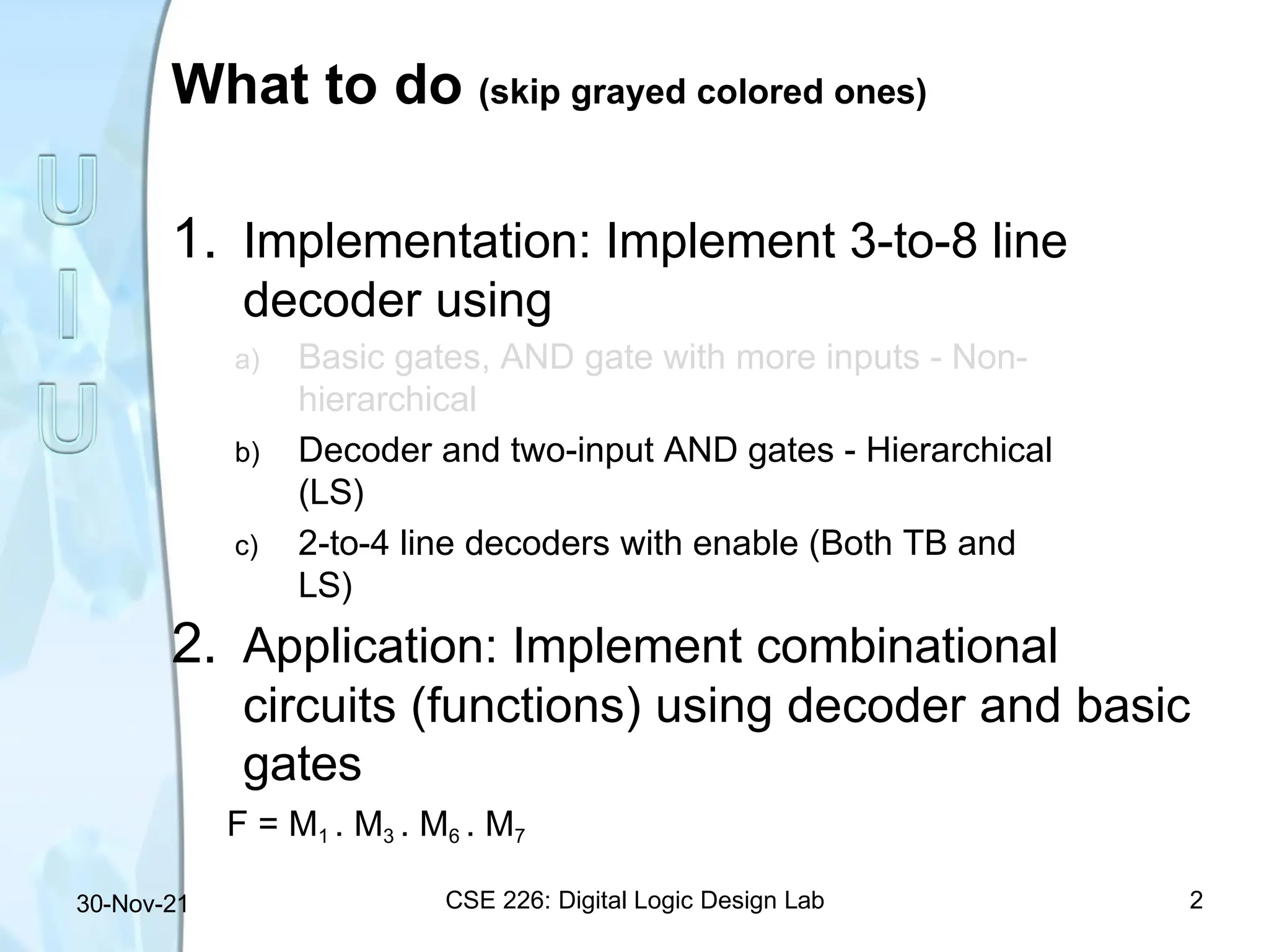
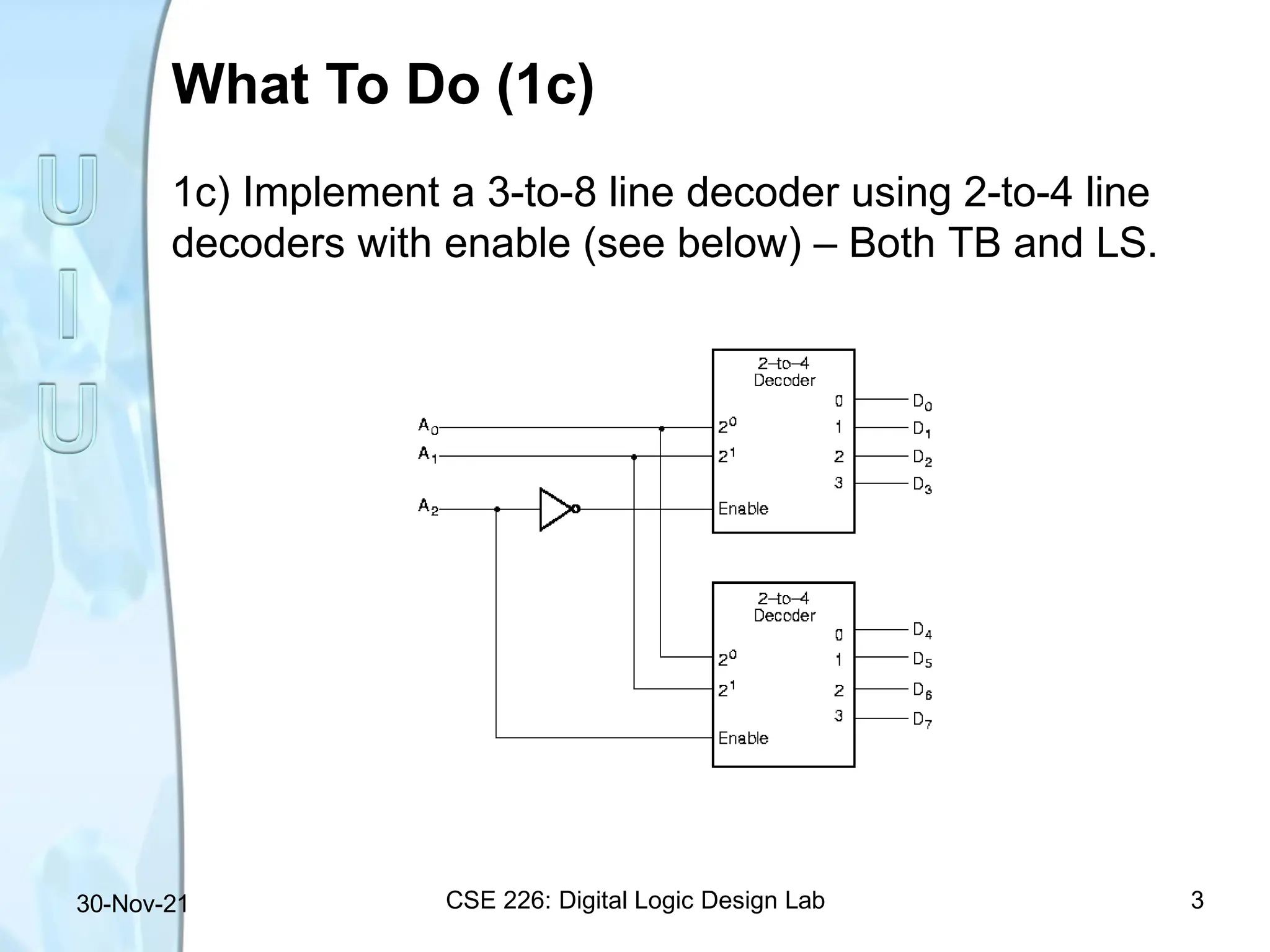
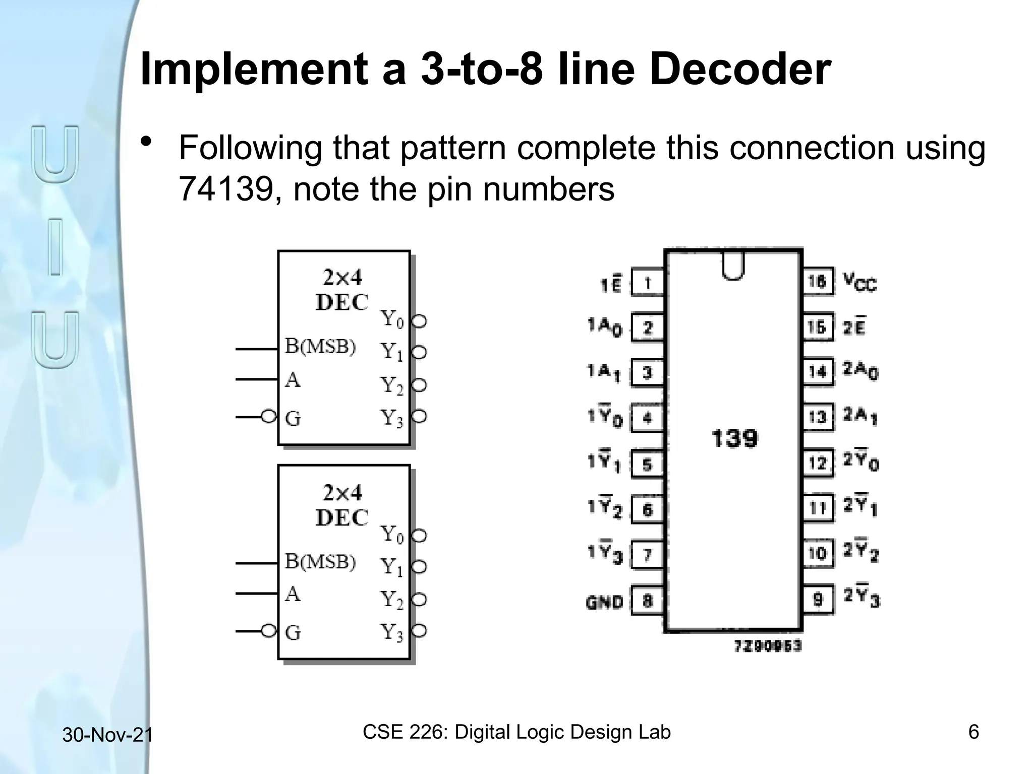
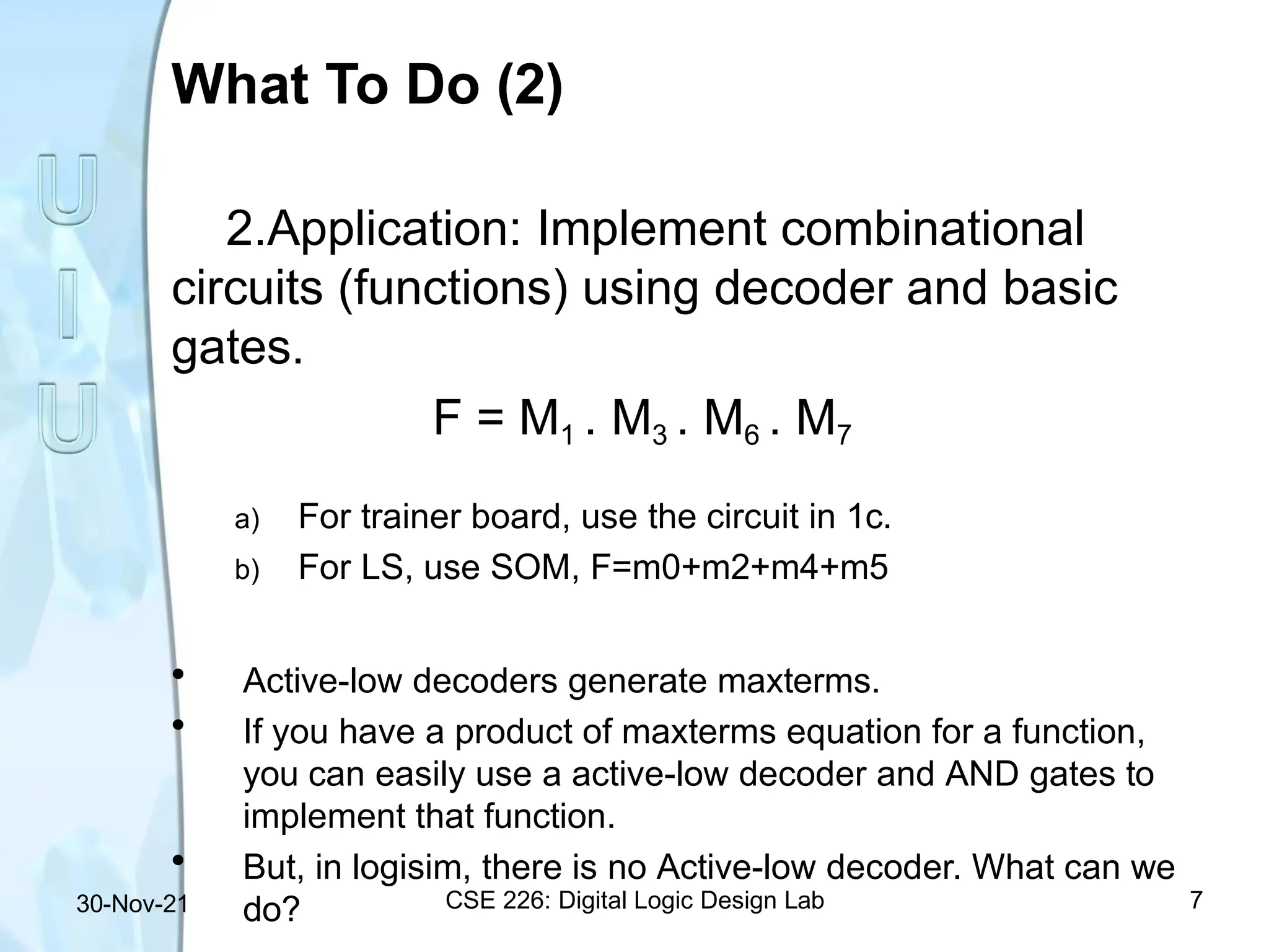
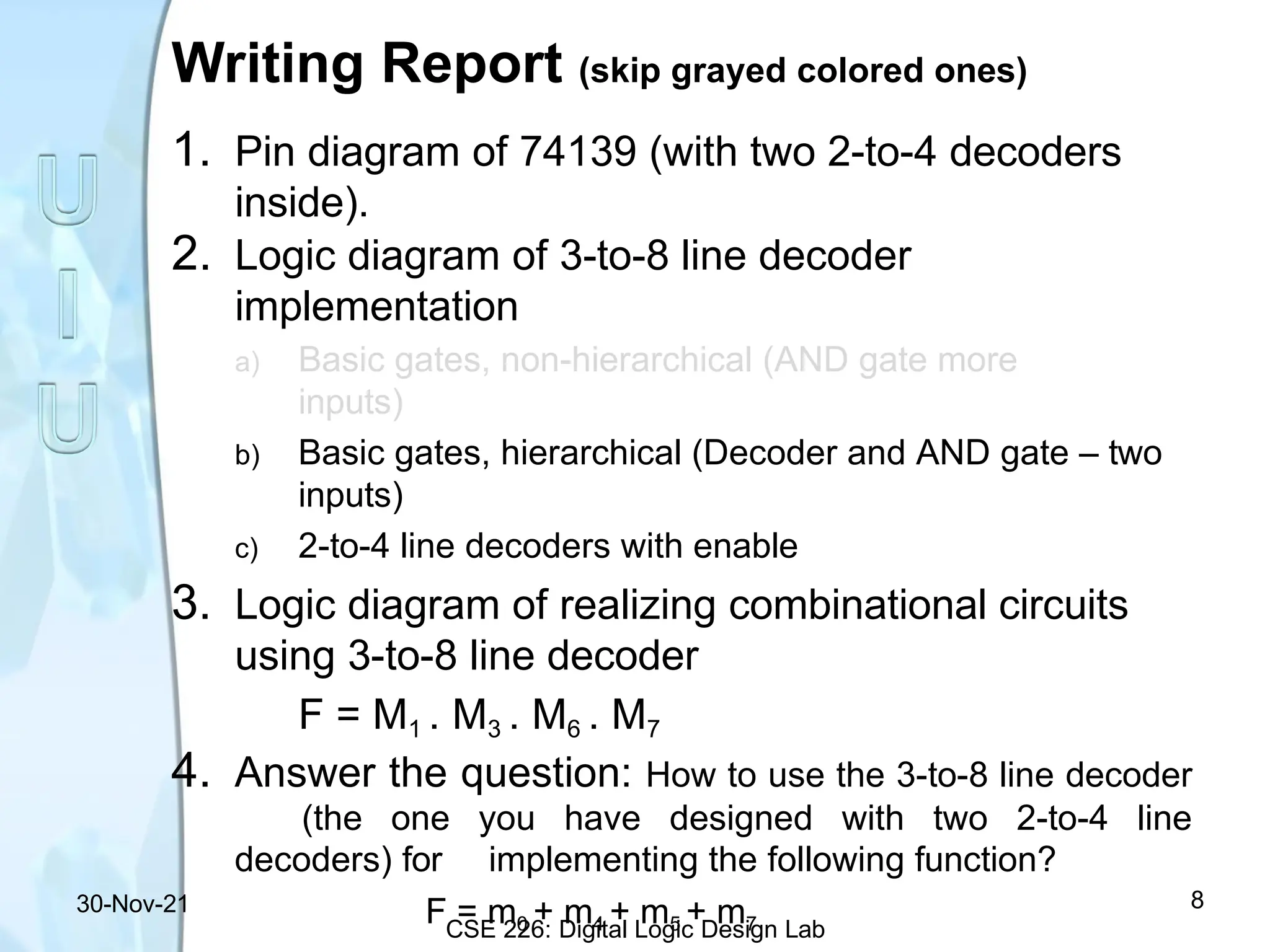
What to do (skip grayed colored ones)
CSE 226: Digital Logic Design Lab 2
30-Nov-21
1. Implementation: Implement 3-to-8 line
decoder using
a) Basic gates, AND gate with more inputs - Non-
hierarchical
b) Decoder and two-input AND gates - Hierarchical
(LS)
c) 2-to-4 line decoders with enable (Both TB and
LS)
2. Application: Implement combinational
circuits (functions) using decoder and basic
gates
F = M1 . M3 . M6 . M7
What To Do (1c)
1c) Implement a 3-to-8 line decoder using 2-to-4 line
decoders with enable (see below) – Both TB and LS.
CSE 226: Digital Logic Design Lab 3
30-Nov-21
IC: 74139 dual 2-to-4 Decoder
4
30-Nov-21
Functional/Pin Diagram
CSE 226: Digital Logic Design Lab 5
30-Nov-21
Implement a 3-to-8 line Decoder
• Following that pattern complete this connection using
74139, note the pin numbers
CSE 226: Digital Logic Design Lab 6
30-Nov-21
What To Do (2)
CSE 226: Digital Logic Design Lab 7
30-Nov-21
2.Application: Implement combinational
circuits (functions) using decoder and basic
gates.
F = M1 . M3 . M6 . M7
a) For trainer board, use the circuit in 1c.
b) For LS, use SOM, F=m0+m2+m4+m5
• Active-low decoders generate maxterms.
• If you have a product of maxterms equation for a function,
you can easily use a active-low decoder and AND gates to
implement that function.
• But, in logisim, there is no Active-low decoder. What can we
do?
Writing Report (skip grayed colored ones)
1. Pin diagram of 74139 (with two 2-to-4 decoders
inside).
2. Logic diagram of 3-to-8 line decoder
implementation
a) Basic gates, non-hierarchical (AND gate more
inputs)
b) Basic gates, hierarchical (Decoder and AND gate – two
inputs)
c) 2-to-4 line decoders with enable
3. Logic diagram of realizing combinational circuits
using 3-to-8 line decoder
F = M1 . M3 . M6 . M7
4. Answer the question: How to use the 3-to-8 line decoder
(the one you have designed with two 2-to-4 line
decoders) for implementing the following function?
F = m0 + m4 + m5 + m7
30-Nov-21
CSE 226: Digital Logic Design Lab
8

How Decoder works in Logic circuits.pptx

  • 2.
    What to do(skip grayed colored ones) CSE 226: Digital Logic Design Lab 2 30-Nov-21 1. Implementation: Implement 3-to-8 line decoder using a) Basic gates, AND gate with more inputs - Non- hierarchical b) Decoder and two-input AND gates - Hierarchical (LS) c) 2-to-4 line decoders with enable (Both TB and LS) 2. Application: Implement combinational circuits (functions) using decoder and basic gates F = M1 . M3 . M6 . M7
  • 3.
    What To Do(1c) 1c) Implement a 3-to-8 line decoder using 2-to-4 line decoders with enable (see below) – Both TB and LS. CSE 226: Digital Logic Design Lab 3 30-Nov-21
  • 4.
    IC: 74139 dual2-to-4 Decoder 4 30-Nov-21
  • 5.
    Functional/Pin Diagram CSE 226:Digital Logic Design Lab 5 30-Nov-21
  • 6.
    Implement a 3-to-8line Decoder • Following that pattern complete this connection using 74139, note the pin numbers CSE 226: Digital Logic Design Lab 6 30-Nov-21
  • 7.
    What To Do(2) CSE 226: Digital Logic Design Lab 7 30-Nov-21 2.Application: Implement combinational circuits (functions) using decoder and basic gates. F = M1 . M3 . M6 . M7 a) For trainer board, use the circuit in 1c. b) For LS, use SOM, F=m0+m2+m4+m5 • Active-low decoders generate maxterms. • If you have a product of maxterms equation for a function, you can easily use a active-low decoder and AND gates to implement that function. • But, in logisim, there is no Active-low decoder. What can we do?
  • 8.
    Writing Report (skipgrayed colored ones) 1. Pin diagram of 74139 (with two 2-to-4 decoders inside). 2. Logic diagram of 3-to-8 line decoder implementation a) Basic gates, non-hierarchical (AND gate more inputs) b) Basic gates, hierarchical (Decoder and AND gate – two inputs) c) 2-to-4 line decoders with enable 3. Logic diagram of realizing combinational circuits using 3-to-8 line decoder F = M1 . M3 . M6 . M7 4. Answer the question: How to use the 3-to-8 line decoder (the one you have designed with two 2-to-4 line decoders) for implementing the following function? F = m0 + m4 + m5 + m7 30-Nov-21 CSE 226: Digital Logic Design Lab 8