Differential vs Single-EndedRouting
• Differential routing provides improved EMI and crosstalk performance
over single-ended traces. This is especially useful for dense layouts
with many signal lines.
• Recommendations
– Either single-ended or differential can be used, but you should stick with one
or the other for the full length.
• For instance, if the signal coming out of the transmitter is differential then route the
signal differential all the way to the receiver.
• Do not come out of the transmitter differential then split into single-ended traces
and then come back to differential at the receiver. Each split will create a
discontinuity in the trace impedance.
– For most designs, there is no reason to deviate away from differential
routing for the high-speed serial link signals.
2
3.
Routing of DifferentialTraces
• Recommendations:
– Keep the distance between the differential traces (S) constant over the
entire trace length
– Keep the length of the individual traces of the differential pair the same to
minimize skew and phase differences.
– For tightly coupled differential traces (S = W), keep the distance (D)
between adjacent signals and other objects or routing greater than 3 to 5
times the width (W) of the trace (D > 3 * W).
– For loosely coupled differential traces (S > 2 * W) or single-ended traces
keep adjacent signals away at a distance of 3 to 5 times the height of the
dialectric (D > 3 * H).
– Tightly coupled traces have better crosstalk performance but more loss.
3
4.
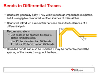
Bends in DifferentialTraces
• Bends are generally okay. They will introduce an impedance mismatch,
but it is negligible compared to other sources of mismatches.
• Bends will introduce a mismatch between the individual traces of a
differential pair.
• Recommendations:
– Use bends in the opposite direction to
correct for mismatches.
– Use 45° bends rather than 90° bends.
To make a 90° bend, use two 45° bends.
• Rounded bends can also be used but it may be harder to control the
spacing of the traces throughout the bend.
4
5.
Mismatches Between theIndividual
Traces of a Differential Pair
• Mismatches between the individual traces will cause a skew between
the positive and negative signals of the differential pair. This will
decrease the opening of the data eye.
• Recommendations:
– If the mismatch is created by a bend, then a bend in the opposite direction
will fix the mismatch. Otherwise, use jog-outs to increase the length of one
side.
– Use multiple small jog-outs instead of one large jog-out. Jog-outs will cause
an impedance mismatch.
5
Equal number of bends
in each direction
Multiple small jog-outs
to fix mismatch
6.
Wiggles to MatchTrace Lengths
• Wiggles are used to match the lengths of multiple differential pairs.
• Recommendations:
– Wiggles should follow the recommendations for bends given previously.
– Rule of thumb: keep the diameter of the wiggle at least 3 times trace width.
– Use an equal number of turns in each direction to keep the traces of the
differential pair matched.
• Lanes of matched length are not necessary
for the JESD204b standard. Large mismatch
between lanes can result in higher latency.
6
D > 3xW
Wiggles used to match the
length of two differential pairs
7.
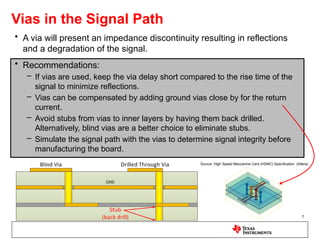
Vias in theSignal Path
• A via will present an impedance discontinuity resulting in reflections
and a degradation of the signal.
• Recommendations:
– If vias are used, keep the via delay short compared to the rise time of the
signal to minimize reflections.
– Vias can be compensated by adding ground vias close by for the return
current.
– Avoid stubs from vias to inner layers by having them back drilled.
Alternatively, blind vias are a better choice to eliminate stubs.
– Simulate the signal path with the vias to determine signal integrity before
manufacturing the board.
7
Source: High Speed Mezzanine Card (HSMC) Specification (Altera)
8.
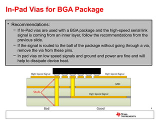
In-Pad Vias forBGA Package
• Recommendations:
– If In-Pad vias are used with a BGA package and the high-speed serial link
signal is coming from an inner layer, follow the recommendations from the
previous slide.
– If the signal is routed to the ball of the package without going through a via,
remove the via from these pins.
– In pad vias on low speed signals and ground and power are fine and will
help to dissipate device heat.
8
9.
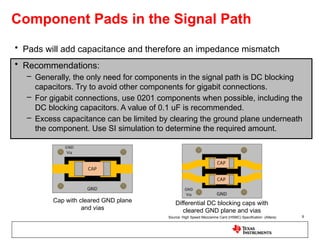
Component Pads inthe Signal Path
• Pads will add capacitance and therefore an impedance mismatch
• Recommendations:
– Generally, the only need for components in the signal path is DC blocking
capacitors. Try to avoid other components for gigabit connections.
– For gigabit connections, use 0201 components when possible, including the
DC blocking capacitors. A value of 0.1 uF is recommended.
– Excess capacitance can be limited by clearing the ground plane underneath
the component. Use SI simulation to determine the required amount.
9
Cap with cleared GND plane
and vias
Differential DC blocking caps with
cleared GND plane and vias
Source: High Speed Mezzanine Card (HSMC) Specification (Altera)
10.
Reference Planes
• Recommendations:
–Use a single ground plane as the signal reference.
– Do not put splits in the reference plane underneath the signals. The return
current for high-speed signals will follow the trace on the reference plane. A
split will require the return current to travel around the split.
– Keep analog signals separate from digital signals, however a single ground
plane is fine. During routing, split the ground plane at the DAC or ADC into
analog and digital planes and route the signal traces in their respective
domains. After routing, recombine the two ground planes into one.
– If using a stripline trace, place reference planes on both the top and bottom
of the trace and do not put splits into either of them.
10
11.
Summary of Recommendations
•Always take steps to minimize impedance discontinuities, meaning that
the traces should be uniform from source to load.
• Use differential routing for most designs and stick to it for the full trace
length.
• Keep the differential trace spacing constant and the individual traces
within the pair equal length.
• Keep adjacent traces and objects a sufficient distance away to avoid
crosstalk.
• Only use bends of 45°. Use two 45° bends for 90° turns.
• Use multiple small jog-outs to correct mismatch between traces of a
differential pair.
• Avoid stubs from vias by backdrilling or using blind vias. Add ground
vias close by to account for return currents.
• Do not split the reference planes underneath the signals.


![Signal Integrity - A Crash Course [R Lott]](https://cdn.slidesharecdn.com/ss_thumbnails/1cb0870c-cad3-4a68-ad41-8e9450fec5d8-170217191645-thumbnail.jpg?width=640&height=640&fit=bounds)