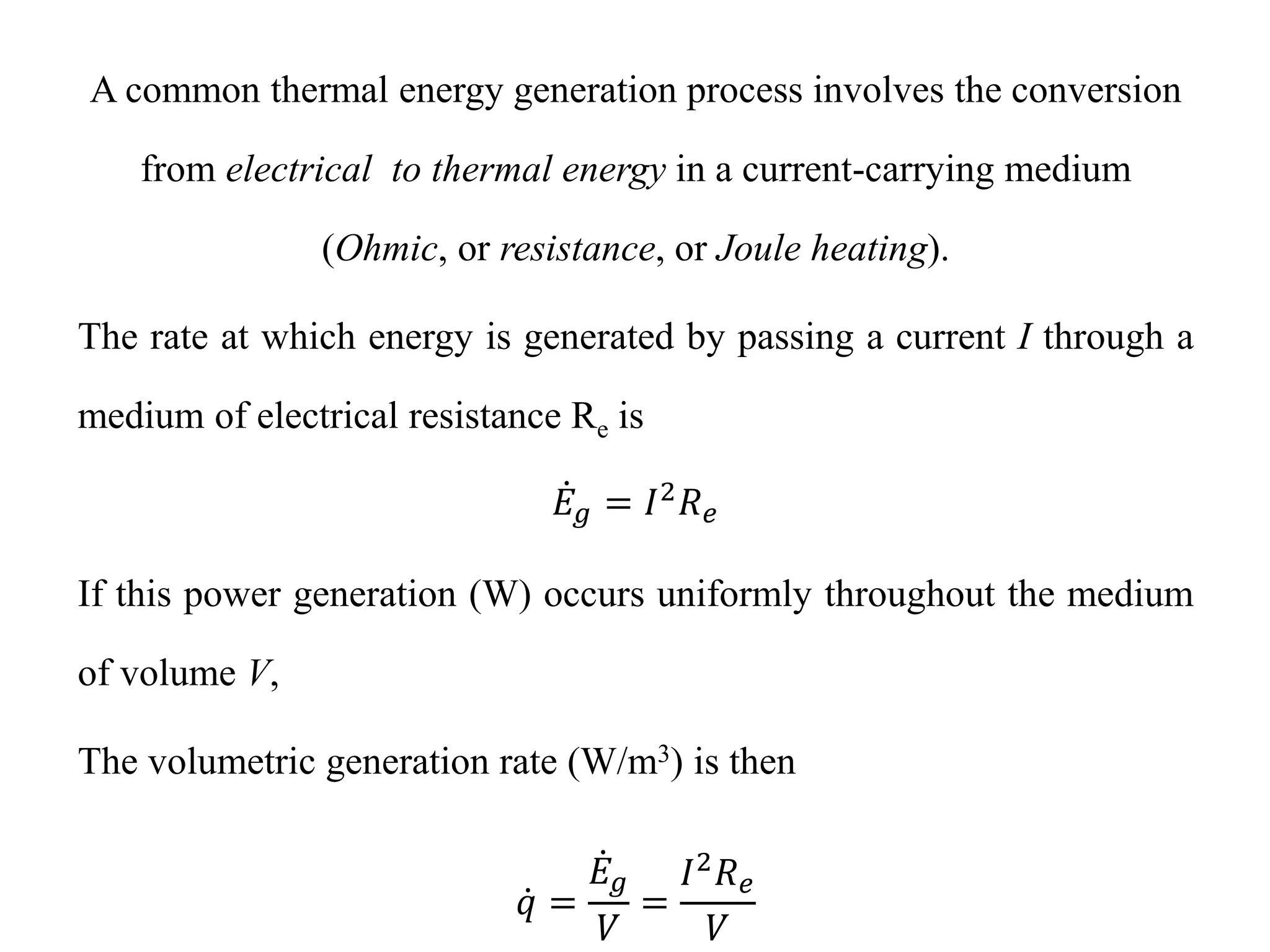
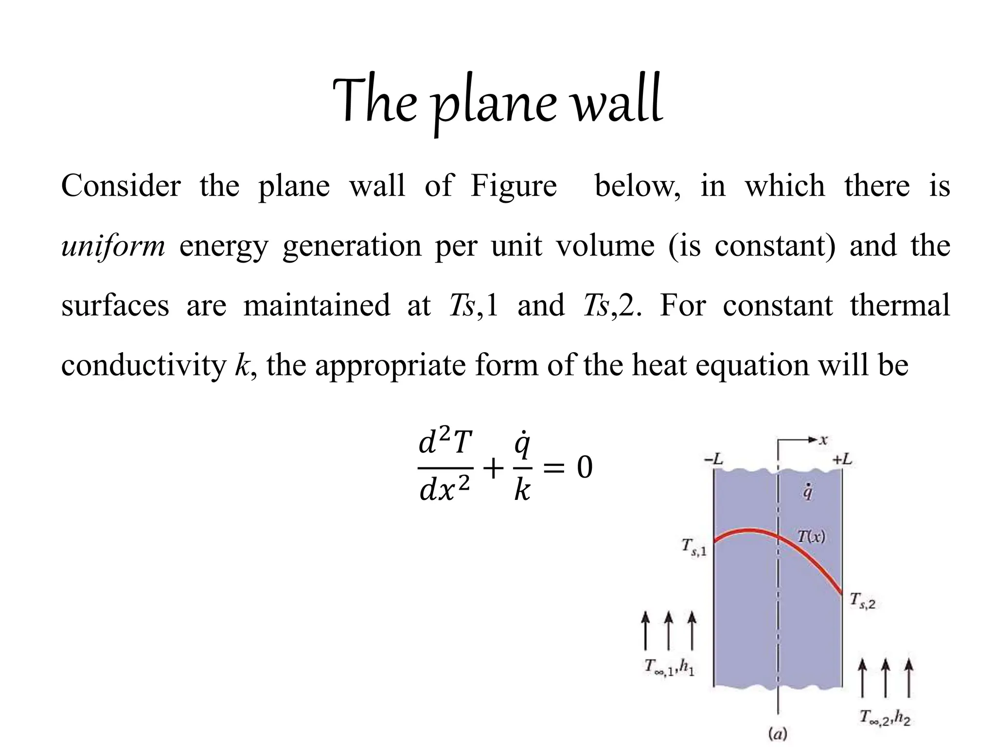
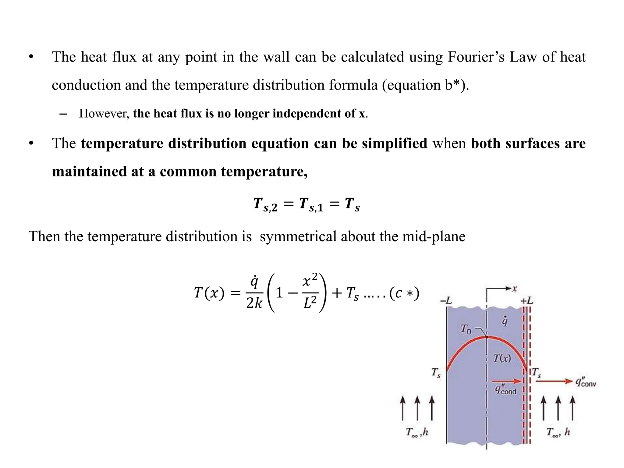
Heat Conduction analysis is done in one dimensional steady state heat conduction considering internal heat generation per unit volume on plane and radial walls. Examples are directly taken from textbooks.
2. A common thermal energy generation process involves the conversion
from electrical to thermal energy in a current-carrying medium
(Ohmic, or resistance, or Joule heating).
The rate at which energy is generated by passing a current I through a
medium of electrical resistance Re is
𝐸𝑔 = 𝐼2
𝑅𝑒
If this power generation (W) occurs uniformly throughout the medium
of volume V,
The volumetric generation rate (W/m3) is then
𝑞 =
𝐸𝑔
𝑉
=
𝐼2𝑅𝑒
𝑉
3. Energy generation may also occur as a result of
• The deceleration and the absorption of neutrons in the fuel
element of nuclear reactor
• Exothermic chemical reactions occurring within a medium.
While Endothermic reaction has the reverse effect.
• Conversion of electromagnetic to thermal energy due to
absorption of radiation within a medium
4. The plane wall
Consider the plane wall of Figure below, in which there is
uniform energy generation per unit volume (is constant) and the
surfaces are maintained at Ts,1 and Ts,2. For constant thermal
conductivity k, the appropriate form of the heat equation will be
𝑑2
𝑇
𝑑𝑥2
+
𝑞
𝑘
= 0
5. The general solution is
𝑇(𝑥) =
𝑞
2𝑘
𝑥2
+ 𝐶1𝑥 + 𝐶2 … . . (𝑎 ∗)
Where 𝐶1& 𝐶2 are constants of integration.
The boundary conditions to solve 𝐶1& 𝐶2 will be
𝑇 −𝐿 = 𝑇𝑠,1 𝑎𝑛𝑑 𝑇 𝐿 = 𝑇𝑠,2
The constants are evaluated to be
𝐶1 =
𝑇𝑠,2 − 𝑇𝑠,1
2𝐿
𝑎𝑛𝑑 𝐶2 =
𝑞
2𝑘
𝐿2
+
𝑇𝑠,1 − 𝑇𝑠,2
2
Then the temperature distribution is
𝑻(𝒙) =
𝒒
𝟐𝒌
𝟏 −
𝒙𝟐
𝑳𝟐 +
𝑻𝒔,𝟐 − 𝑻𝒔,𝟏
𝟐
𝒙
𝑳
+
𝑻𝒔,𝟏 − 𝑻𝒔,𝟐
𝟐
… . . (𝑏 ∗)
6. • The heat flux at any point in the wall can be calculated using Fourier’s Law of heat
conduction and the temperature distribution formula (equation b*).
– However, the heat flux is no longer independent of x.
• The temperature distribution equation can be simplified when both surfaces are
maintained at a common temperature,
𝑻𝒔,𝟐 = 𝑻𝒔,𝟏 = 𝑻𝒔
Then the temperature distribution is symmetrical about the mid-plane
𝑇(𝑥) =
𝑞
2𝑘
1 −
𝑥2
𝐿2
+ 𝑇𝑠 … . . (𝑐 ∗)
7. • The maximum temperature exists at the mid-plane
𝑇 0 = 𝑇0 =
𝑞𝐿2
2𝑘
+ 𝑇𝑠
• in which case the temperature distribution, may be expressed as
dimensionless
𝑇 𝑥 − 𝑇0
𝑇𝑠 − 𝑇0
=
𝑥
𝐿
2
• It is important that at the plane of symmetry, the temperature
gradient is zero(
𝑑𝑇
𝑑𝑥
=0). Accordingly there is no heat transfer
across the plane, and it may be represented by adiabatic
surface.
• The temperature distribution equation (c*) is also applicable to a
plane walls that are perfectly insulated on one side (x=0) and
maintained at a fixed temperature (Ts) on the other side(x=L).
8. • To use the foregoing results, the surface temperature(s) Ts must be known.
– A common situation is one for which it is the temperature of an adjoining fluid, T, and not Ts, which
is known. It then becomes necessary to relate Ts to T.
– This relation may be developed by applying a surface energy balance.
• Consider the surface at x = L for the symmetrical plane wall or the insulated plane wall. Neglecting radiation and
substituting the appropriate rate equations, the energy balance given by the equation reduces to
−𝑘
𝑑𝑇
𝑑𝑥 𝑥=𝐿
= ℎ 𝑇𝑠 − 𝑇∞
Substituting equation (***) to obtain the temperature gradient at x=L,
𝑇𝑠 = 𝑇∞ +
𝑞𝐿
ℎ
… . . (𝑑 ∗)
Hence 𝑇𝑠 may be computed from the knowledge of 𝑇∞, 𝑞, 𝐿 𝑎𝑛𝑑 ℎ.
9. • Equation (d*) may also be obtained by applying an overall energy balance to the plane wall of
symmetric temperature or adiabatic wall.
• For example, relative to a control surface about the wall of adiabatic wall, the rate at which
energy is generated within the wall must be balanced by the rate at which energy leaves via
convection at the boundary. Then the energy balance reduces to
𝐸𝑔 = 𝐸𝑜𝑢𝑡
For a unit surface
𝑞𝐿 = ℎ 𝑇𝑠 − 𝑇∞
Solving for Ts, Equation (d*) is obtained
10. Radial System
• Heat generation may occur in a variety of radial geometries
• Consider the long, solid cylinder of below, which could represent a current-carrying wire or a
fuel element in a nuclear reactor.
• For steady-state conditions, the rate at which heat is generated within the cylinder must
equal the rate at which heat is convected from the surface of the cylinder to a moving
fluid. This condition allows the surface temperature to be maintained at a fixed value of Ts.
• To determine the temperature distribution in the cylinder, we begin with the appropriate form
of the heat equation. For constant thermal conductivity k, heat diffusion equation becomes
1
𝑟
𝑑
𝑑𝑟
𝑟
𝑑𝑇
𝑑𝑟
+
𝑞
𝑘
= 0
Separating variables
𝑟
𝑑𝑇
𝑑𝑟
= −
𝑞
𝑘
+ 𝐶1 … . (5 ∗)
Repeating the procedure, the general solution for the temperature
distribution becomes
𝑇 𝑟 = −
𝑞
𝑘
𝑟2
+ 𝐶1 ln 𝑟 + 𝐶2 … . (6 ∗)
11. • To obtain the constants of integration C1 and C2, we apply the boundary conditions
𝑑𝑇
𝑑𝑟 𝑟=0
= 0 𝑎𝑛𝑑 𝑇 𝑟0 = 𝑇𝑠
• The first condition results from the symmetry of the situation. That is, for the solid cylinder
the centreline is a line of symmetry for the temperature distribution and the temperature
gradient must be zero.
• From the symmetry condition at r=0 and Equation (𝟓 ∗), it is evident that C1=0. Using the
surface boundary condition at r=ro with Equation (6*), then we obtain
𝐶2 = 𝑇𝑠 +
𝑞
4𝑘
𝑟0
2
Then the temperature distribution is therefore
𝑇 𝑟 =
𝑞
4𝑘
𝑟0
2
1 −
𝑟2
𝑟0
2 + 𝑇𝑠 … . (7 ∗)
12. • Evaluating Equation 3.58 at the centreline and dividing the result into Equation 3.58, we obtain
the temperature distribution in non-dimensional form
𝑇 𝑟 − 𝑇𝑠
𝑇0 − 𝑇𝑠
= 1 −
𝑟
𝑟0
2
… . (8 ∗)
where To is the centreline temperature. The heat rate at any radius in the cylinder may, of course,
be evaluated by using Equation (7*) with Fourier’s law.
• To relate the surface temperature, Ts, to the temperature of the cold fluid T, either a surface
energy balance or an overall energy balance may be used. Choosing the second
approach, we obtain
𝑞 2𝜋𝑟0
2
𝐿 = ℎ 2𝜋𝑟0𝐿 𝑇𝑠 − 𝑇∞
OR
𝑇𝑠 = 𝑇∞ +
𝑞𝑟0
2ℎ
13.
14.
15. From the prescribed physical conditions, the temperature in the composite is
known to have
(a) Parabolic in material A, due to the presence of uniform volumetric heat generation
(b) Zero gradient at insulated boundary
(c) Linear in material B, which is a plane wall with no uniform volumetric heat
generation
(d) Slope change at the interface
The temperature distribution in
the water is characterized by
(e) Large gradient near the surface
16. See Example 3.8 on page 151 of the book
Theodore L. Bergman, Adrienne S. Lavine,
David P. DeWitt, Frank P. Incropera-
Introduction to Heat Transfer, Sixth Edition -
John Wiley & Sons, Inc. (2011)
17. The rate of heat transfer from a surface at a temperature Ts to the
surrounding medium at T is given by Newton’s law of cooling as
𝑸𝑪𝒐𝒏𝒗 = 𝒒𝒄𝒐𝒏𝒗 = 𝒉𝑨𝒔 𝑻𝒔 − 𝑻∞
where As is the heat transfer surface area &
h is the convection heat transfer coefficient.
Heat Transfer from Extended Surface
18. When the temperatures Ts and T are fixed by design considerations, as is often the case,
there are two ways to increase the rate of heat transfer:
1. To increase the convection heat transfer coefficient, h :- Increasing h may require
the installation of a pump or fan, or
replacing the existing one with a larger one,
But this approach may or may not be practical. Besides, it may not be adequate
OR
2. To increase the surface area, As :- Increasing the surface area by attaching to the surface
extended surfaces called fins made of highly conductive materials such as aluminium.
Finned surfaces are manufactured by extruding, welding, or wrapping a thin metal sheet
on a surface.
Fins enhance heat transfer from a surface by exposing a larger surface area to
convection and radiation.
19. Finned surfaces are commonly used in practice to enhance heat transfer, and
they often increase the rate of heat transfer from a surface several fold.
The car radiator shown in figure below is an example of a finned surface.
The closely packed thin metal sheets attached to the hot water tubes increase the surface
area for convection and thus the rate of convection heat transfer from the tubes to the
air many times.
20. In the analysis of fins, we consider
steady operation
no heat generation in the fin,
the thermal conductivity k of the material to remain
constant
It is also assumed that
the convection heat transfer coefficient, h to be constant
and uniform over the entire surface of the fin for
convenience in the analysis
22. The convection heat transfer rate may be expressed as
where dAs is the surface area of the differential element.
Substituting the foregoing rate equations into the energy
balance, we obtain
or
23. general form of the energy equation for an
extended surface.
Its solution for appropriate boundary conditions
provides the temperature distribution, which may
be used with Fourier’s Law to calculate the
conduction rate at any x.
24. Fin Configuration
a) Straight fin of Uniform Cross Section
b) Straight fin of non-Uniform Cross Section
c) Annular Fin
d) Pin fin