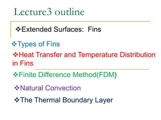
1. Lecture3 outline
Extended Surfaces: Fins
Types of Fins
Heat Transfer and Temperature Distribution
in Fins
Finite Difference Method(FDM)
Natural Convection
The Thermal Boundary Layer
2. Extended Surfaces: Fins
We begin with Newton's law of cooling for surface heat
transfer by convection
This equation provides an insight as to the options available for
increasing surface heat transfer rate qs.
One option is to increase the heat transfer coefficient h by
changing the fluid and/or manipulating its motion;
A second option is to lower the ambient temperature T;
A third option is to increase surface area As.
3. This third option is exercised in many engineering
applications in which the heat transfer surface is "extended" by
adding fins.
Inspect the back side of your refrigerator where the
condenser is usually placed and note the many thin rods
attached to the condenser’s tube. The rods are added to
increase the rate of heat transfer from the tube to the
surrounding air and thus avoid using a fan.
Other examples include the honeycomb surface of a car
radiator, the corrugated surface of a motorcycle engine, and the
disks attached to a baseboard radiator.
The purpose of extended surfaces (commonly known as fins)
is to enhance convective heat transfer from surfaces.
They are commonly used in situations in which cooling is
attained via free (or natural) convection – for which the heat
transfer coefficients h are relatively small.
4. Typically fins are much longer than they are thick;
Because of this it is common, and fairly accurate, to assume
that the temperature varies only in the lengthwise direction. That
is, at any point x along the length of the fin the temperature is
essentially uniform across the cross section of the fin.
What results from this assumption is a one–dimensional heat
transfer problem – yet the 1–D DE cannot be directly applied to
analyze the fin. Rather, an energy conservation equation specific
to the fin must be derived.
Consider an arbitrary fin. The heat flow direction is x, and the
cross sectional area of the fin (the area exposed to the heat flow)
is taken to be a function of x. Consider the small volume element
of the fin of length ∆x. An energy balance is performed on this
element, in which it is assumed that the element is at a constant
and uniform temperature of T.
Substitution of the rate laws of conduction and convection gives:
5. The fin equation is:
The typical boundary condition at the base (x = 0) is T
= TB , i.e., the base temperature is specified. Three forms
of boundary condition can be specified at the fin tip, i.e.,
specified temperature, specified flux, or convection. Before
introducing further details, the dependent and independent
variables are made dimensionless by the definitions
6. for which, the fin equation becomes:
The three boundary conditions at the tip are:
7. If heat is transferred from a surface, then a temperature
gradient must exist normal to the surface to supply the heat.
More specifically, if y denotes the direction normal to the
surface area, then the energy balance at the surface would give
8. Types of Fins
Various geometries and configurations are used to construct fins.
(Examples are shown in fig.2.5 below).
Each fin is shown attached to a wall or surface;
The end of the fin which is in contact with the surface is called
the base while the free end is called the tip;
The term straight is used to indicate that the base extends
along the wall in a straight fashion as shown in (a) and (b).
If the cross-sectional area of the fin changes as one move from
the base towards the tip, the fin is characterized as having a
variable cross-sectional area. Examples are the fins shown in (b),
(c) and (d).
A spine or a pin fin is distinguished by a circular cross section as
in (c). A variation of the pin fin is a bar with a square or other
cross-sectional geometry.
An annular or cylindrical fin is a disk which is mounted on a tube
as shown in (d). Such a disk can be either of uniform or variable
thickness.
9.
10. Heat Transfer and Temperature Distribution in
Fins
In the pin fin shown in Fig. 2.6, heat is removed from the wall at the
base and is carried through h of the fin by conduction in both the axial
and radial directions;
At the fin surface, heat in x exchanged with the surrounding fluid by
convection. Thus the h direction of heat flow is two- dimensional.
Examining the temperature profile at any axial location x we note that
temperature variation in the lateral or radial direction is barely noticeable
near the center of the fin. However, it becomes more pronounced near its
surface.
This profile changes as one proceeds towards the tip. Thus
temperature distribution is also two-dimensional.
11. An important simplification made in the analysis of fins is based on the assumption that
temperature variation in the lateral direction is negligible. The question is, under what
conditions can this approximation be made? Let us try to develop a criterion for justifying
this assumption.
First, the higher the thermal conductivity is the more uniform the temperature will be
at a given cross section.;
Second, a low heat transfer coefficient tends to act as an insulation layer and thus
forcing a more uniform temperature in the interior of the cross section.;
Third, the smaller the half thickness is the smaller the temperature drop will be
through the cross section. Assembling these three factors together gives a
dimensionless ratio, hδ/k, which is called the Biot number. Therefore, based on the
above reasoning, the criterion for assuming uniform temperature at a given cross section
is a Biot number which is small compared to unity. That is
12. Comparisons between exact and approximate solutions
have shown that this simplification is justified when the Biot
number is less than 0.1;
Note that δ/k represents the internal conduction
resistance and 1/h is the external convection resistance.
Rewriting the Biot number as Bi = (δ/k) /(1/ h) shows
that it represents the ratio of the internal and external
resistances.
13. Analytical solutions that allow for the determination of the exact
temperature distribution are only available for limited ideal cases;
Graphical solutions have been used to gain an insight into
complex heat transfer problems, where analytical solutions are not
available, but they have limited accuracy and are primarily used
for two-dimensional problems;
Advances in numerical computing now allow for complex heat
transfer problems to be solved rapidly on computers, i.e.
"numerical techniques“.
Current numerical techniques include: finite-difference method;
finite element analysis (FEA); and finite-volume analysis.
In general, these techniques are routinely used to solve
problems in heat transfer, fluid dynamics, stress analysis,
electrostatics and magnetics, etc.
We will show the use of finite-difference analysis to solve
conduction heat transfer problems.
FINITE DEFFERENCE METHOD (FDM)
14. Finite-difference Analysis
Numerical techniques result in an approximate solution, however the error
can be made very small.
properties (e.g., temperature) are determined at discrete points in the region
of interest-these are referred to as nodal points or nodes. Consider the finite-
difference technique for 2-D conduction heat transfer:
in this case each node represents the temperature of a point on the surface
being considered.
the temperature at the node represents the average temperature of that
region of the surface.
algebraic expressions are used to define the relationship between adjacent
nodes on the surface –usually the boundary conditions are specified.
by increasing the number of nodes on the surface being considered it is
possible to increase the spatial resolution of the solution and to potentially
increase the accuracy of the numerical solution, however this increases the
number of calculation is required to obtain a solution to the problem.
15. Discrete Grid Points
∆x and ∆y – spacing in positive x and y direction
∆x and ∆y not necessarily uniform
In some cases, numerical calculations performed on transformed computational
plane having uniform spacing in transformed variables but non uniform spacing in
physical plane
Grid points identified by indices i and j in positive x and y direction respectively
16.
17.
18.
19.
20.
21.
22.
23.
24.
25.
26.
27. Classification of Partial Differential Equations
Linear Equations: A,B,C,D,E and F are constants or f(x,y)
Non-linear Equations: A,B,C,D,E and F contain φor its derivatives
Quasilinear Equations: Important subclass of nonlinear equations.
A,B,C,D,E and F may be function of φor its first derivatives
Homogeneous: G=0
Parabolic Equation: B2- 4AC = 0
Elliptic Equation: B2 – 4AC < 0
Hyperbolic Equation: B2 – 4AC > 0
28. Navier Stokes Equation is elliptic in space and parabolic in
time
Laplace equation and Poisson Equation are elliptic
Fluid flow problems have non-linear terms called advection
and convection terms in momentum and energy equations
respectively
FDM basic philosophy:
Replace derivatives of governing equations with algebraic difference
quotients
Results in a system of algebraic equations solvable for dependent variables
at discrete grid points
Analytical solutions provide closed-form expressions – variation of
dependent variables in the domain
Numerical solutions (finite difference) - values at discrete points in the
domain
29. Elementary Finite Difference Quotients
Taylor Series Expansion:
For small ∆x higher order terms can be neglected.
30.
31.
32.
33.
34. Natural Convection
In natural convection, the fluid motion occurs by natural means su
ch as buoyancy. Since the fluid velocity associated with natural c
onvection is relatively low, the heat transfer coefficient encounter
ed in natural convection is also low.
Mechanisms of Natural Convection
Consider a hot object exposed to cold air. The temperature of the
outside of the object will drop (as a result of heat transfer with col
d air), and the temperature of adjacent air to the object will rise. C
onsequently, the object is surrounded with a thin layer of warmer a
ir and heat will be transferred from this layer to the outer layers of
air.
35. The temperature of the air adjacent to the hot object is higher, thu
s its density is lower. As a result, the heated air rises. This movem
ent is called the natural convection current. Note that in the absen
ce of this movement, heat transfer would be by conduction only an
d its rate would be much lower. In a gravitational field, there is a
net force that pushes a light fluid placed in a heavier fluid upward
s. This force is called the buoyancy force .
36. Natural Convection over Surfaces
Natural convection on a surface depends on the geom
etry of the surface as well as its orientation. It also depe
nds on the variation of temperature on the surface and t
he thermophysical properties of the fluid.
The velocity and temperature distribution for natural co
nvection over a hot vertical plate are shown in figure
below.
Note that the velocity at the edge of the boundary laye
r becomes zero. It is expected since the fluid beyond th
e boundary layer is stationary.
37.
38. The shape of the velocity and temperature profiles, in the cold plate case, remains the
same but their direction is reversed.
Natural Convection Correlations
The complexities of the fluid flow make it very difficult to obtain simple analytical
relations for natural convection. Thus, most of the relationships in natural convection a
re based on experimental correlations.
The Rayleigh number is defined as the product of the Grashof and Prandtl numbers:
The Nusselt number in natural convection is in the following form:
where the constants C and n depend on the geometry of the surface and the flow
39.
40. Natural Convection from Finned Surfaces
Finned surfaces of various shapes (heat sinks) are used in microelectronics cooling.
One of most crucial parameters in designing heat sinks is the fin spacing, S. Closely
packed fins will have greater surface area for heat transfer, but a smaller heat transfe
r coefficient (due to extra resistance of additional fins). A heat sink with widely space
d fins will have a higher heat transfer coefficient but smaller surface area. Thus, an o
ptimum spacing exists that maximizes the natural convection from the heat sink.
41.
42. The fluid flow results from either an imposed pressure drop or an induced
buoyancy respectively called-forced and free convection.
Nu and Bi
Conduction
w
f
Convection
ww
y
T
kTThq
)(
))(/(
)(
)(
/
TTly
TT
l
k
TT
yT
kh
w
wf
W
w
f
*
*
y
T
k
hl
Nu
f
43. l
y
y *
TT
TT
T
W
W*
Where, Nusselt Number is the dimensionless fluid
temperature gradient at the surface (or wall) But, the Biot
Number is
resistencethermallayerBoundary
solidaofceresisthermalInternal
k
hl
Bi
s
tan
)(
44. Transport Phenomena
Due to non-uniform distributed field
Transport of momentum velocity gradient→momentum transfer
viscous stress
Transport of Heat
Temperature gradient→heat transfer
Transport of mass
Concentration gradient→mass flux
45. Forced convection in Laminar Flow
The concept of Boundary Layer
Boundary Layer theory was proposed by Prandtl shortly after the completion
of his doctoral dissertation in 1904. The Velocity Boundary Layer or
The Thermal Boundary Layer
The Thermal Boundary Layer
46. uu 99.0
The quantity “δ”is termed the B.L thickness and it is typically defined as the
value of y for which
With increasing distance from the leading edge, the effects of viscosity
penetrate farther into the free stream and the B.L. grows (i.e.
).
The velocity B.L. is of extent and is characterized by the presence of velocity gradients
and shear stress
For external flows, it provides the basis for determining the local friction
coefficient
47. The Thermal B.L
δ(x), termed the B.L thickness is typically defined as the value of y for which
the ratio
99.0
TT
TT
W
W
With increasing distance from the leading edge, the effects of heat transfer penetrate
farther into the free stream and the thermal B.L. grows.
At any distance x from the loading edge, the local Heat flux may be obtained by
applying Fourier Law to the fluid at y=0. That is
48. The above (relation) expression is appropriate because at the surface,
there is no fluid motion and energy transfer occurs only by conduction.
Further, with Newton’s Law of cooling
and
In summary the thermal B.L. is of extent x and is characterized by temperature
gradients and heat transfer.
49. Questions
Q1.A large vertical plate 4 m high is maintained at 60°C and exposed to atmosp
heric air at 10°C. Calculate: (a) Raylegh number; (b) Nusselt number; (c) heat
transfer coefficient and (d) the heat transfer if the plate is 10 m wide. The
properties are: 𝛃 = 1/308, k = 0.0285 W/mK, 𝞾 = 16.5 x10⁻¹⁶ and Pr = 0.7.
Q2.A 12‐cm wide and 18‐cm‐high vertical hot surface in 25°C air is to be cooled
by a heat sink with equally spaced fins of rectangular profile. The fins are 0.1 c
m thick, 18 cm long in the vertical direction, and have a height of 2.4 cm from t
he base. Determine the optimum fin spacing and the rate of heat transfer by na
tural convection from the heat sink if the base temperature is 80°C. Assume
the fin thickness t is much smaller than the fin spacing S.
The properties of air are evaluated at the film temperature:
K = 0.0279W/mK, 𝞾 = 1.82x10⁻⁵m2/s, Pr = 0.709 also assume ideal gas 𝛃 = 1/Tf with
characteristic length of L = 0.18m.
50.
51. Q3. What is the purpose of fins in
convective heat transfer from surfaces?
Q4. Mention types of fins
Q5. Mention three numerical computing
techniques for complex heat transfer
problems to be solved rapidly on
computers.