1. Energy Transfer by Heat
Some interactions between a closed system and its surroundings
cannot be categorized as work.
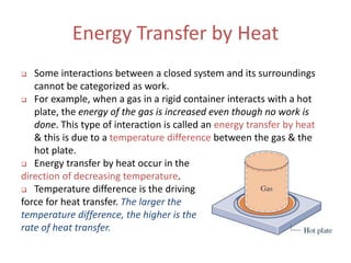
For example, when a gas in a rigid container interacts with a hot
plate, the energy of the gas is increased even though no work is
done. This type of interaction is called an energy transfer by heat
& this is due to a temperature difference between the gas & the
hot plate.
Energy transfer by heat occur in the
direction of decreasing temperature.
Temperature difference is the driving
force for heat transfer. The larger the
temperature difference, the higher is the
rate of heat transfer.
2. Energy transfer by heat: Q (in J)
Q > 0 : heat transfer to the system
Q < 0 : heat transfer from the system
Sign convention for heat transfer is the reverse of work.
Similar to work, the value of heat transfer depends on the process
and not the just the end states, where Q is not a property.
The amount of energy transfer by
heat for a process is given by:
The amount of energy transfer by heat during a period of time can
be found by integrating from time t1 to t2:
where 𝑄 is the net rate of heat transfer.
Sign Convention, Notation & Heat
Transfer Rate
3. The net rate of heat transfer, 𝑄, is related to the heat flux 𝑞 by:
A = area on the system boundary
where heat transfer occurs.
Units of Q & 𝑄 are the same as W and 𝑊, respectively. Units for 𝑞
are those of heat transfer rate per unit area: kW/m2 or Btu/h·ft2.
The word adiabatic means without heat transfer. Thus, if a system
undergoes a process with no heat transfer with its surroundings,
that process is called an adiabatic process.
Sign Convention, Notation & Heat
Transfer Rate
4. Illustration of Fourier’s
conduction law
Heat Transfer Modes
There are three modes of heat transfer (HT):
conduction, convection & radiation
1. Conduction: The transfer of energy from the
more energetic particles of a substance to the
adjacent less energetic ones as a result of
interaction between particles.
Rate of HT by conduction is quantified using
Fourier’s law:
k = thermal conductivity,
property of the material that
indicates the ability to conduct heat. (metals are
good thermal conductors). (Appendix A-19).
• A = area normal to direction of HT
• dT/dx = temperature gradient = (T2 – T1)/L<0
Thus:
5. Illustration of Newton’s law of cooling
Heat Transfer Modes
2. Convection: The transfer of energy between a solid surface at
temperature Tb (shown in figure) & an adjacent fluid that is in
motion & has a temperature Tf, & it involves combined effects of
conduction & fluid motion. (In figure shown heat is transferred
from the surface to the air since Tb >Tf)
Rate of HT by convection is quantified using Newton’s law of
cooling:
• h = HT coefficient (empirical
parameter that depends on the nature
of the flow, fluid properties & geometry)
• A = surface area undergoing HT
6. Heat Transfer Modes
When fans or pumps cause the fluid to move, the value of the HT
coefficient is generally greater than when relatively slow
buoyancy-induced motions occur. Thus, convection can be forced
or natural (free).
Typical values of HT coefficient for forced & free convection:
7. Heat Transfer Modes
3.Radiation: Transfer of energy due to emission of electromagnetic waves or
photons. Unlike conduction, thermal radiation requires no medium to
propagate & can even take place in vacuum. Solid surfaces, gases, & liquids
all emit, absorb, & transmit thermal radiation to varying degrees.
The rate at which energy is emitted from a surface of area A & absolute
temperature Tb is quantified by a modified form of the Stefan–Boltzmann
law:
• ε = emissivity, a surface property that indicates how effectively the
surface radiates & 0 ≤ ε ≤ 1.
• σ = Stefan–Boltzmann constant:
8. Net radiation exchange
Heat Transfer Modes
The net rate of energy transfer by thermal radiation between two surfaces
involves relationships among the properties of the surfaces, their
orientations with respect to each other, the extent to which the intervening
medium scatters, emits, & absorbs thermal radiation, and other factors.
A special case that occurs frequently is radiation exchange between a
surface at temperature Tb and a much larger surrounding surface at Ts, as
shown in figure. The net rate of radiant exchange between the smaller
surface of area A & emissivity ε
& the larger surroundings is:
9. Closing Comments
The first step in a thermodynamic analysis is to define the system & its
boundaries. It is only after this that possible heat interactions with the
surroundings are considered, since these are always evaluated at the
system boundary.
In some cases, Q will be provided in problems. If not, then Q is found
using the energy balance that will be discussed next.
10. Energy Accounting: Energy Balance for
Closed Systems
First law of Thermodynamics (conservation of energy principle):
It states that energy can neither be created nor destroyed during a
process; it can only change forms. Thus it allows for studying the
relationships among the various forms of energy and their interactions.
The energy balance requires that in any process of a closed system the
energy of the system increases or decreases by an amount equal to the
net amount of energy transferred across its boundary:
OR: The signs of Q & W are different, since
+ve Q is heat transfer to system & –W is
work is done on system by surroundings.
11. Energy Accounting: Energy Balance for
Closed Systems
First law of Thermodynamics (conservation of energy principle):
In many cases, the changes in PE & KE for a closed stationary system are
zero, so both ∆KE & ∆PE are = 0.
For all adiabatic processes between two specified states of a closed
system, the net work done is the same regardless of the nature of the
closed system and the details of the process.
For a cyclic process in which a system is changed in several ways but in
the end returns to its original state: the first law tells us that the total
energy of the system must be conserved, meaning that the energy of the
system is the same at the end of the cyclical process as it was at the
beginning. This can be expressed as:
E2 = E1 or E2 - E1 = ∆E = 0
12. Important Aspects of the Energy Balance
The instantaneous time rate form of the energy balance is:
OR:
OR:
All the above are convenient forms of the energy balance to start the
analysis of closed systems.
13. Choices for System Boundaries
Figures show a gas or liquid in a rigid, well-
insulated container:
In Fig. a, the gas itself is the system. As
current flows through the copper plate,
energy transfers from the copper plate
to the gas due to the temperature
difference between the plate & the gas,
& this is called heat transfer.
In Fig. b, the boundary is drawn to
include the copper plate. Thus, from the
thermodynamic definition of work that
the energy transfer that occurs as
current crosses the boundary of this
system must be regarded as work.
14. Choices for System Boundaries
Figure show a gas or liquid in a
rigid, well-insulated container:
In Fig. c, the boundary is
located so that no energy is
transferred across it by heat or
work.
The next two examples illustrate the use of the energy
balance for processes of closed systems.
15. Example-Cooling a Gas in a Piston-Cylinder
Four-tenths kilogram of a certain gas is contained within a
piston–cylinder assembly. The gas undergoes a process for
which the pressure–volume relationship is
pV1.5 = constant
The initial pressure is 3 bar, the initial volume is 0.1 m3, and the
final volume is 0.2 m3. The change in specific internal energy of
the gas in the process is u2 - u1 = -55 kJ/kg. There are no
significant changes in kinetic or potential energy. Determine the
net heat transfer for the process, in kJ.
16. Example-Cooling a Gas in a Piston-Cylinder
SOLUTION
Known: A gas within a piston–cylinder
assembly undergoes an expansion
process for which the pressure–volume
relation and the change in specific
internal energy are specified.
Find: Determine the net heat transfer for
the process.
17. Example-Cooling a Gas in a Piston-Cylinder
Analysis: An energy balance for the closed system takes the form
where the kinetic and potential energy terms drop out by assumption
3. Then, writing ΔU in terms of specific internal energies, the energy
balance becomes
where m is the system mass. Solving for Q
The value of the work for this process is determined in the solution to
part (a) of Example 2.1: W = +17.6 kJ. The change in internal energy is
obtained using given data as
Substituting values
19. Using the Energy Balance: Steady-State
Operation
A system is at steady state if none of its properties change with time.
Many devices operate at steady state or nearly at steady state, so
that property variations with time are small enough to ignore.
The two examples to follow illustrate the application of the energy
rate equation to closed systems at steady state.
20. Example-Evaluating Energy Transfer Rates
of a Gearbox at Steady State
During steady-state operation, a gearbox
receives 60 kW through the input shaft and
delivers power through the output shaft. For
the gearbox as the system, the rate of energy
transfer by convection is
where h = 0.171 kW/m2·K is the heat transfer
coefficient, A = 1.0 m2 is the outer surface area
of the gearbox, Tb = 300 K (27°C) is the
temperature at the outer surface, and Tf = 293
K (20°C) is the temperature of the surrounding
air away from the immediate vicinity of the
gearbox. For the gearbox, evaluate the heat
transfer rate and the power delivered through
the output shaft, each in kW.
21. Example-Evaluating Energy Transfer Rates
of a Gearbox at Steady State
SOLUTION
Known: A gearbox operates at steady state with a known power
input. An expression for the heat transfer rate from the outer surface
is also known.
Find: Determine the heat transfer rate & the power delivered through
the output shaft, each in kW.
Engineering Model:
1. The gearbox is a closed
system at steady state.
2. For the gearbox,
convection is the dominant
heat transfer mode.
22. Example-Evaluating Energy Transfer Rates
of a Gearbox at Steady State
Analysis: Using the given expression for 𝑄 together with known data,
the rate of energy transfer by heat is
❶
The minus sign for 𝑄 signals that energy is carried out of the gearbox
by heat transfer. The energy rate balance, Eq. 2.37, reduces at steady
state to ❷
The symbol 𝑊 represents the net power from the system. The net
power is the sum of 𝑊1 and the output power 𝑊2
23. Example-Evaluating Energy Transfer Rates
of a Gearbox at Steady State
With this expression for 𝑊, the energy rate balance becomes
Solving for 𝑊2, inserting 𝑄= -1.2 kW, and 𝑊1 = -60 kW, where the
minus sign is required because the input shaft brings energy into the
system, we have
❸
❹ The positive sign for 𝑊2 indicates that energy is transferred from
the system through the output shaft, as expected.
25. Example-Determining Surface Temperature
of a Silicon Chip at Steady State
A silicon chip measuring 5 mm on a side & 1 mm
in thickness is embedded in a ceramic substrate.
At steady state, the chip has an electrical power
input of 0.225 W. The top surface of the chip is
exposed to a coolant whose temperature is 20°C.
The heat transfer coefficient for convection
between the chip and the coolant is 150 W/m2·K.
If heat transfer by conduction between the chip
and the substrate is negligible, determine the
surface temperature of the chip, in °C.
26. Example-Determining Surface Temperature
of a Silicon Chip at Steady State
SOLUTION
Known: A silicon chip of known dimensions is exposed on its top
surface to a coolant. The electrical power input and convective heat
transfer coefficient are known.
Find: Determine the surface temperature of the chip at steady state.
Engineering Model:
1. The chip is a closed system at
steady state.
2. There is no heat transfer between
the chip and the substrate.
27. Example-Determining Surface Temperature
of a Silicon Chip at Steady State
Analysis: The surface temperature of the chip, Tb, can be determined
using the energy rate balance, Eq. 2.37, which at steady state reduces
as follows
❶
With assumption 2, the only heat transfer is by convection to the
coolant. In this application, Newton’s law of cooling, Eq. 2.34, takes
the form ❷
Collecting results
Solving for Tb
29. Using the Energy Balance: Transient
Operation
Many devices undergo periods of transient operation where the state
changes with time. (Observed during startup & shutdown periods)
The next example illustrates the application of the energy rate
balance to an electric motor during startup. The example also
involves both electrical work and power transmitted by a shaft.
30. Example-Investigating Transient
Operation of a Motor
The rate of heat transfer between a certain electric motor and its
surroundings varies with time as
where t is in seconds and 𝑄 is in kW. The shaft of the motor rotates at
a constant speed of ω = 100 rad/s (about 955 revolutions per minute,
or RPM) and applies a constant torque of τ = 18 N·m to an external
load. The motor draws a constant electric power input equal to 2.0
kW. For the motor, plot 𝑄 and 𝑊, each in kW, and the change in
energy ΔE, in kJ, as functions of time from t = 0 to t = 120 s. Discuss.
31. Example-Investigating Transient
Operation of a Motor
SOLUTION
Known: A motor operates with constant electric power input, shaft
speed, and applied torque. The time-varying rate of heat transfer
between the motor and its surroundings is given.
Find: Plot 𝑄, 𝑊, and ΔE versus time. Discuss.
Engineering Model:
The system shown in the
Accompanying sketch is a
closed system.
32. Example-Investigating Transient
Operation of a Motor
Analysis: The time rate of change of system energy is
𝑊represents the net power from the system: the sum of the power
associated with the rotating shaft,𝑊𝑠ℎ𝑎𝑓𝑡, and the power associated
with the electricity flow, 𝑊𝑒𝑙𝑒𝑐:
The rate is known from the problem statement: 𝑊𝑒𝑙𝑒𝑐 = -2.0 kW,
where the negative sign is required because energy is carried into the
system by electrical work. The term 𝑊𝑠ℎ𝑎𝑓𝑡 can be evaluated with Eq.
2.20 as
Because energy exits the system along the rotating shaft, this energy
transfer rate is positive. In summary,
where the minus sign means that the electrical power input is greater
than the power transferred out along the shaft.
33. Example-Investigating Transient
Operation of a Motor
With the foregoing result for 𝑊 and the given expression for 𝑄, the energy
rate balance becomes
Integrating
❶ The accompanying plots, Figs. E2.6b and c, are developed using the given expression for 𝑄
and the expressions for 𝑊 and ΔE obtained in the analysis. Because of our sign conventions for
heat and work, the values of 𝑄and 𝑊 are negative. In the first few seconds, the net rate that
energy is carried in by work greatly exceeds the rate that energy is carried out by heat transfer.
Consequently, the energy stored in the motor increases rapidly as the motor “warms up.” As
time elapses, the value of Q approaches 𝑊, and the rate of energy storage diminishes. After
about 100 s, this transient operating mode is nearly over, and there is little further change in
the amount of energy stored, or in any other property. We may say that the motor is then at
steady state. ❷