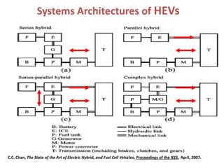
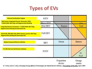
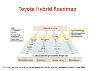
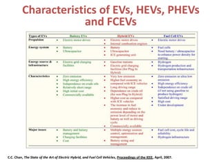
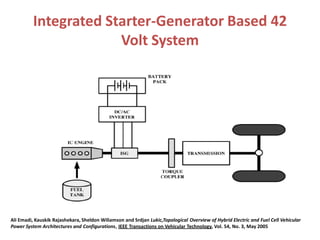
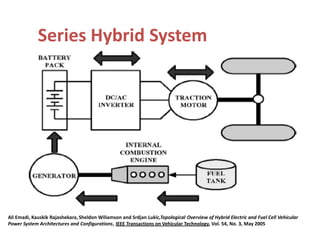
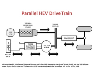
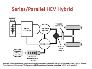
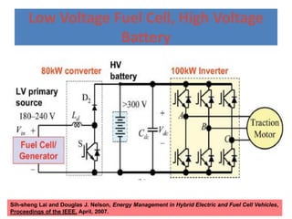
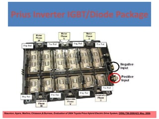
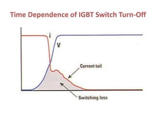
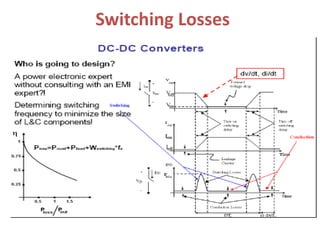
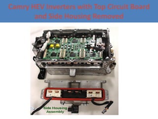
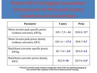
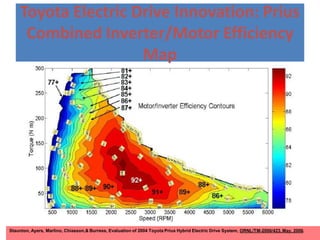
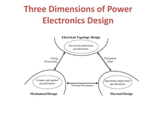
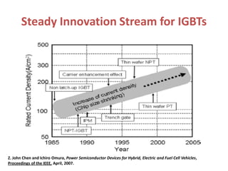
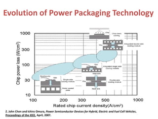
A Tutorial on Hybrid
Electric Vehicles: EV,
HEV, PHEV and FCEV
• Dr. James Gover, IEEE Fellow
Professor of Electrical Engineering
Kettering University
Gasoline Prices Are Driving Commercial
HEV Development
Gerhard Metschies, Pain at the Pump, Foreign Policy, July/August, 2007, p.28.
Nations’ Fuel Standards Are Driving
HEV Development
IEEE Spectrum, September, 2006.
Power Electronics in Hybrid Vehicles
HIGH
VOLTAGE
BATTERY
ELECTRIC
DRIVE MODE
BATTERY
DISCHARGE
REGENERATIVE
BRAKING MODE
BATTERY CHARGE
ELECTRIC
DRIVE MODE
BUCK-BOOST
CONVERTER
REGENERATIVE
BRAKING MODE
BUCK-BOOST
CONVERTER
REGENERATIVE
BRAKING MODE
3 PHASE DIODE
RECTIFIER
ELECTRIC
DRIVE MODE
THREE PHASE
INVERTER
DC-DC
CONVERTER
MOTOR
INVERTER/
RECTIFIER
Energy Flow Diagram for
Series PHEV
ICE
Electric
Generator
Rectifier Battery
120 Volts AC
or 240 Volts
AC External
Power Source
DC to DC
Converter
Three
Phase,
Frequency
Dependent
Inverter
Electric
Motor
Wheel
Systems Architectures of HEVs
C.C. Chan, The State of the Art of Electric Hybrid, and Fuel Cell Vehicles, Proceedings of the IEEE, April, 2007.
Types of EVs
Internal Combustion Engine
Belt Driven Integrated Starter Generator (ISG):
3-5kW With Idle Stop and Regenerative Braking
Integrated Starter Generator: 7-12kW With Idle Stop,
Regenerative Braking & Downsized ICE
30-50 kW, 200-500 Volts With Electric Launch, Idle Stop,
Regenerative Braking & Downsized ICE
Battery Powered Electric Vehicles
75-100 kW Fuel Cell Electric Vehicles
K. T. Chau and C.C. Chan, Emerging Energy-Efficient Technologies for Hybrid Electric Vehicles, Proceedings of the IEEE, April, 2007.
Toyota Hybrid Roadmap
C.C. Chan, The State of the Art of Electric Hybrid, and Fuel Cell Vehicles, Proceedings of the IEEE, April, 2007.
Characteristics of EVs, HEVs, PHEVs
and FCEVs
C.C. Chan, The State of the Art of Electric Hybrid, and Fuel Cell Vehicles, Proceedings of the IEEE, April, 2007.
Integrated Starter-Generator Based 42
Volt System
Ali Emadi, Kauskik Rajashekara, Sheldon Wiliamson and Srdjan Lukic,Topological Overview of Hybrid Electric and Fuel Cell Vehicular
Power System Architectures and Configurations, IEEE Transactions on Vehicular Technology, Vol. 54, No. 3, May 2005
Series Hybrid System
Ali Emadi, Kauskik Rajashekara, Sheldon Wiliamson and Srdjan Lukic,Topological Overview of Hybrid Electric and Fuel Cell Vehicular
Power System Architectures and Configurations, IEEE Transactions on Vehicular Technology, Vol. 54, No. 3, May 2005
Parallel HEV DriveTrain
Ali Emadi, Kauskik Rajashekara, Sheldon Wiliamson and Srdjan Lukic,Topological Overview of Hybrid Electric and Fuel Cell Vehicular
Power System Architectures and Configurations, IEEE Transactions on Vehicular Technology, Vol. 54, No. 3, May 2005
Series/Parallel HEV Hybrid
Ali Emadi, Kauskik Rajashekara, Sheldon Wiliamson and Srdjan Lukic,Topological Overview of Hybrid Electric and Fuel Cell Vehicular
Power System Architectures and Configurations, IEEE Transactions on Vehicular Technology, Vol. 54, No. 3, May 2005
Planetary Gear Set
Mehrdad Ehsani, Yimin Gao, and John M. Miller, Hybrid Electric Vehicles: Architecture and Motor Drives, Proceedings of the IEEE, April, 2007.
FCEV & PHEV Volt Concepts
FCEV Option
PHEV Option
Fuel
Cell
Small
Battery
ICE
Large
Battery
Hydrogen Tanks
Fuel Tanks
Escape Hybrid Transaxle Cut-Away
Transaxle Control
Module
Planetary Gearset
High Voltage
Connector
Stefan Pototschnik, Overview of the Ford Escape Hybrid, Sept. 12, 2006, Kettering University.
Integration of PHEVs On Grid
Mehdi Ferdowski, Plug-in Hybrid Vehicles – A vision for the Future, 2007 IEEE VPPPC
POWER LINE TRANSIENTS
Night Electricity Is the Fuel for PHEV
Source: EPRI
Thomas Schneider, Transportation Efficiency Through Electric Drives and the Power Grid, Capitol Hill Forum,
Plug-in Hybrid Electric Vehicles: Towards Energy Independence, July 10, 2007.
PHEV Energy Storage Used for Power Peaking
PHEV USE
Harold Adams, Planning Considerations for a Carbon Constrained Grid, 10/2007
EPRI Assumptions for New Car US Sales
Two Battery Types Are Preferred for
Hybrid-Electric Vehicles
• Nickel Metal Hydride (NiMH)
– Introduced near end of 20th century
– Similar performance to NiCad battery but its energy and power densities are
higher and it charges faster
– The metals into which hydrogen is adsorbed are proprietary
– The battery cell must be sealed in order to keep air from reacting with the
hydride
– Battery can require cooling if charged fast
• Lithium Ion
– Introduced in early 1990s.
– Precise voltage control is needed when charging battery because if too high,
battery can be damaged and if too low, battery will be undercharged
– Because of its considerable weight advantage over other battery types, it is
highly attractive for future hybrid electric vehicles
– Large batteries are prohibitively expensive
NiMH Battery Discharge Reactions
H2 + M MH2
H2 + 2OH
-
2H2O + 2e
-
K
+
+ H2O OH
-
2NiO(OH)+2H2O +2e
-
2Ni(OH)2 + 2OH
-
Load
Metal alloy sponge that absorbs and then gives back hydrogen
Charge Flow in Li-Ion Battery
Steven Vance, Parallel-Cell Connection in Lithium-Ion Battery, Kettering University Senior Thesis, 12/08
Hysteresis Effect in NiMH Battery Cell
Steven Vance, Parallel-Cell Connection in Lithium-Ion Battery, Kettering University Senior Thesis, 12/08
Comparison of Performance of
Battery Types Used in HEV
Andrew F. Burke, Batteries and Ultracapacitors for Electric, Hybrid, and Fuel Cell Vehicles, Proceedings of the IEEE,
April, 2007.
Battery Power as Function of
Temperature
Steven Vance, Parallel-Cell Connection in Lithium-Ion Battery, Kettering UniversitySenior Thesis, 12/08
Effect of Temperature on NiMH
Battery Performance
L. Serraro, Z. Chehab, Y. Guezennec and G. Rizzoni, An Aging Model fo NI-MH Batteries for Hybrid Electric
Vehicles, IEEE VTS Vehicle Power and Propulsion Conference, July, 2005.
Dependence of NiMH Cycle Life on
Depth of Discharge
L. Serraro, Z. Chehab, Y. Guezennec and G. Rizzoni, An Aging Model fo NI-MH Batteries for Hybrid Electric
Vehicles, IEEE VTS Vehicle Power and Propulsion Conference, July, 2005.
Ultracapacitors Reduce Battery Surge
Currents and Increase Battery Life
Andrew F. Burke, Batteries and Ultracapacitors for Electric, Hybrid, and Fuel Cell Vehicles, Proceedings of the IEEE,
April, 2007.
Packaging of Prius Power Electronics
Staunton, Ayers, Marlino, Chiasson,& Burress, Evaluation of 2004 Toyota Prius Hybrid Electric Drive System, ORNL/TM-2006/423, May, 2006.
Buck-Boost DC-DC Converter-
Continuous Mode
Switch Closed Switch Open
f
RD
L
RCf
D
V
V
D
D
V
V
o
o
s
o
2
)1(
1
2
min
Hart, p. 201
Note
Ripple
Voltage
Inverter Schematic
Low Voltage Battery, High Voltage
Fuel Cell
Sih-sheng Lai and Douglas J. Nelson, Energy Management in Hybrid Electric and Fuel Cell Vehicles,
Proceedings of the IEEE, April, 2007.
Low Voltage Fuel Cell, High Voltage
Battery
Sih-sheng Lai and Douglas J. Nelson, Energy Management in Hybrid Electric and Fuel Cell Vehicles,
Proceedings of the IEEE, April, 2007.
Prius Inverter IGBT/Diode Package
Staunton, Ayers, Marlino, Chiasson,& Burress, Evaluation of 2004 Toyota Prius Hybrid Electric Drive System, ORNL/TM-2006/423, May, 2006.
Time Dependence of IGBT Switch Turn-Off
Switching Losses
Heat Removal Mechanisms from Chip
Without Special Cooling
PRINTED WIRING BOARD
HEAT SINKSUBSTRATE
CHIP
CONVECTION
CONDUCTION
RADIATION
In ICs with conventional packaging, the heat generation is at the top surface
of the chip.
Prius Inverter IGBT/Diode Package
Staunton, Ayers, Marlino, Chiasson,& Burress, Evaluation of 2004 Toyota Prius Hybrid Electric Drive System, ORNL/TM-2006/423, May, 2006.
IGBT-Diode Pair
Staunton, Ayers, Marlino, Chiasson,& Burress, Evaluation of 2004 Toyota Prius Hybrid Electric Drive System, ORNL/TM-2006/423, May, 2006.
Overview of Packaging in Prius
Inverter/Converter
Staunton, Ayers, Marlino, Chiasson,& Burress, Evaluation of 2004 Toyota Prius Hybrid Electric Drive System, ORNL/TM-2006/423, May, 2006.
Toyota Camry Hybrid Integrated
Power Module
Camry HEV Inverters with Top Circuit Board
and Side Housing Removed
Toyota HEV Packaging Innovation:
Comparison of Prius and Camry
Inverters and Converters
Parameter Camry Prius
Motor inverter peak specific power
(without converter), kW/kg 105/~7.5=~14 50/8.8= 5.7
Motor inverter peak power density
(without converter), kW/L 105/~6 =~17.5 50/8.7=5.7
Buck/boost converter specific power,
kW/kg 30/~7.6=~3.9 20/4.8=4.2
Buck/boost converter power density,
kW/L 30/2.9=10 20/5.9=3.41
1 This low converter power density is largely the result of the non-optimal packaging of
the converter filter capacitor in the Prius inverter/converter housing
Toyota Electric Drive Innovation: Prius
Combined Inverter/Motor Efficiency
Map
Staunton, Ayers, Marlino, Chiasson,& Burress, Evaluation of 2004 Toyota Prius Hybrid Electric Drive System, ORNL/TM-2006/423, May, 2006.
Three Dimensions of Power
Electronics Design
Steady Innovation Stream for IGBTs
Z. John Chen and Ichiro Omura, Power Semiconductor Devices for Hybrid, Electric and Fuel Cell Vehicles,
Proceedings of the IEEE, April, 2007.
Evolution of Power Packaging Technology
Z. John Chen and Ichiro Omura, Power Semiconductor Devices for Hybrid, Electric and Fuel Cell Vehicles,
Proceedings of the IEEE, April, 2007.
Cross-Section of Normally-On Ion-
Implanted SiC VJFET.
0.19 Square Cm VJFETs Fabricated on
a 3-Inch 4H-SiC Wafer
Power Electronics Noise in
Hybrid Vehicles
HIGH
VOLTAGE
BATTERY
ELECTRIC
DRIVE MODE
BATTERY
DISCHARGE
REGENERATIVE
BRAKING MODE
BATTERY CHARGE
ELECTRIC
DRIVE MODE
BUCK-BOOST
CONVERTER
REGENERATIVE
BRAKING MODE
BUCK-BOOST
CONVERTER
REGENERATIVE
BRAKING MODE
3 PHASE DIODE
RECTIFIER
ELECTRIC
DRIVE MODE
THREE PHASE
INVERTER
DC-DC
CONVERTER
MOTOR
INVERTER/
RECTIFIER
NOISE SOURCES
Inverter Common Mode Noise
Firuz Zare, EMC and Modern Power Electronics, Tutorial, 2007 IEEE International Symposium on EMC
Noise Spectrum Due to IGBT or
MOSFET Switching in Power
Electronics
''
T
A
]
2
'
2
'
][
2
)
2
(
[
2
T
n
T
n
Sin
T
n
T
n
Sin
T
A
Cn
Frequency Spectrum of an
Ideal Trapezoid Signal
Trapezoid signal amplitude = 1, Frequency = 20kHz, Rise time = Fall time = 400ns = tau, full width at
half max of current = 25 microseconds = t0.
F. Costa and D. Magnon, Graphical Analysis of the Spectra of EMI Sources in Power Electronics, IEEE Transactions on Power Electronics,
Vol. 20, No. 6, Nov. 2005.
Electrical Behavior of Ball Bearings
Firuz Zare, EMC and Modern Power Electronics, Tutorial, 2007 IEEE International Symposium on EMC
Effects of Inverter
Generated Common Mode
Noise on Motors
• Leakage Currents or Bearing Current Going to
Ground Through Stray Capacitance Between Stator
and Rotor Can Create Skin Currents on Auto Body.
(Very low impedance at high frequency.)
– Want CM return currents to flow on cable shield so no
external electromagnetic field generated.
• Shortened Insulation Lifetime of Stator Windings.
• Pitting of Bearings.

Híbrido Toyota

  • 1.
    A Tutorial onHybrid Electric Vehicles: EV, HEV, PHEV and FCEV • Dr. James Gover, IEEE Fellow Professor of Electrical Engineering Kettering University
  • 2.
    Gasoline Prices AreDriving Commercial HEV Development Gerhard Metschies, Pain at the Pump, Foreign Policy, July/August, 2007, p.28.
  • 3.
    Nations’ Fuel StandardsAre Driving HEV Development IEEE Spectrum, September, 2006.
  • 4.
    Power Electronics inHybrid Vehicles HIGH VOLTAGE BATTERY ELECTRIC DRIVE MODE BATTERY DISCHARGE REGENERATIVE BRAKING MODE BATTERY CHARGE ELECTRIC DRIVE MODE BUCK-BOOST CONVERTER REGENERATIVE BRAKING MODE BUCK-BOOST CONVERTER REGENERATIVE BRAKING MODE 3 PHASE DIODE RECTIFIER ELECTRIC DRIVE MODE THREE PHASE INVERTER DC-DC CONVERTER MOTOR INVERTER/ RECTIFIER
  • 5.
    Energy Flow Diagramfor Series PHEV ICE Electric Generator Rectifier Battery 120 Volts AC or 240 Volts AC External Power Source DC to DC Converter Three Phase, Frequency Dependent Inverter Electric Motor Wheel
  • 6.
    Systems Architectures ofHEVs C.C. Chan, The State of the Art of Electric Hybrid, and Fuel Cell Vehicles, Proceedings of the IEEE, April, 2007.
  • 7.
    Types of EVs InternalCombustion Engine Belt Driven Integrated Starter Generator (ISG): 3-5kW With Idle Stop and Regenerative Braking Integrated Starter Generator: 7-12kW With Idle Stop, Regenerative Braking & Downsized ICE 30-50 kW, 200-500 Volts With Electric Launch, Idle Stop, Regenerative Braking & Downsized ICE Battery Powered Electric Vehicles 75-100 kW Fuel Cell Electric Vehicles K. T. Chau and C.C. Chan, Emerging Energy-Efficient Technologies for Hybrid Electric Vehicles, Proceedings of the IEEE, April, 2007.
  • 8.
    Toyota Hybrid Roadmap C.C.Chan, The State of the Art of Electric Hybrid, and Fuel Cell Vehicles, Proceedings of the IEEE, April, 2007.
  • 9.
    Characteristics of EVs,HEVs, PHEVs and FCEVs C.C. Chan, The State of the Art of Electric Hybrid, and Fuel Cell Vehicles, Proceedings of the IEEE, April, 2007.
  • 10.
    Integrated Starter-Generator Based42 Volt System Ali Emadi, Kauskik Rajashekara, Sheldon Wiliamson and Srdjan Lukic,Topological Overview of Hybrid Electric and Fuel Cell Vehicular Power System Architectures and Configurations, IEEE Transactions on Vehicular Technology, Vol. 54, No. 3, May 2005
  • 11.
    Series Hybrid System AliEmadi, Kauskik Rajashekara, Sheldon Wiliamson and Srdjan Lukic,Topological Overview of Hybrid Electric and Fuel Cell Vehicular Power System Architectures and Configurations, IEEE Transactions on Vehicular Technology, Vol. 54, No. 3, May 2005
  • 12.
    Parallel HEV DriveTrain AliEmadi, Kauskik Rajashekara, Sheldon Wiliamson and Srdjan Lukic,Topological Overview of Hybrid Electric and Fuel Cell Vehicular Power System Architectures and Configurations, IEEE Transactions on Vehicular Technology, Vol. 54, No. 3, May 2005
  • 13.
    Series/Parallel HEV Hybrid AliEmadi, Kauskik Rajashekara, Sheldon Wiliamson and Srdjan Lukic,Topological Overview of Hybrid Electric and Fuel Cell Vehicular Power System Architectures and Configurations, IEEE Transactions on Vehicular Technology, Vol. 54, No. 3, May 2005
  • 14.
    Planetary Gear Set MehrdadEhsani, Yimin Gao, and John M. Miller, Hybrid Electric Vehicles: Architecture and Motor Drives, Proceedings of the IEEE, April, 2007.
  • 15.
    FCEV & PHEVVolt Concepts FCEV Option PHEV Option Fuel Cell Small Battery ICE Large Battery Hydrogen Tanks Fuel Tanks
  • 16.
    Escape Hybrid TransaxleCut-Away Transaxle Control Module Planetary Gearset High Voltage Connector Stefan Pototschnik, Overview of the Ford Escape Hybrid, Sept. 12, 2006, Kettering University.
  • 17.
    Integration of PHEVsOn Grid Mehdi Ferdowski, Plug-in Hybrid Vehicles – A vision for the Future, 2007 IEEE VPPPC POWER LINE TRANSIENTS
  • 18.
    Night Electricity Isthe Fuel for PHEV Source: EPRI Thomas Schneider, Transportation Efficiency Through Electric Drives and the Power Grid, Capitol Hill Forum, Plug-in Hybrid Electric Vehicles: Towards Energy Independence, July 10, 2007.
  • 19.
    PHEV Energy StorageUsed for Power Peaking PHEV USE Harold Adams, Planning Considerations for a Carbon Constrained Grid, 10/2007
  • 20.
    EPRI Assumptions forNew Car US Sales
  • 21.
    Two Battery TypesAre Preferred for Hybrid-Electric Vehicles • Nickel Metal Hydride (NiMH) – Introduced near end of 20th century – Similar performance to NiCad battery but its energy and power densities are higher and it charges faster – The metals into which hydrogen is adsorbed are proprietary – The battery cell must be sealed in order to keep air from reacting with the hydride – Battery can require cooling if charged fast • Lithium Ion – Introduced in early 1990s. – Precise voltage control is needed when charging battery because if too high, battery can be damaged and if too low, battery will be undercharged – Because of its considerable weight advantage over other battery types, it is highly attractive for future hybrid electric vehicles – Large batteries are prohibitively expensive
  • 22.
    NiMH Battery DischargeReactions H2 + M MH2 H2 + 2OH - 2H2O + 2e - K + + H2O OH - 2NiO(OH)+2H2O +2e - 2Ni(OH)2 + 2OH - Load Metal alloy sponge that absorbs and then gives back hydrogen
  • 23.
    Charge Flow inLi-Ion Battery Steven Vance, Parallel-Cell Connection in Lithium-Ion Battery, Kettering University Senior Thesis, 12/08
  • 24.
    Hysteresis Effect inNiMH Battery Cell Steven Vance, Parallel-Cell Connection in Lithium-Ion Battery, Kettering University Senior Thesis, 12/08
  • 25.
    Comparison of Performanceof Battery Types Used in HEV Andrew F. Burke, Batteries and Ultracapacitors for Electric, Hybrid, and Fuel Cell Vehicles, Proceedings of the IEEE, April, 2007.
  • 26.
    Battery Power asFunction of Temperature Steven Vance, Parallel-Cell Connection in Lithium-Ion Battery, Kettering UniversitySenior Thesis, 12/08
  • 27.
    Effect of Temperatureon NiMH Battery Performance L. Serraro, Z. Chehab, Y. Guezennec and G. Rizzoni, An Aging Model fo NI-MH Batteries for Hybrid Electric Vehicles, IEEE VTS Vehicle Power and Propulsion Conference, July, 2005.
  • 28.
    Dependence of NiMHCycle Life on Depth of Discharge L. Serraro, Z. Chehab, Y. Guezennec and G. Rizzoni, An Aging Model fo NI-MH Batteries for Hybrid Electric Vehicles, IEEE VTS Vehicle Power and Propulsion Conference, July, 2005.
  • 29.
    Ultracapacitors Reduce BatterySurge Currents and Increase Battery Life Andrew F. Burke, Batteries and Ultracapacitors for Electric, Hybrid, and Fuel Cell Vehicles, Proceedings of the IEEE, April, 2007.
  • 30.
    Packaging of PriusPower Electronics Staunton, Ayers, Marlino, Chiasson,& Burress, Evaluation of 2004 Toyota Prius Hybrid Electric Drive System, ORNL/TM-2006/423, May, 2006.
  • 31.
    Buck-Boost DC-DC Converter- ContinuousMode Switch Closed Switch Open f RD L RCf D V V D D V V o o s o 2 )1( 1 2 min Hart, p. 201 Note Ripple Voltage
  • 32.
  • 33.
    Low Voltage Battery,High Voltage Fuel Cell Sih-sheng Lai and Douglas J. Nelson, Energy Management in Hybrid Electric and Fuel Cell Vehicles, Proceedings of the IEEE, April, 2007.
  • 34.
    Low Voltage FuelCell, High Voltage Battery Sih-sheng Lai and Douglas J. Nelson, Energy Management in Hybrid Electric and Fuel Cell Vehicles, Proceedings of the IEEE, April, 2007.
  • 35.
    Prius Inverter IGBT/DiodePackage Staunton, Ayers, Marlino, Chiasson,& Burress, Evaluation of 2004 Toyota Prius Hybrid Electric Drive System, ORNL/TM-2006/423, May, 2006.
  • 36.
    Time Dependence ofIGBT Switch Turn-Off
  • 37.
  • 38.
    Heat Removal Mechanismsfrom Chip Without Special Cooling PRINTED WIRING BOARD HEAT SINKSUBSTRATE CHIP CONVECTION CONDUCTION RADIATION In ICs with conventional packaging, the heat generation is at the top surface of the chip.
  • 39.
    Prius Inverter IGBT/DiodePackage Staunton, Ayers, Marlino, Chiasson,& Burress, Evaluation of 2004 Toyota Prius Hybrid Electric Drive System, ORNL/TM-2006/423, May, 2006.
  • 40.
    IGBT-Diode Pair Staunton, Ayers,Marlino, Chiasson,& Burress, Evaluation of 2004 Toyota Prius Hybrid Electric Drive System, ORNL/TM-2006/423, May, 2006.
  • 41.
    Overview of Packagingin Prius Inverter/Converter Staunton, Ayers, Marlino, Chiasson,& Burress, Evaluation of 2004 Toyota Prius Hybrid Electric Drive System, ORNL/TM-2006/423, May, 2006.
  • 42.
    Toyota Camry HybridIntegrated Power Module
  • 43.
    Camry HEV Inverterswith Top Circuit Board and Side Housing Removed
  • 44.
    Toyota HEV PackagingInnovation: Comparison of Prius and Camry Inverters and Converters Parameter Camry Prius Motor inverter peak specific power (without converter), kW/kg 105/~7.5=~14 50/8.8= 5.7 Motor inverter peak power density (without converter), kW/L 105/~6 =~17.5 50/8.7=5.7 Buck/boost converter specific power, kW/kg 30/~7.6=~3.9 20/4.8=4.2 Buck/boost converter power density, kW/L 30/2.9=10 20/5.9=3.41 1 This low converter power density is largely the result of the non-optimal packaging of the converter filter capacitor in the Prius inverter/converter housing
  • 45.
    Toyota Electric DriveInnovation: Prius Combined Inverter/Motor Efficiency Map Staunton, Ayers, Marlino, Chiasson,& Burress, Evaluation of 2004 Toyota Prius Hybrid Electric Drive System, ORNL/TM-2006/423, May, 2006.
  • 46.
    Three Dimensions ofPower Electronics Design
  • 47.
    Steady Innovation Streamfor IGBTs Z. John Chen and Ichiro Omura, Power Semiconductor Devices for Hybrid, Electric and Fuel Cell Vehicles, Proceedings of the IEEE, April, 2007.
  • 48.
    Evolution of PowerPackaging Technology Z. John Chen and Ichiro Omura, Power Semiconductor Devices for Hybrid, Electric and Fuel Cell Vehicles, Proceedings of the IEEE, April, 2007.
  • 49.
    Cross-Section of Normally-OnIon- Implanted SiC VJFET.
  • 50.
    0.19 Square CmVJFETs Fabricated on a 3-Inch 4H-SiC Wafer
  • 51.
    Power Electronics Noisein Hybrid Vehicles HIGH VOLTAGE BATTERY ELECTRIC DRIVE MODE BATTERY DISCHARGE REGENERATIVE BRAKING MODE BATTERY CHARGE ELECTRIC DRIVE MODE BUCK-BOOST CONVERTER REGENERATIVE BRAKING MODE BUCK-BOOST CONVERTER REGENERATIVE BRAKING MODE 3 PHASE DIODE RECTIFIER ELECTRIC DRIVE MODE THREE PHASE INVERTER DC-DC CONVERTER MOTOR INVERTER/ RECTIFIER NOISE SOURCES
  • 52.
    Inverter Common ModeNoise Firuz Zare, EMC and Modern Power Electronics, Tutorial, 2007 IEEE International Symposium on EMC
  • 53.
    Noise Spectrum Dueto IGBT or MOSFET Switching in Power Electronics '' T A ] 2 ' 2 ' ][ 2 ) 2 ( [ 2 T n T n Sin T n T n Sin T A Cn
  • 54.
    Frequency Spectrum ofan Ideal Trapezoid Signal Trapezoid signal amplitude = 1, Frequency = 20kHz, Rise time = Fall time = 400ns = tau, full width at half max of current = 25 microseconds = t0. F. Costa and D. Magnon, Graphical Analysis of the Spectra of EMI Sources in Power Electronics, IEEE Transactions on Power Electronics, Vol. 20, No. 6, Nov. 2005.
  • 55.
    Electrical Behavior ofBall Bearings Firuz Zare, EMC and Modern Power Electronics, Tutorial, 2007 IEEE International Symposium on EMC
  • 56.
    Effects of Inverter GeneratedCommon Mode Noise on Motors • Leakage Currents or Bearing Current Going to Ground Through Stray Capacitance Between Stator and Rotor Can Create Skin Currents on Auto Body. (Very low impedance at high frequency.) – Want CM return currents to flow on cable shield so no external electromagnetic field generated. • Shortened Insulation Lifetime of Stator Windings. • Pitting of Bearings.