Here is a summary of the key points from the course overview:
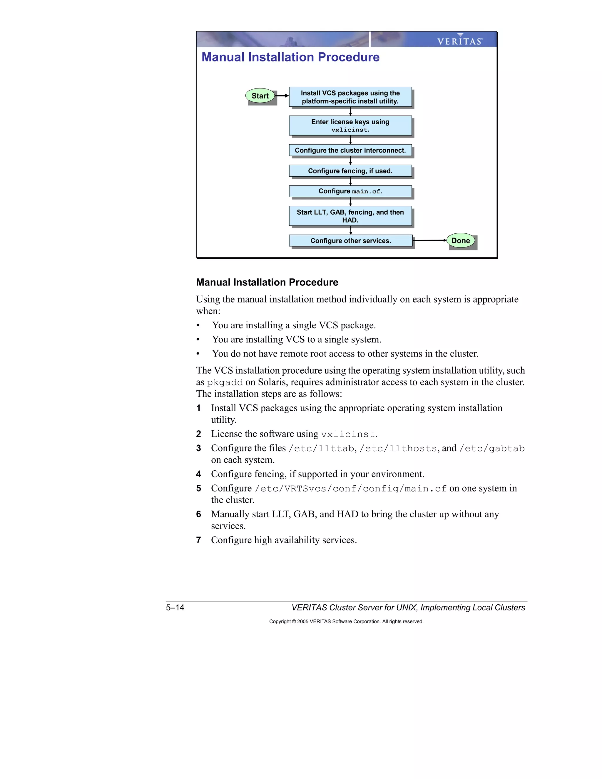
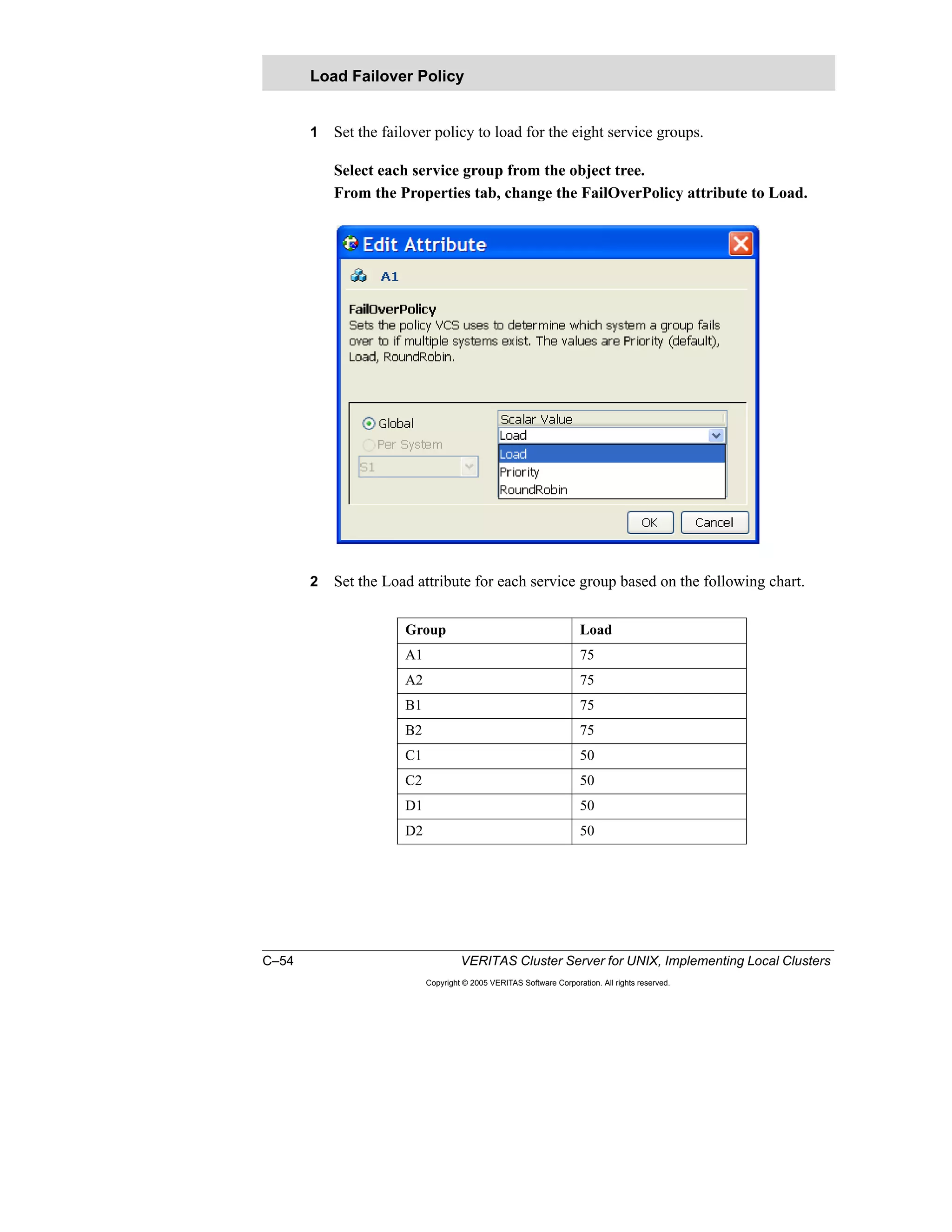
- This course builds upon the fundamentals covered in the VERITAS Cluster Server Fundamentals course and focuses on implementing more complex cluster configurations with VCS.
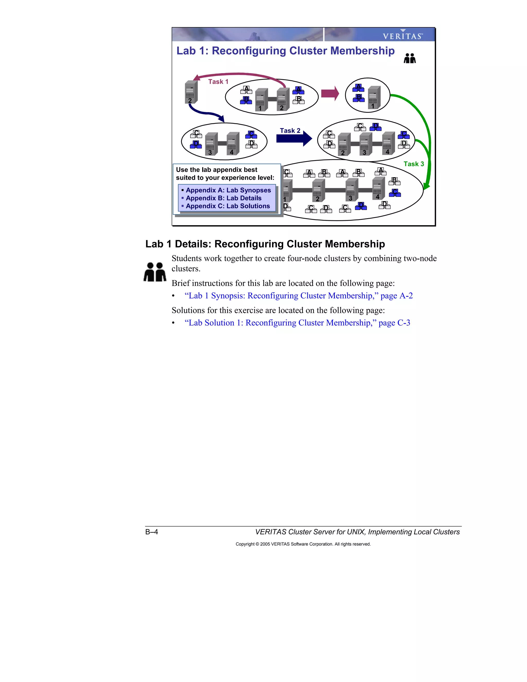
- Participants will simulate real-world tasks of configuring advanced cluster features through hands-on labs that build upon each other.
- Core lessons cover the most common cluster implementations, while other lessons illustrate additional VCS capabilities through alternative configurations.
- The overall goal is to provide expertise in applying best practices for implementing any VCS design based on a provided high availability design that is used as an example throughout the course labs.
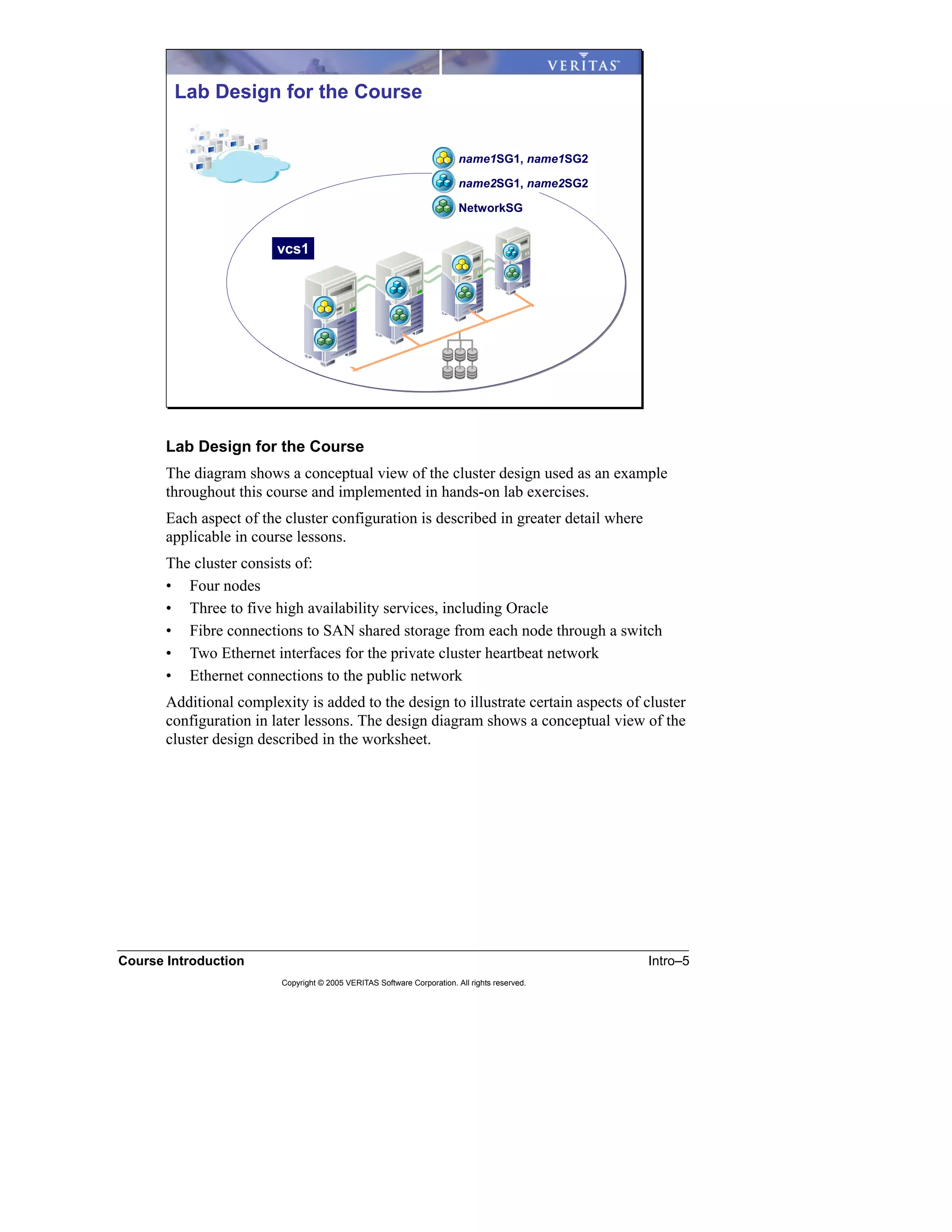
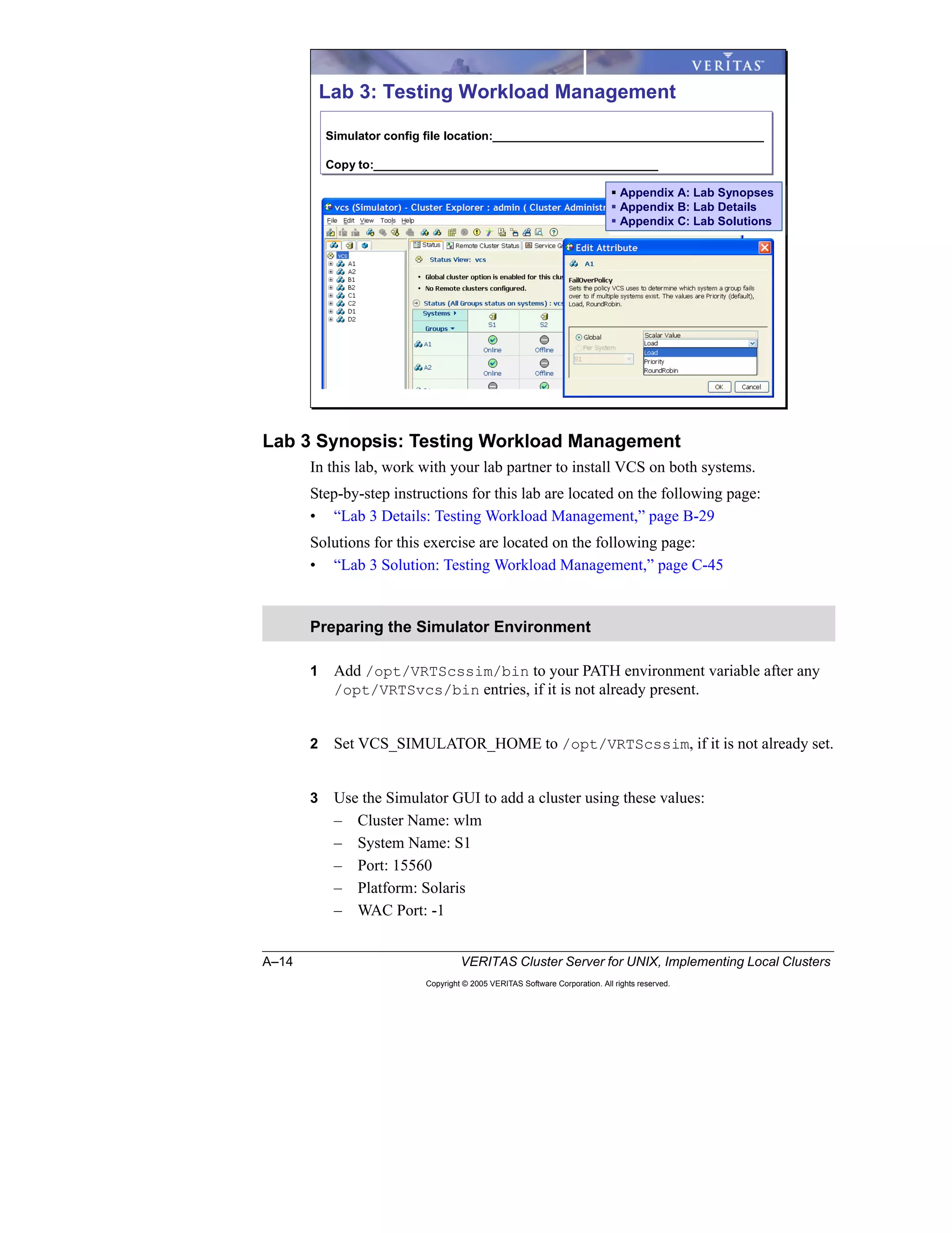
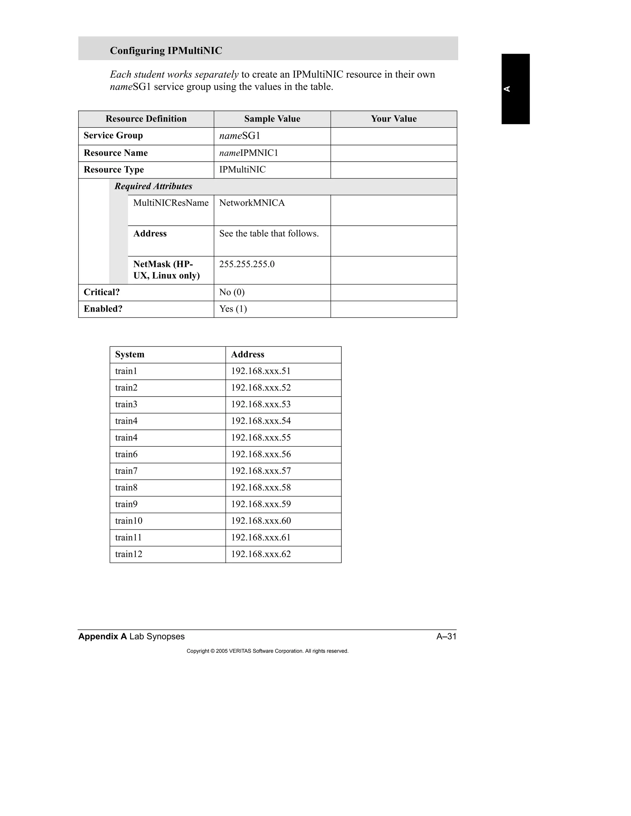
- Hands-on labs use a conceptual cluster design consisting of


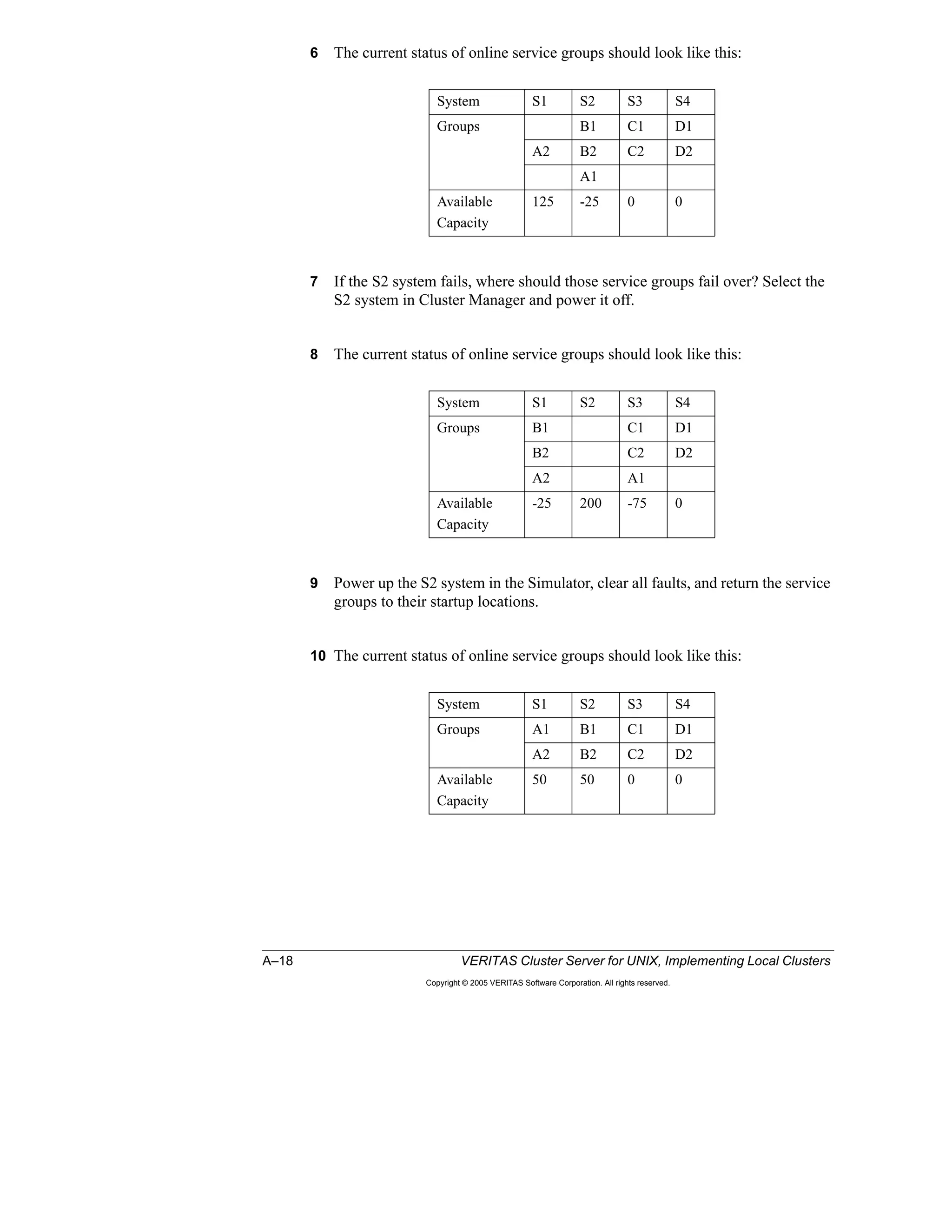
![Lesson 3 Workload Management 3–17
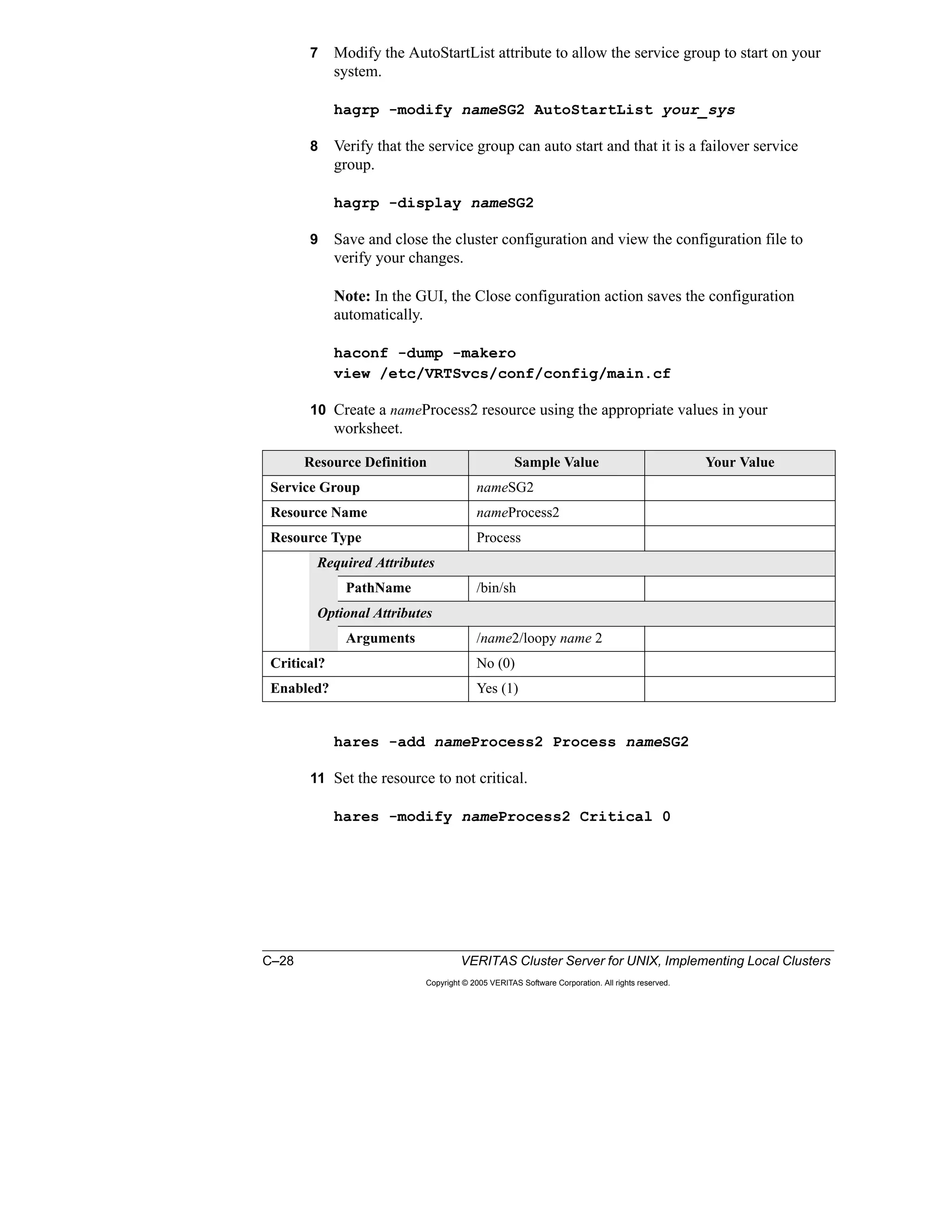
Copyright © 2005 VERITAS Software Corporation. All rights reserved.
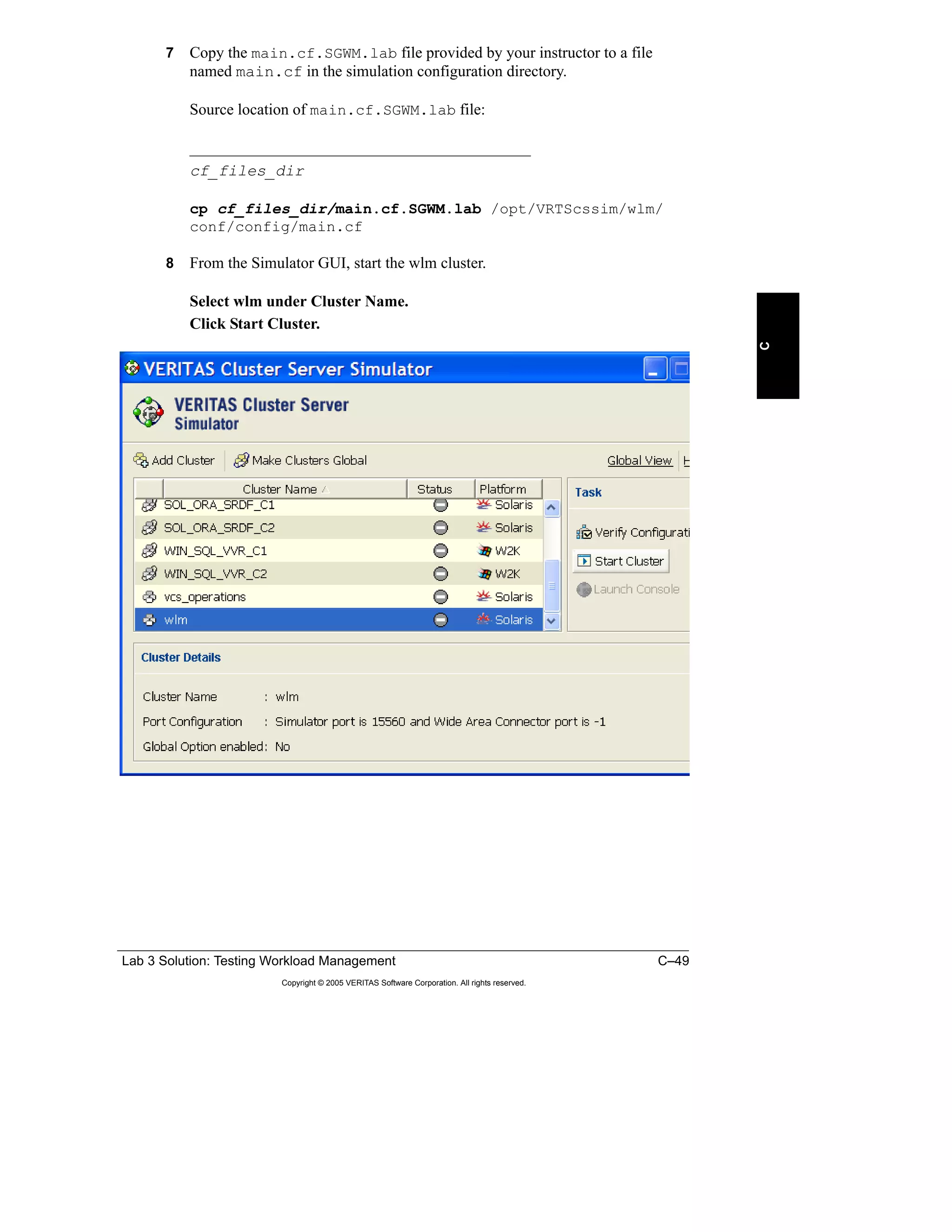
3
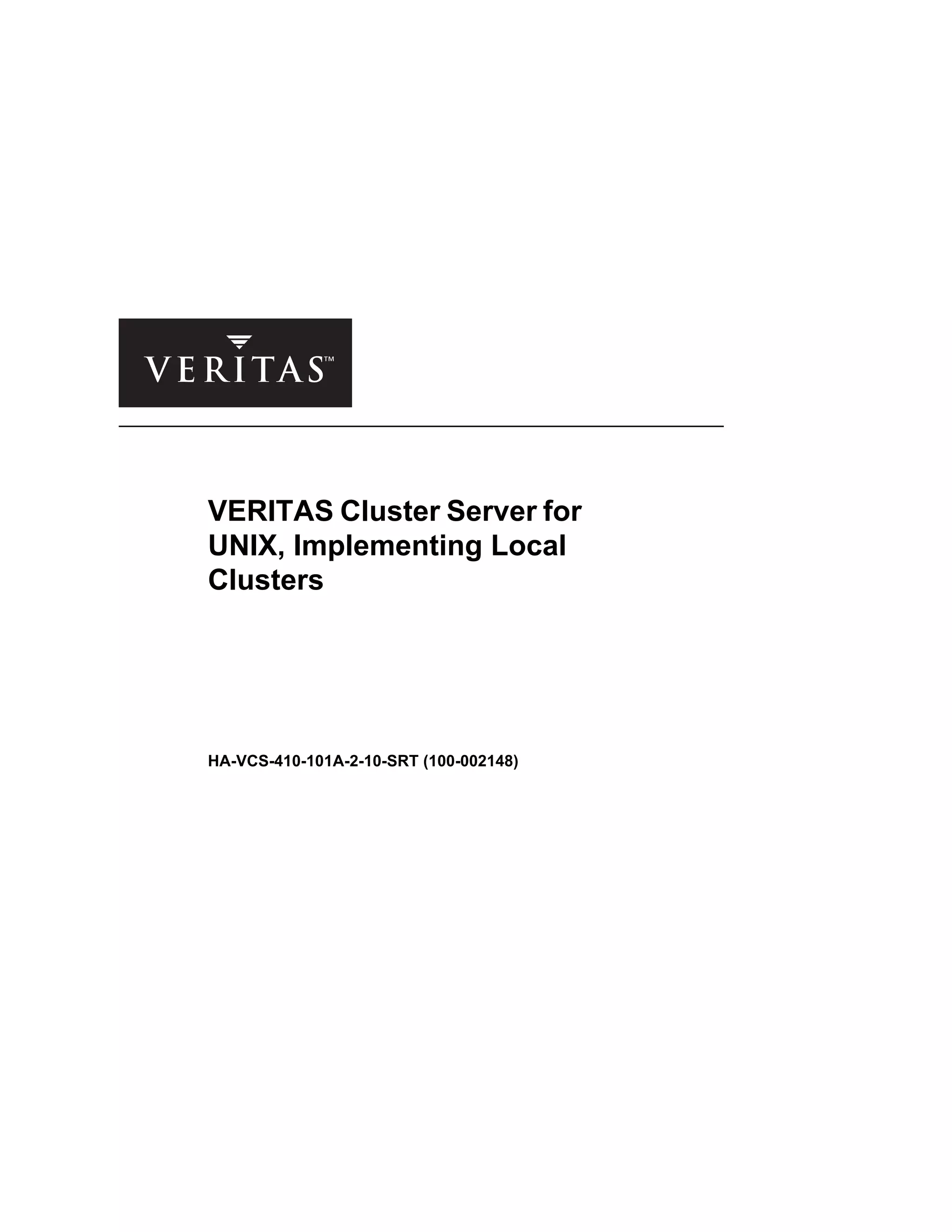
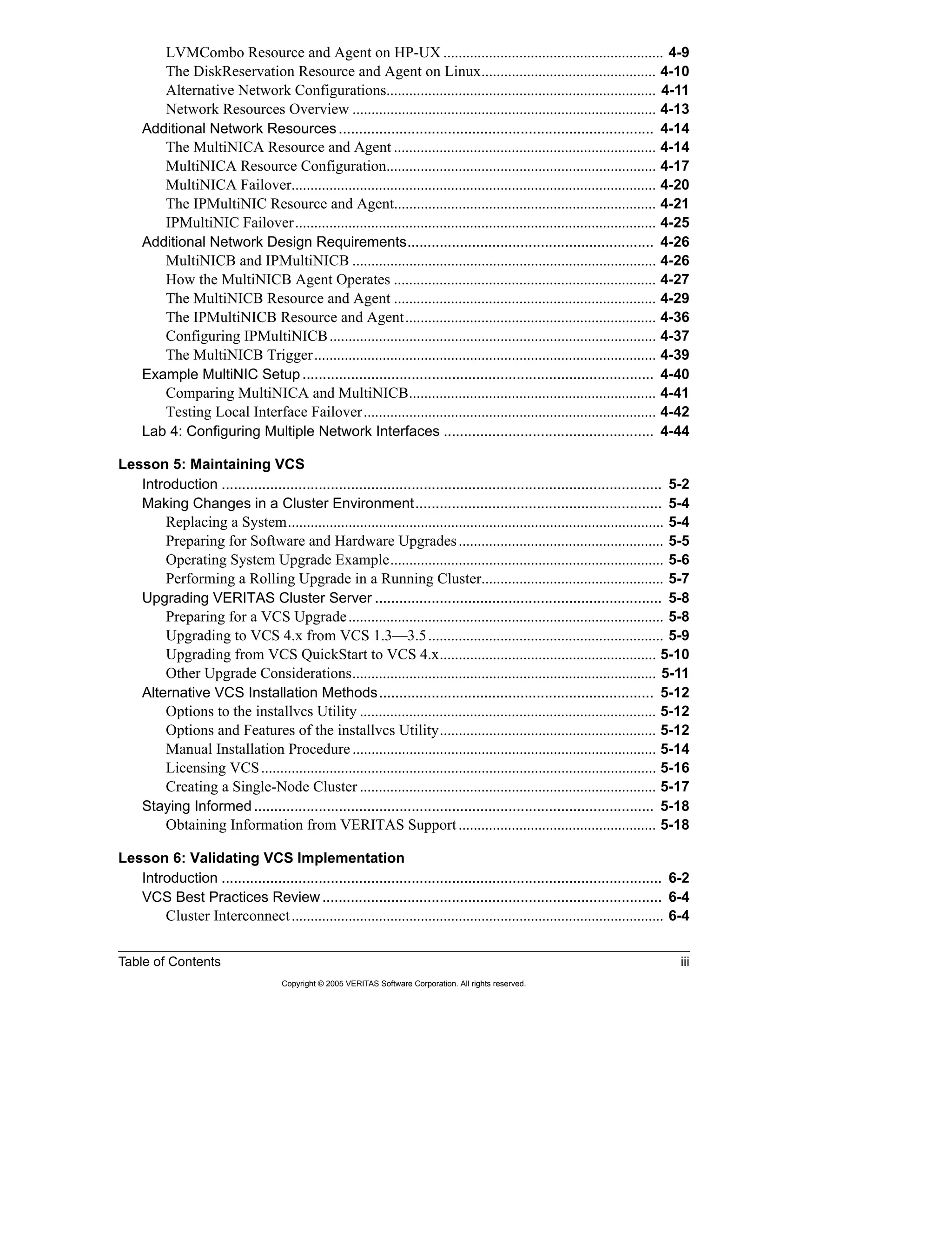
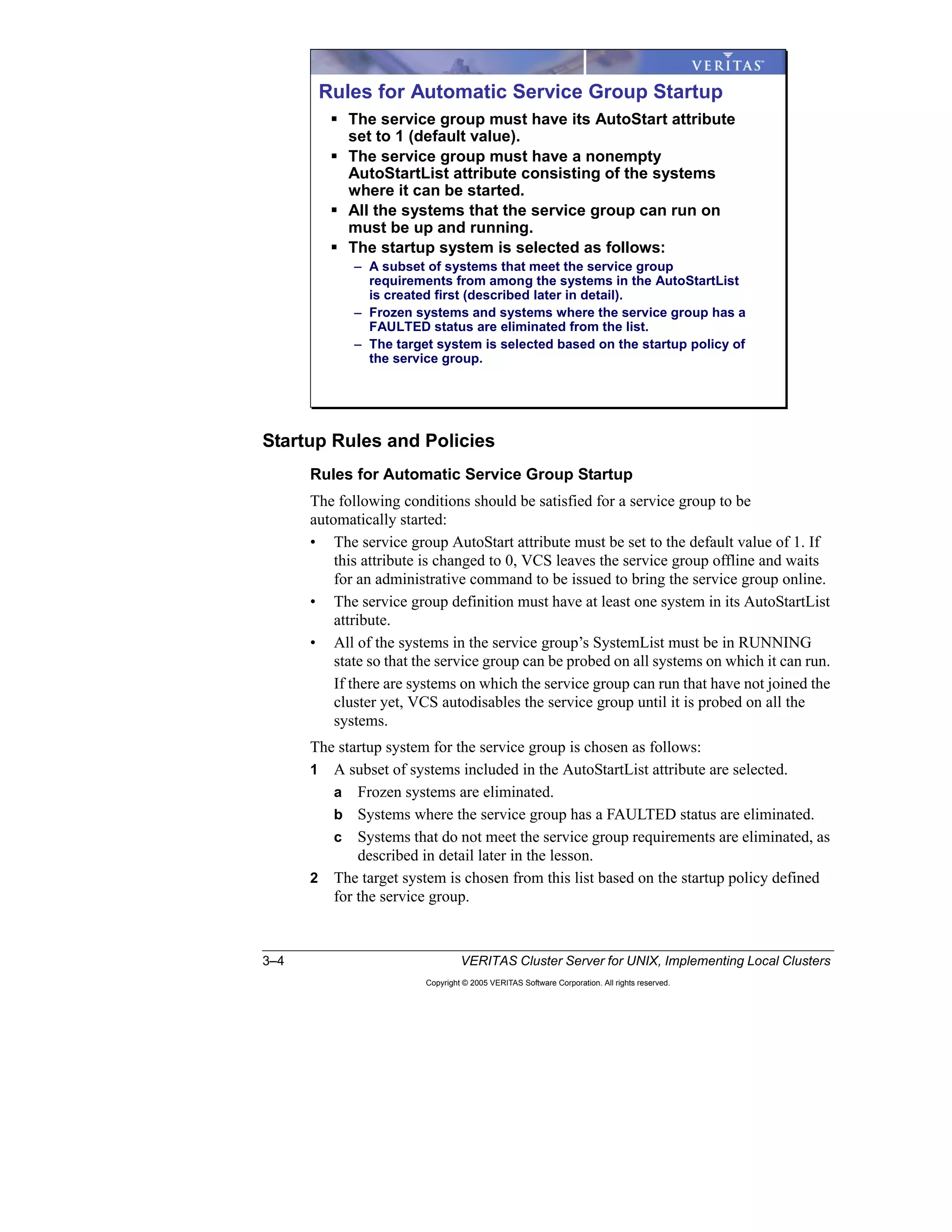
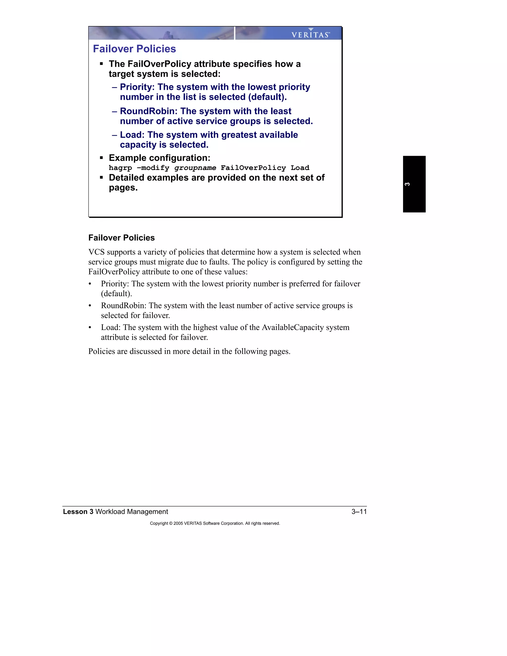
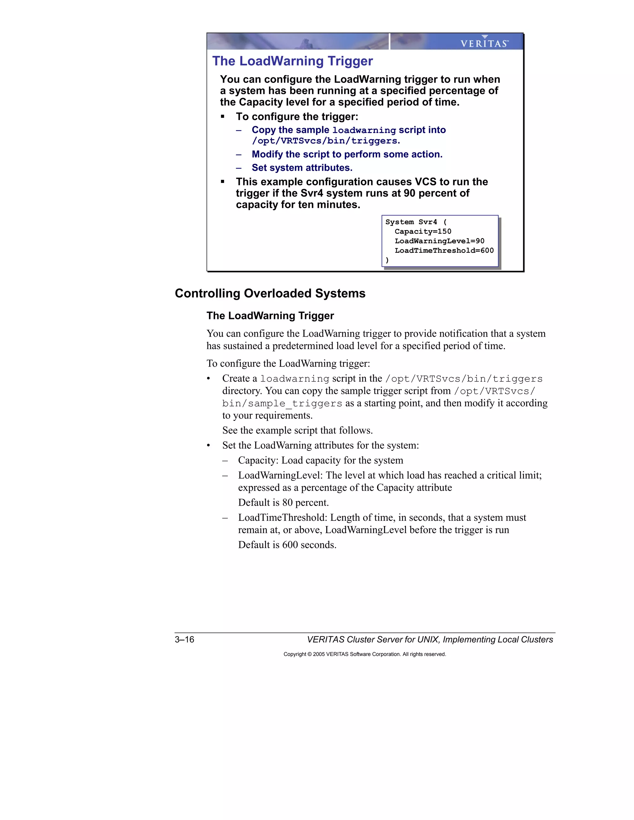
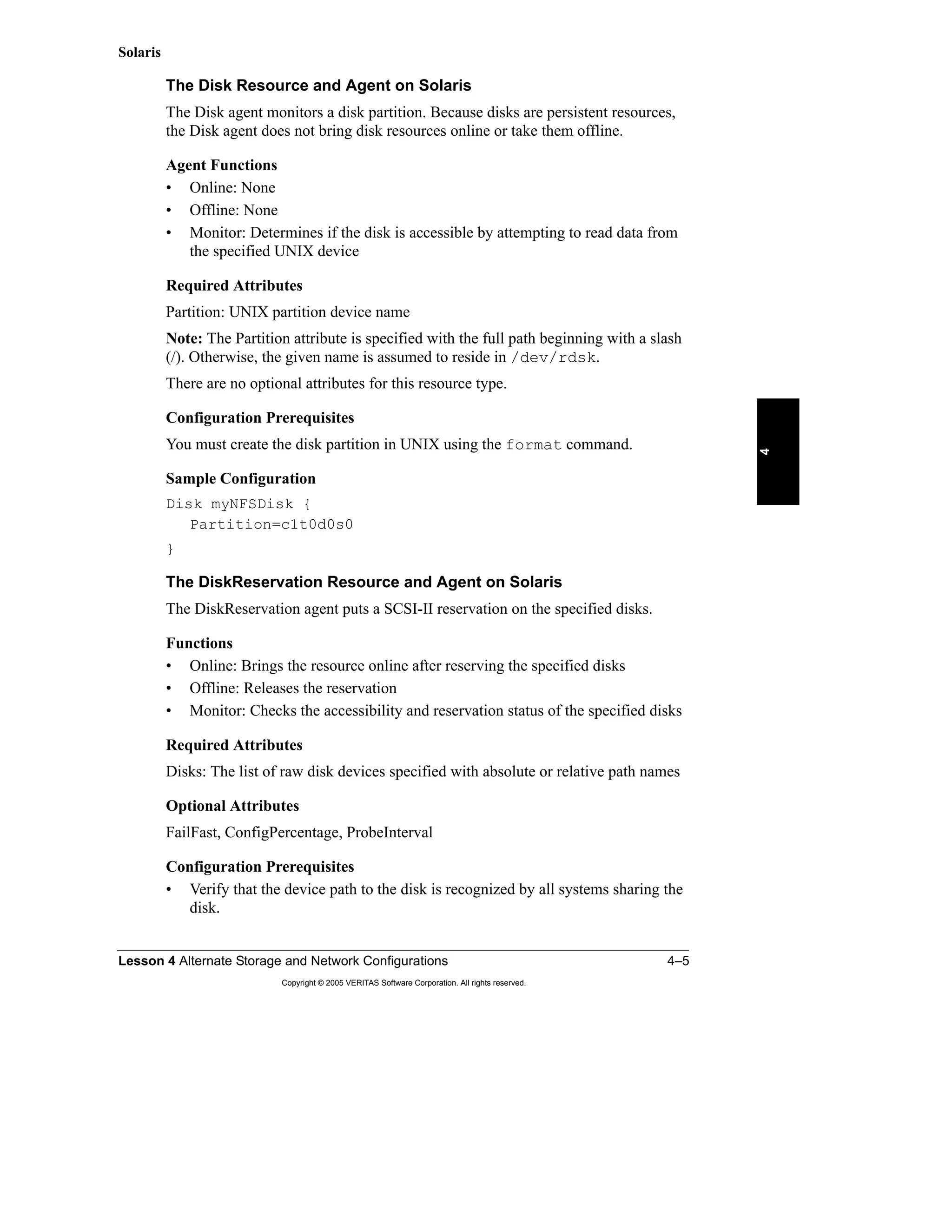
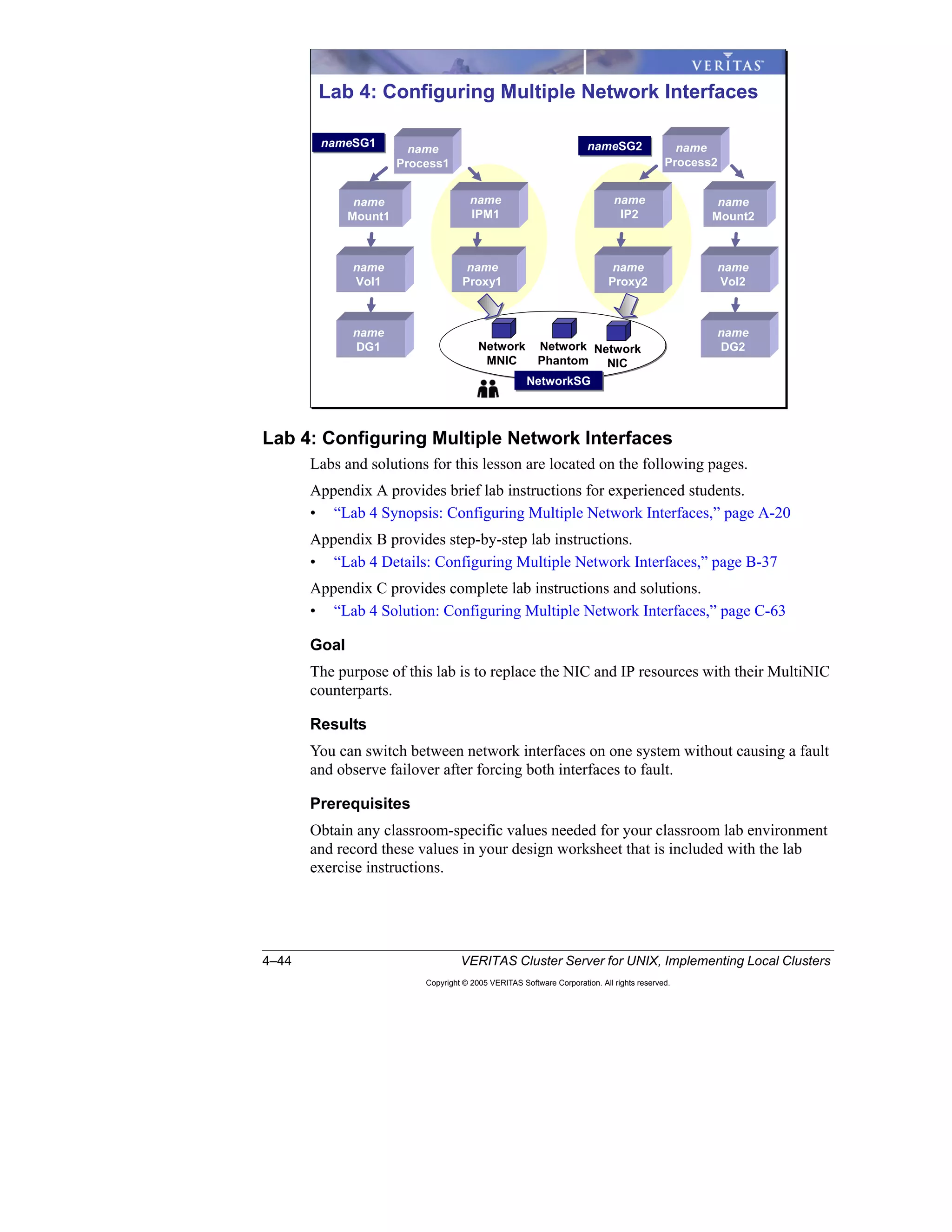
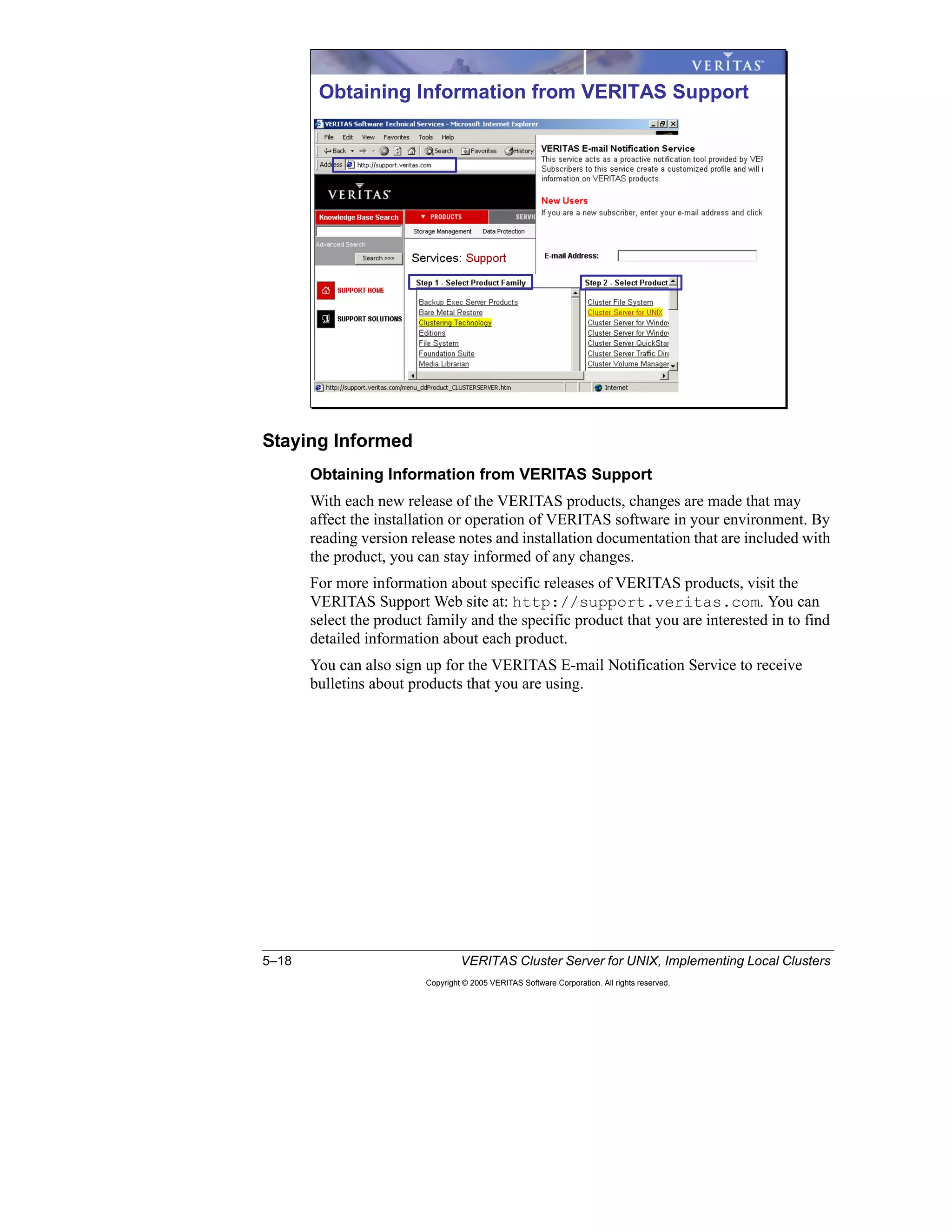
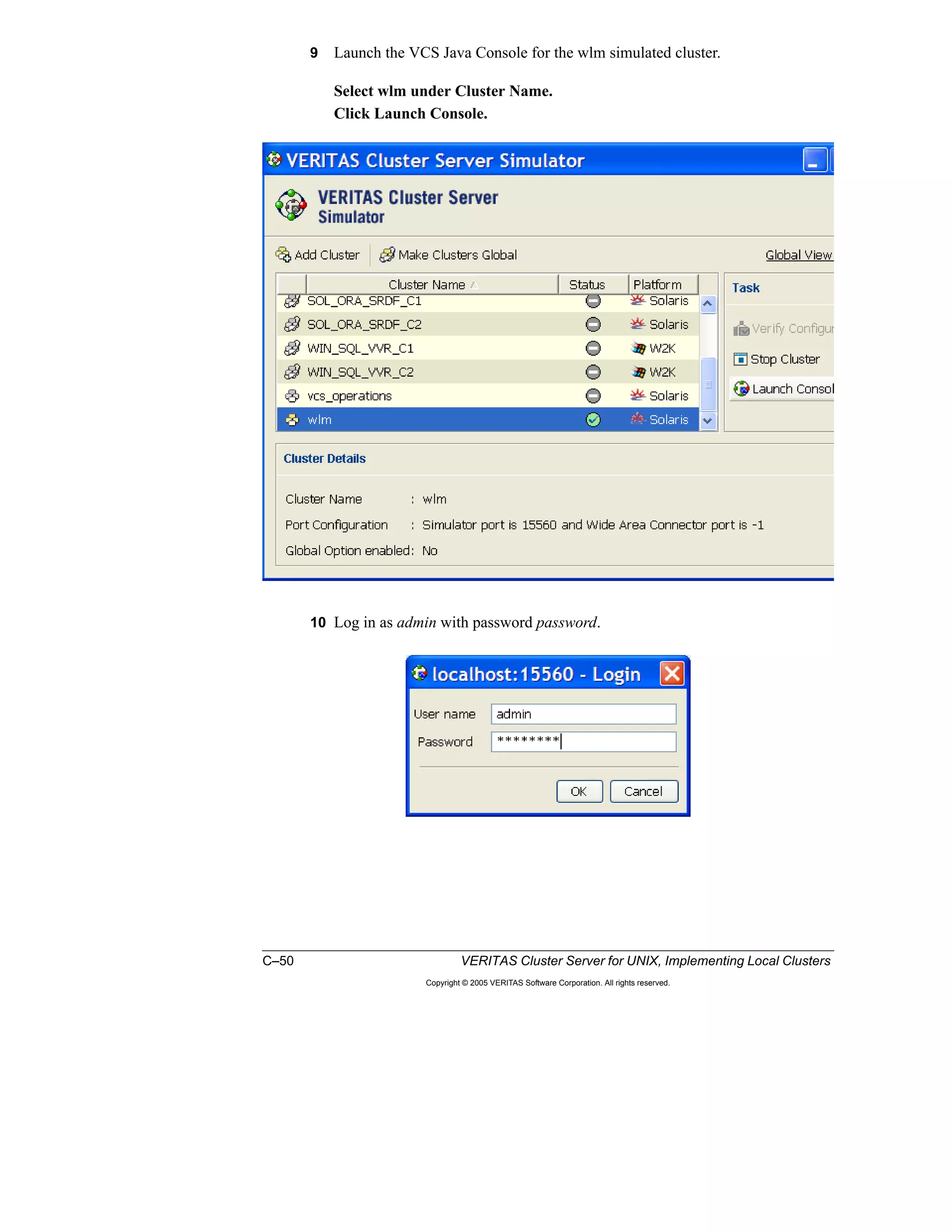
Example Script
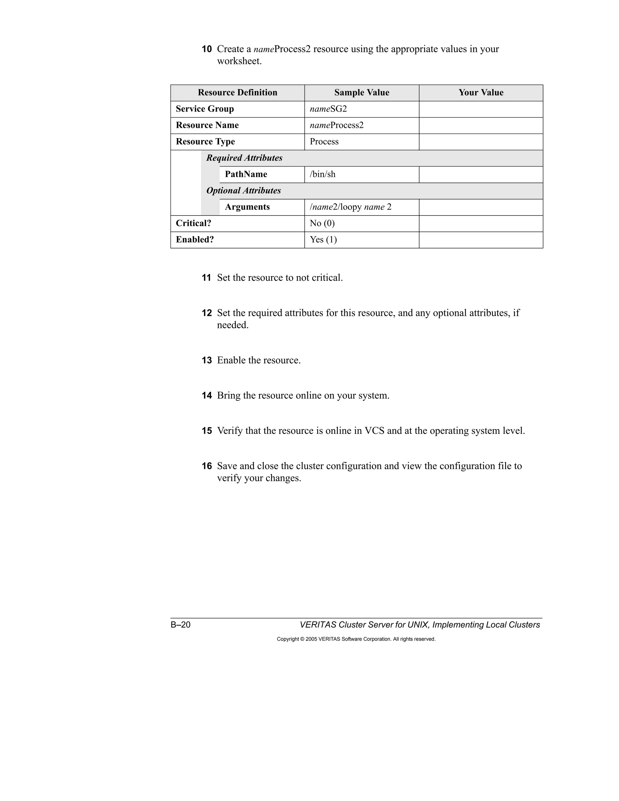
A portion of the sample script, /opt/VRTSvcs/bin/sample_triggers/
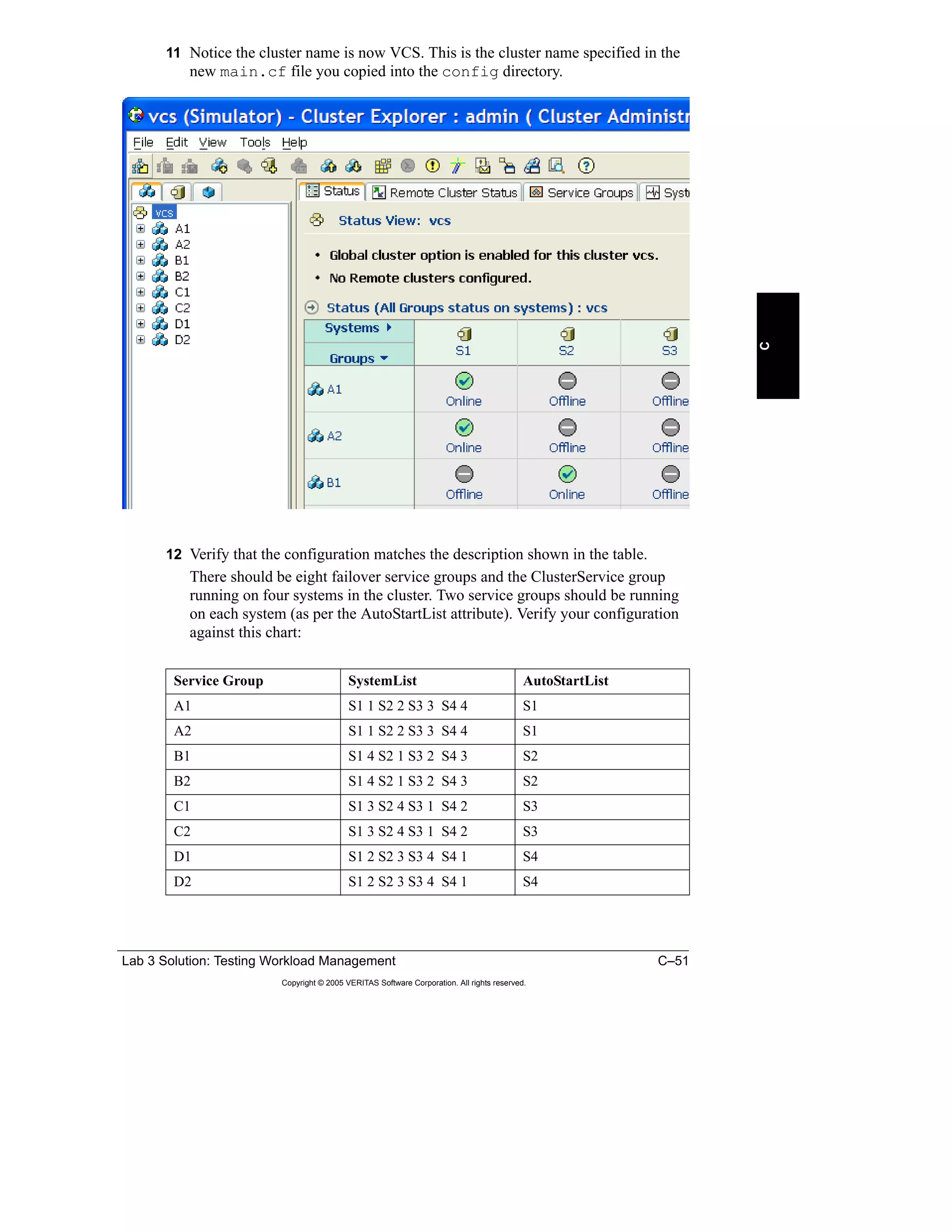
loadwarning, is shown to illustrate how you can provide a basic operator
warning. You can customize this script to perform other actions, such as switching
or shutting down service groups.
# @(#)/opt/VRTSvcs/bin/triggers/loadwarning
@recipients=("username@servername.com");
#
$msgfile="/tmp/loadwarning";
`echo system = $ARGV[0], available capacity = $ARGV[1] >
$msgfile`;
foreach $recipient (@recipients) {
## Must have elm setup to run this.
`elm -s loadwarning $recipient < $msgfile`;
}
`rm $msgfile`;
exit](https://image.slidesharecdn.com/ha-vcs-410-101a-2-10-srtpg4-130918134145-phpapp01/75/havcs-410-101-a-2-10-srt-pg_4-103-2048.jpg)


![4–32 VERITAS Cluster Server for UNIX, Implementing Local Clusters
Copyright © 2005 VERITAS Software Corporation. All rights reserved.
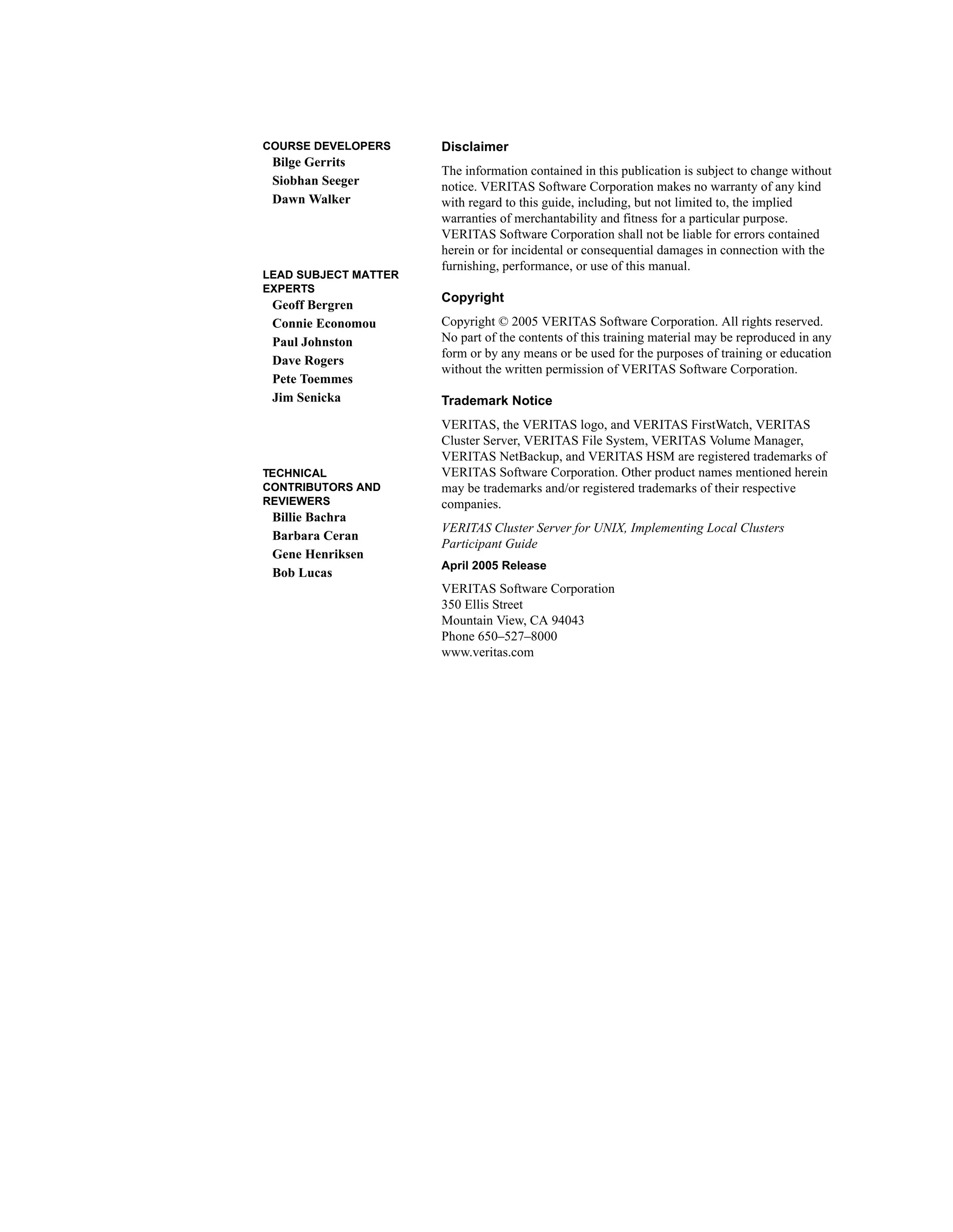
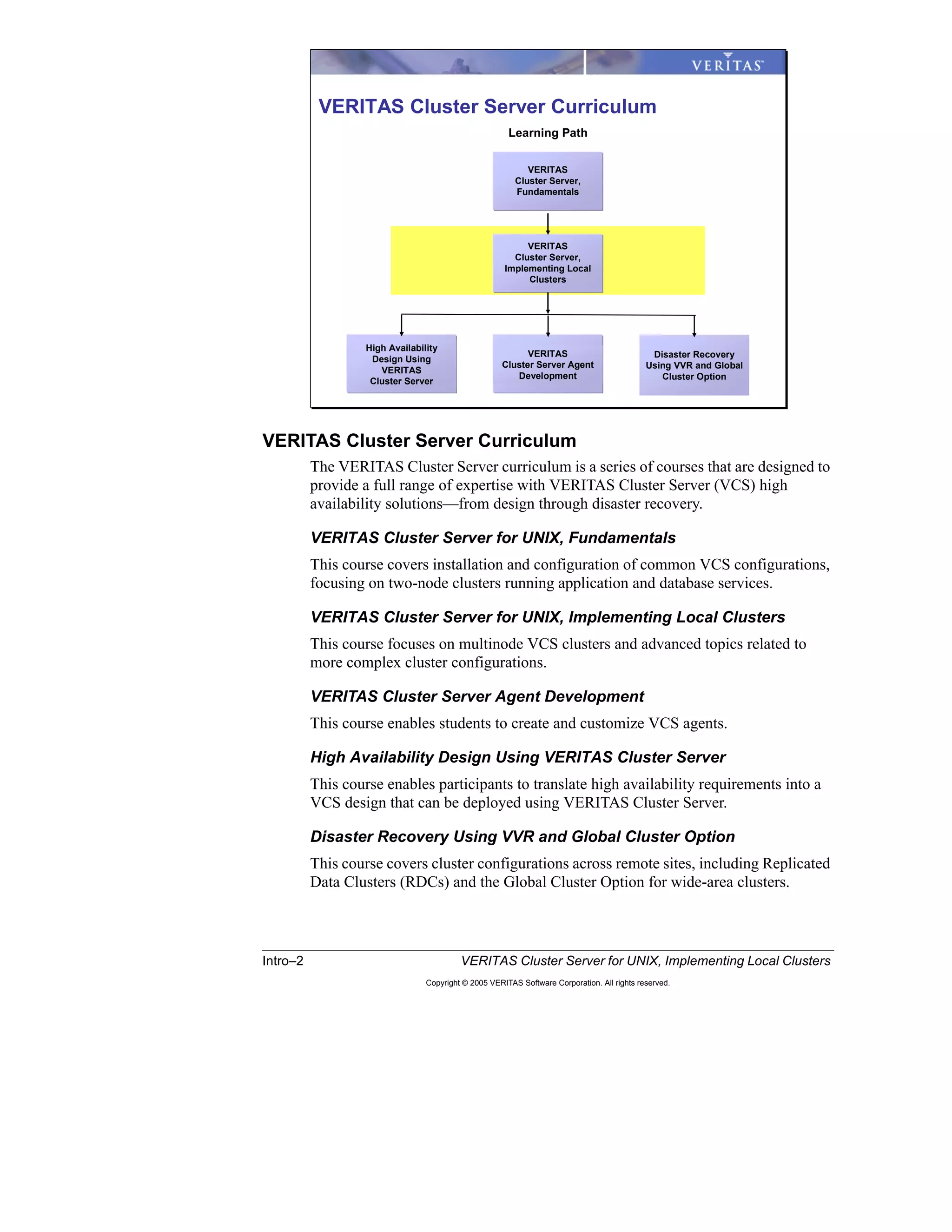
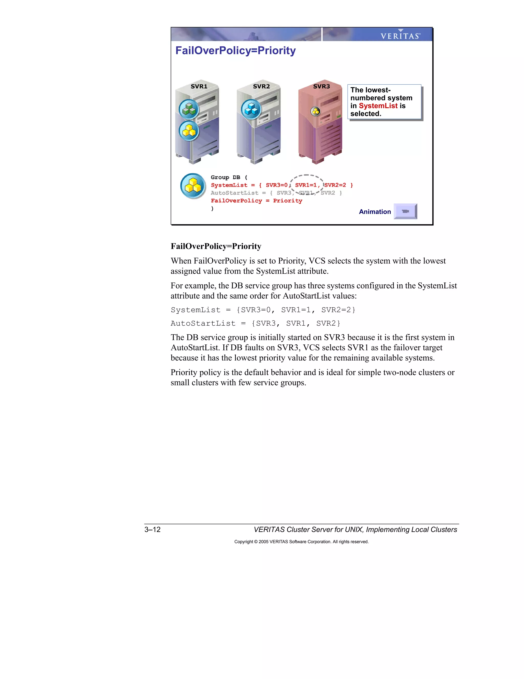
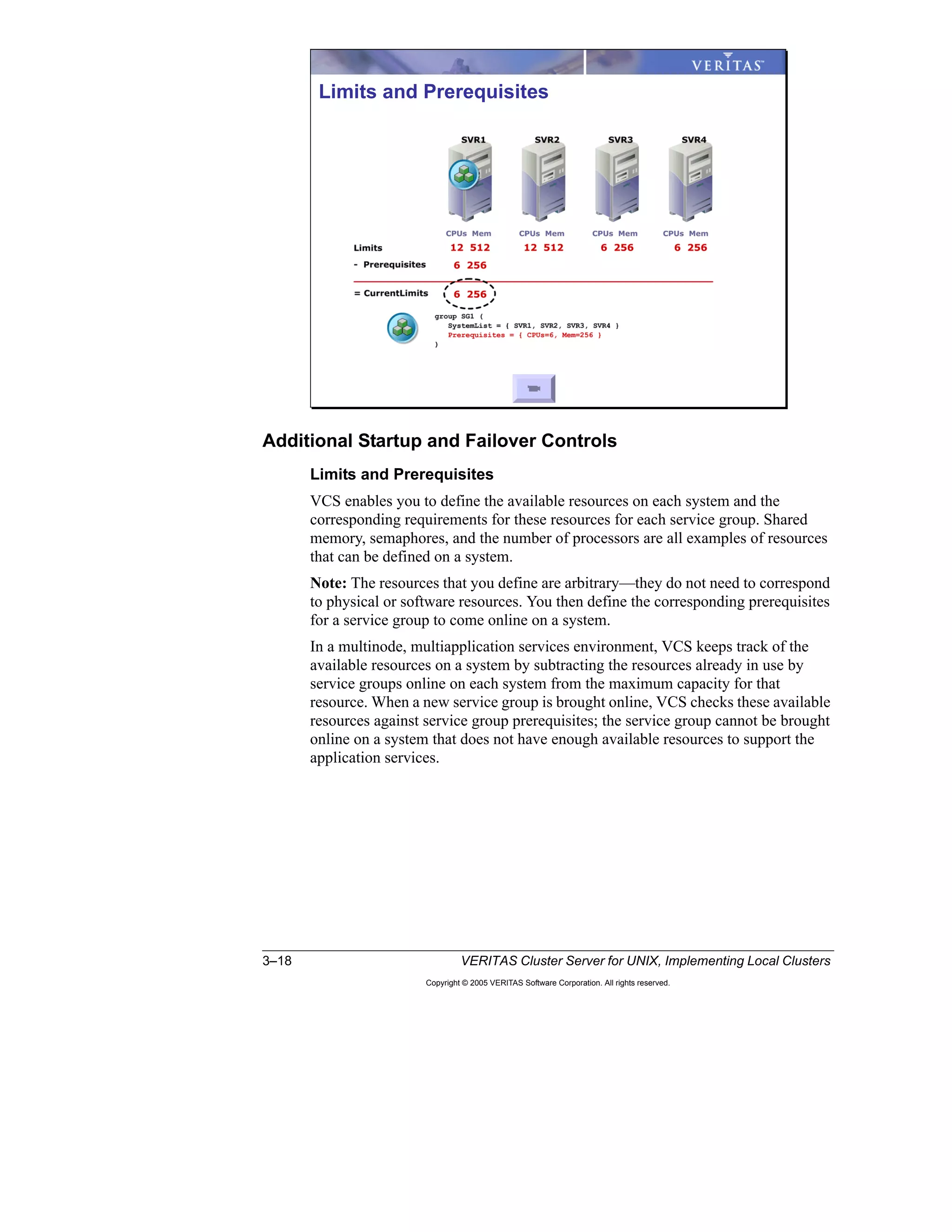
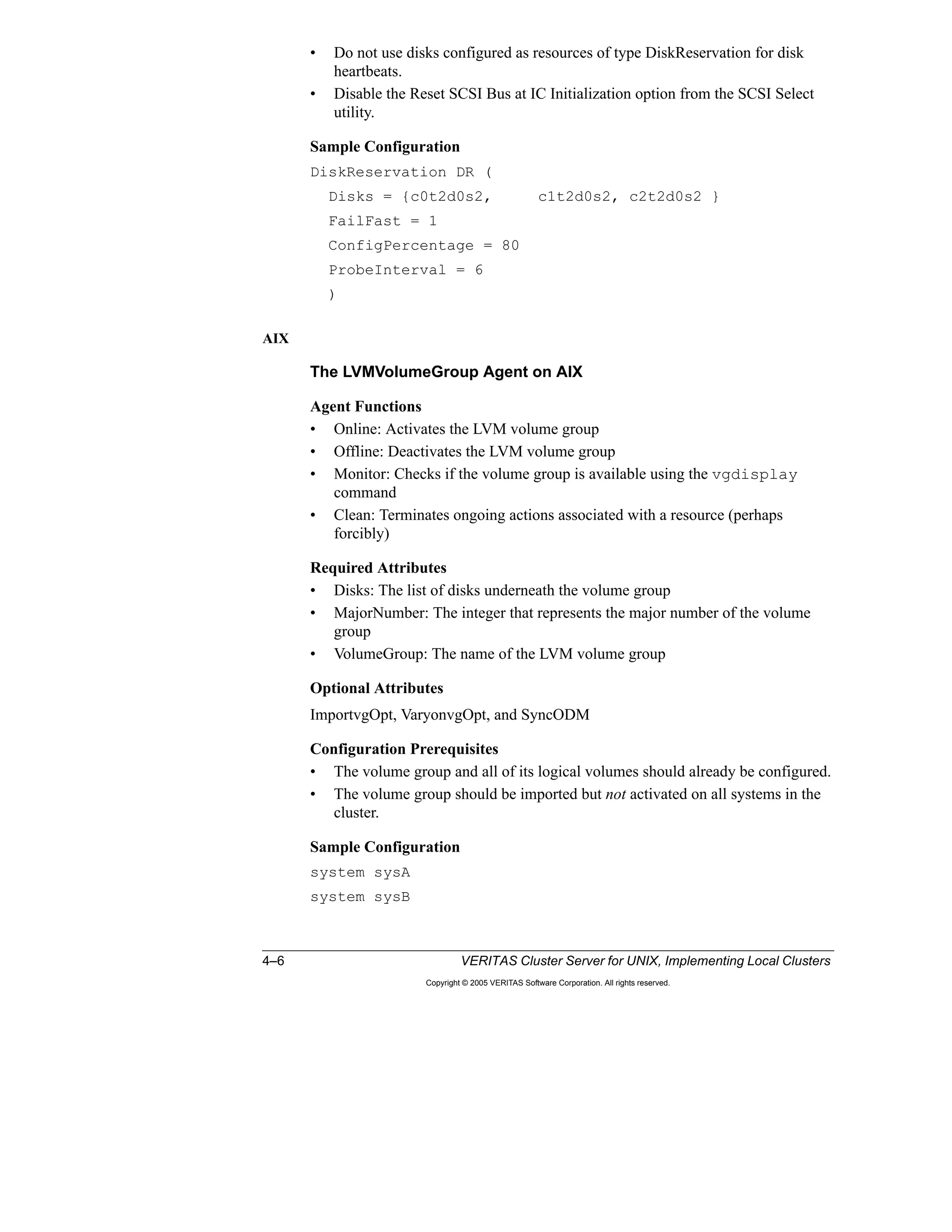
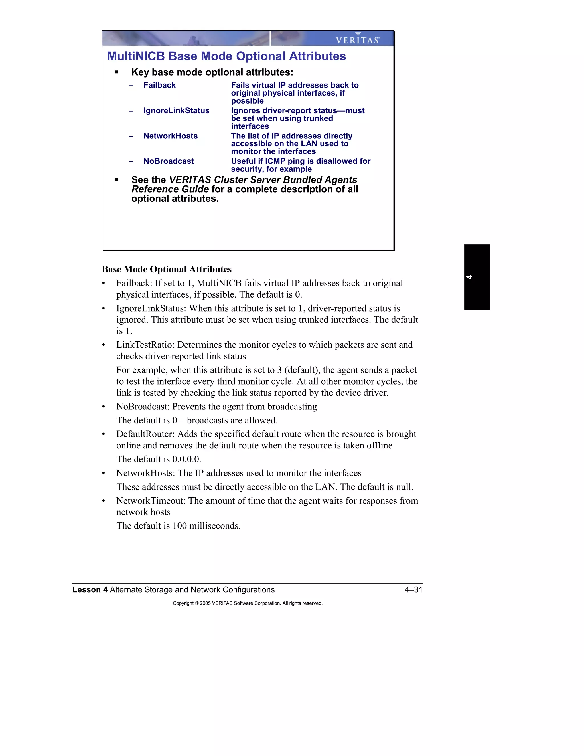
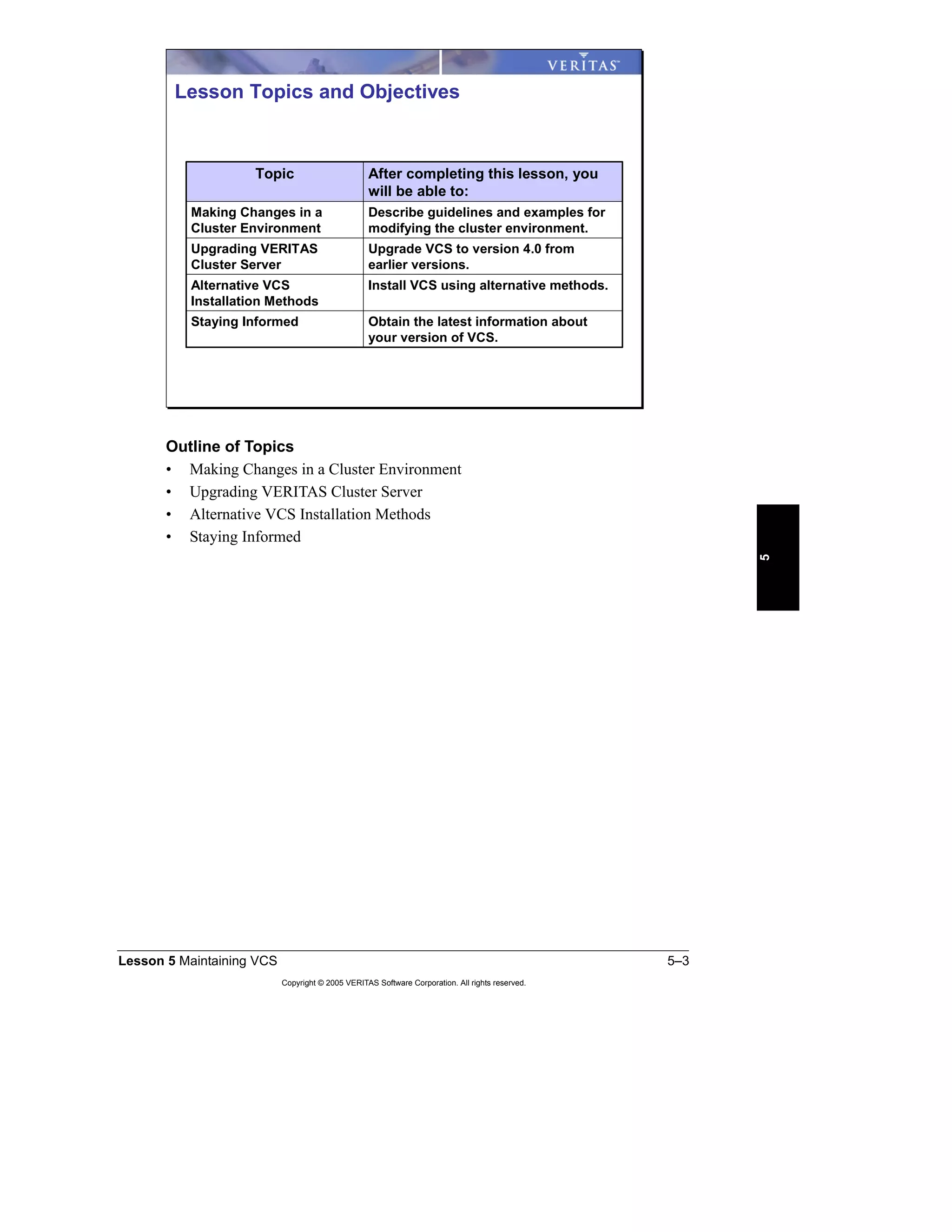
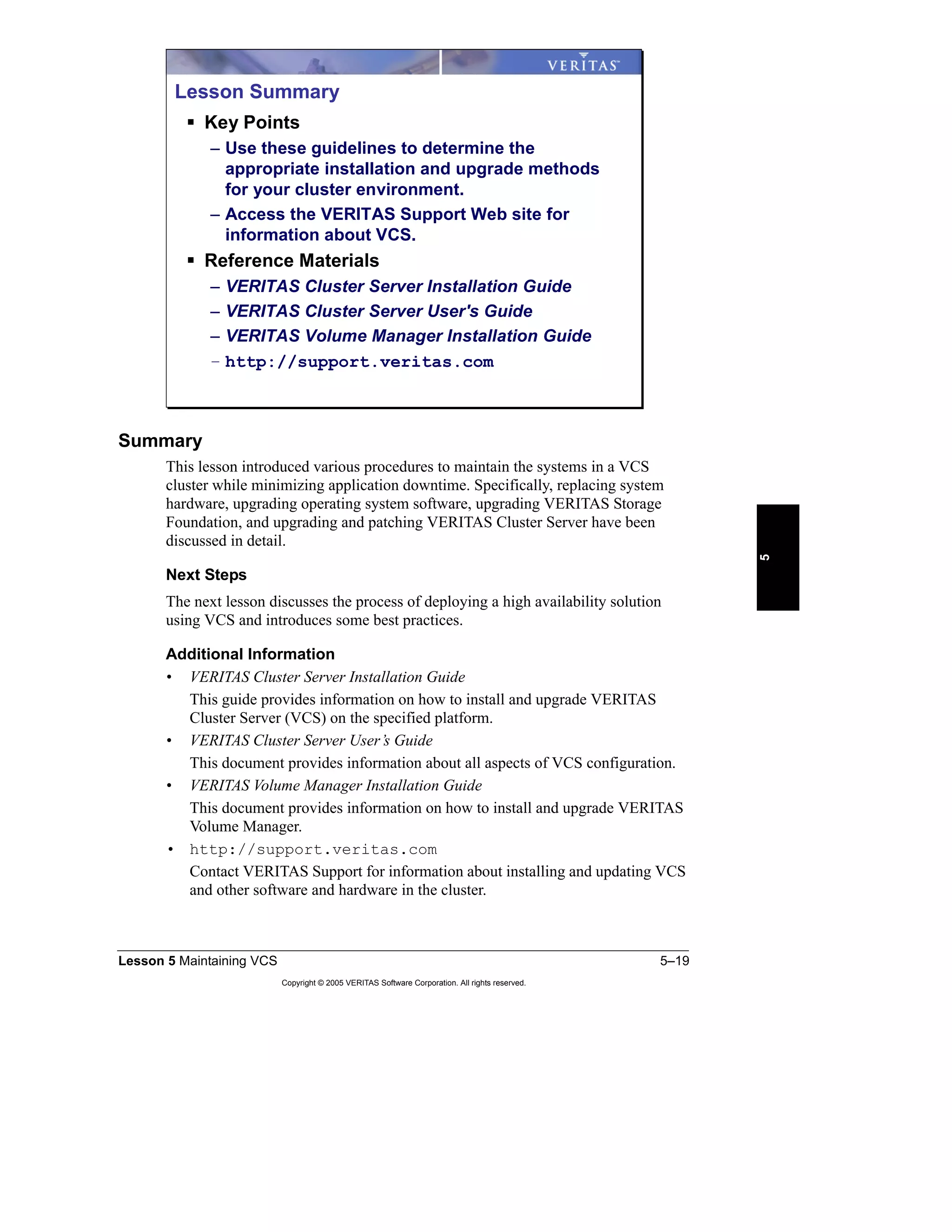
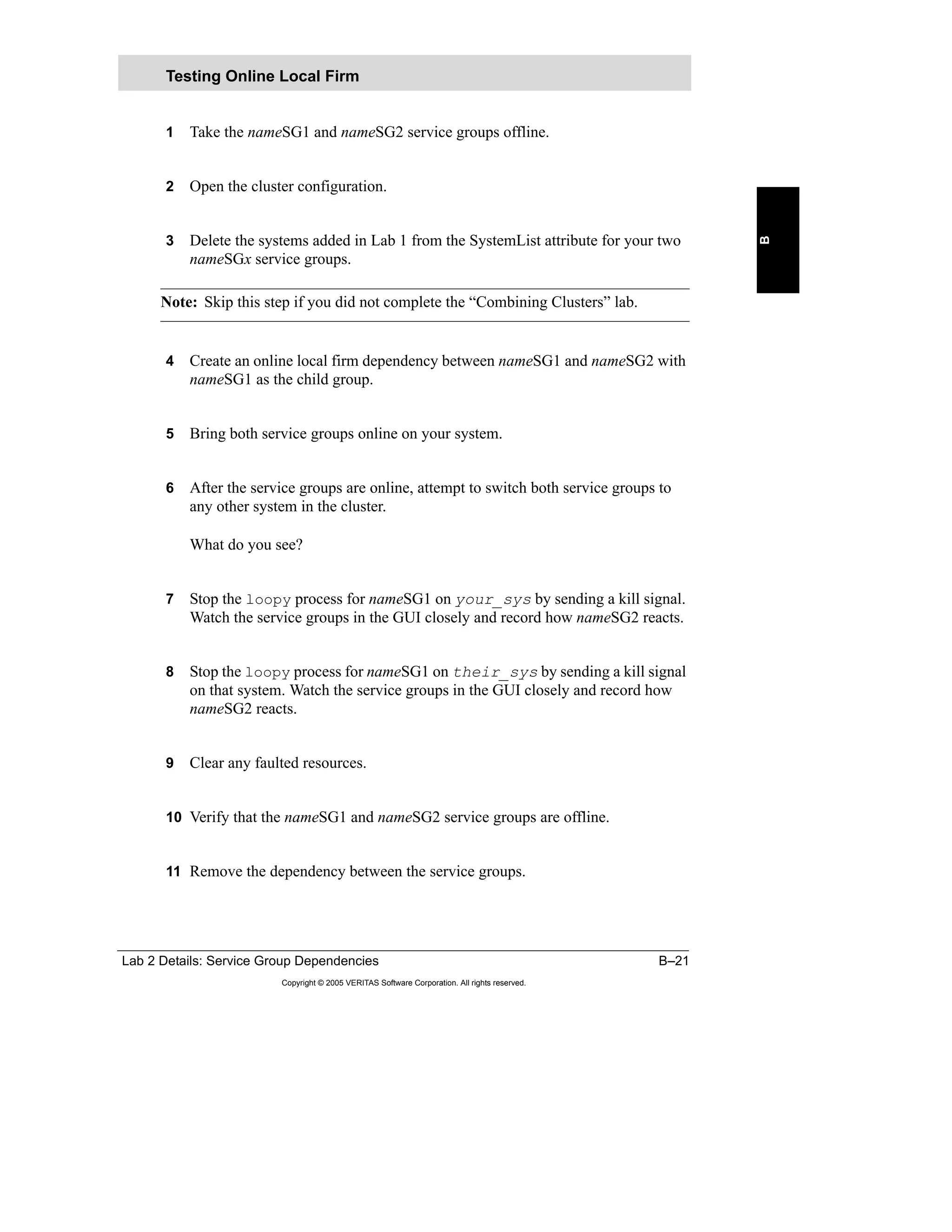
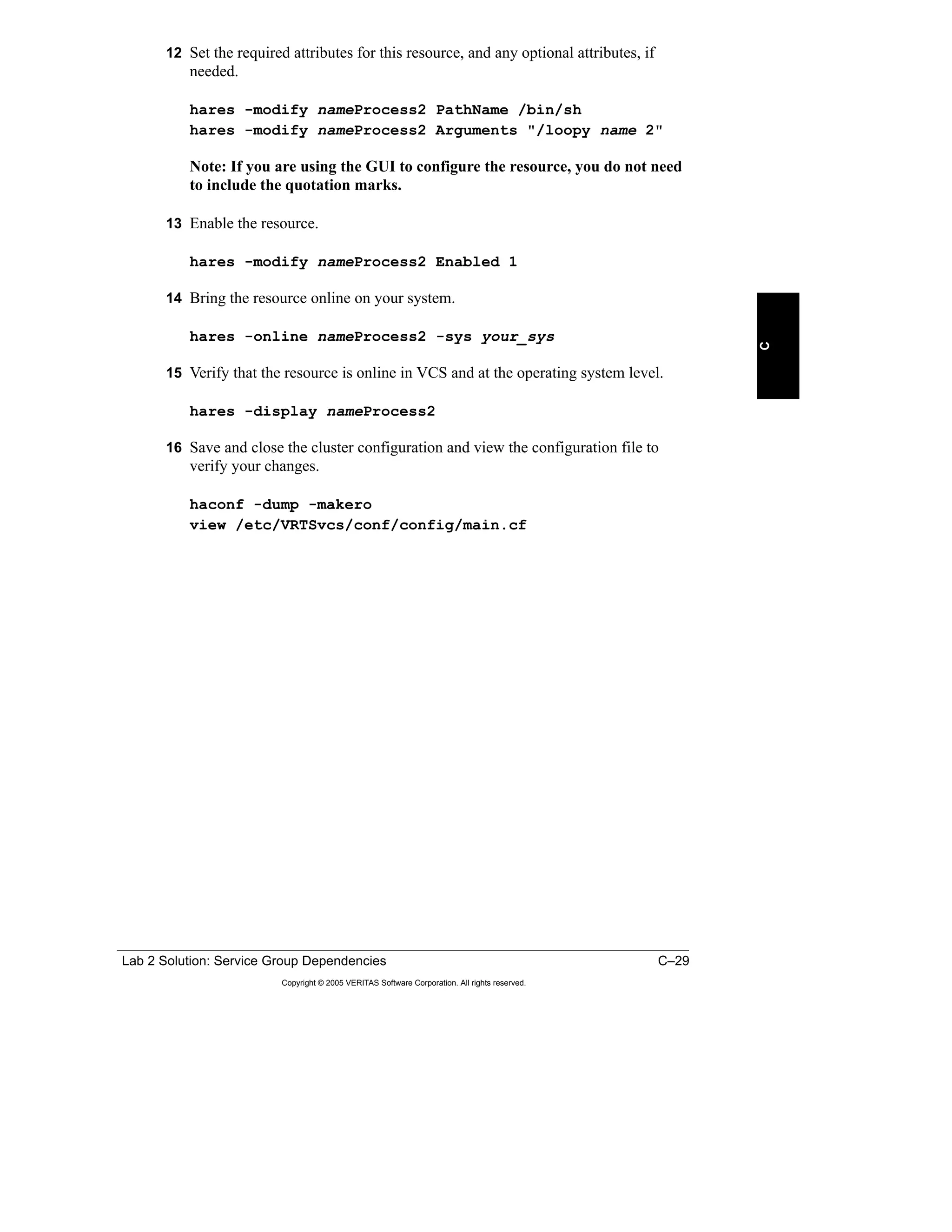
• OnlineTestRepeatCount, OfflineTestRepeatCount: The number of times an
interface is tested if the status changes
For every repetition of the test, the next system in NetworkHosts is selected in
a round-robin manner. A greater value prevents spurious changes, but it also
increases the response time.
The default is 3.
The resource type definition in the types.cf file displays the default values for
MultiNICB attributes:
type MultiNICB (
static int MonitorInterval = 10
static int OfflineMonitorInterval = 60
static int MonitorTimeout = 60
static int Operations = None
static str ArgList[] = { UseMpathd,MpathdCommand,
ConfigCheck,MpathdRestart,Device,NetworkHosts,
LinkTestRatio,IgnoreLinkStatus,NetworkTimeout,
OnlineTestRepeatCount,OfflineTestRepeatCount,
NoBroadcast,DefaultRouter,Failback }
int UseMpathd = 0
str MpathdCommand = "/sbin/in.mpathd"
int ConfigCheck = 1
int MpathdRestart = 1
str Device{}
str NetworkHosts[]
int LinkTestRatio = 1
int IgnoreLinkStatus = 1
int NetworkTimeout = 100
int OnlineTestRepeatCount = 3
int OfflineTestRepeatCount = 3
int NoBroadcast = 0
str DefaultRouter = "0.0.0.0"
int Failback = 0
)](https://image.slidesharecdn.com/ha-vcs-410-101a-2-10-srtpg4-130918134145-phpapp01/75/havcs-410-101-a-2-10-srt-pg_4-144-2048.jpg)


![Exchange 2010 on_v_mware_-_best_practices_guide[1]](https://cdn.slidesharecdn.com/ss_thumbnails/exchange2010onvmware-bestpracticesguide1-101229092935-phpapp02-thumbnail.jpg?width=640&height=640&fit=bounds)