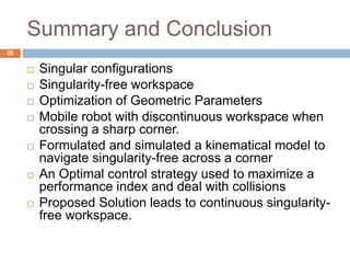
A mobile parallel robot used for pipeline inspection is analyzed. The robot consists of single modules resembling a snake. The study determines the robot's singularity-free workspace and derives optimal geometric parameters. When passing through sharp corners in the pipe, the robot encounters singular configurations that disrupt mobility. To overcome this, prismatic joints are added to the arms, allowing continuous singularity-free motion across corners through optimal control strategies like path following control and gradient ascent to maximize arm length. Simulation results demonstrate the robot can navigate corners without getting stuck, leading to a continuous singularity-free workspace.

![Snake-like Pipeline Inspection
Robot
Explorer 10/14 [Photograph]. Retrieved 11 December, 2013, from Pipetel technologies
Inc. http://www.pipetelone.com/explorer_10-14.html
2](https://image.slidesharecdn.com/35db5ad6-1d93-4fc7-acfe-0d1c364b8065-160404144025/85/Hassan-Thesis-Presentation-Dec16-2-320.jpg)

![Contribution
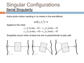
Analysis of a single module of a snake-like
pipeline inspection robot.
Study of Workspace and Singularities
Determination of Optimal Geometry
Optimal Control in a Geometrically Singular pipe
Explorer 10/14 [Photograph]. Retrieved 11 December, 2013, from Pipetel technologies
Inc. http://www.pipetelone.com/explorer_10-14.html
4](https://image.slidesharecdn.com/35db5ad6-1d93-4fc7-acfe-0d1c364b8065-160404144025/85/Hassan-Thesis-Presentation-Dec16-4-320.jpg)


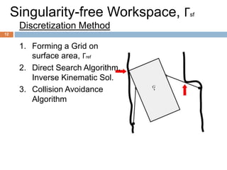


![Step 1:
Step 2:
]0[l ]0[w ]0[h ]0[a
0001 ,,,Fmax ahwll
ldl
]1[l
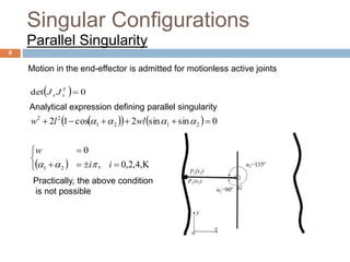
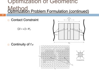
Optimization of Geometric
MethodOptimization Technique: Parametric Variation
32](https://image.slidesharecdn.com/35db5ad6-1d93-4fc7-acfe-0d1c364b8065-160404144025/85/Hassan-Thesis-Presentation-Dec16-32-320.jpg)
![Step 1:
Step 2:
]0[l ]0[w ]0[h ]0[a
0001 ,,,Fmax ahwlw
wdw
]1[l ]1[w
Optimization of Geometric
MethodOptimization Technique: Parametric Variation
33](https://image.slidesharecdn.com/35db5ad6-1d93-4fc7-acfe-0d1c364b8065-160404144025/85/Hassan-Thesis-Presentation-Dec16-33-320.jpg)
![Step 1:
Step 2:
]0[l ]0[w ]0[h ]0[a
ahwla
ada
,,,Fmax 0001
]1[l ]1[w ]1[h ]1[a
Optimization of Geometric
MethodOptimization Technique: Parametric Variation
34](https://image.slidesharecdn.com/35db5ad6-1d93-4fc7-acfe-0d1c364b8065-160404144025/85/Hassan-Thesis-Presentation-Dec16-34-320.jpg)
![Step 1:
Step 2:
Step 3: Repeat the above process
]0[l ]0[w ]0[h ]0[a
]1[l ]1[w ]1[h ]1[a
qq 1
][ql ][qw ][qh ][qa ][q
Optimization of Geometric
MethodOptimization Technique: Parametric Variation
35](https://image.slidesharecdn.com/35db5ad6-1d93-4fc7-acfe-0d1c364b8065-160404144025/85/Hassan-Thesis-Presentation-Dec16-35-320.jpg)