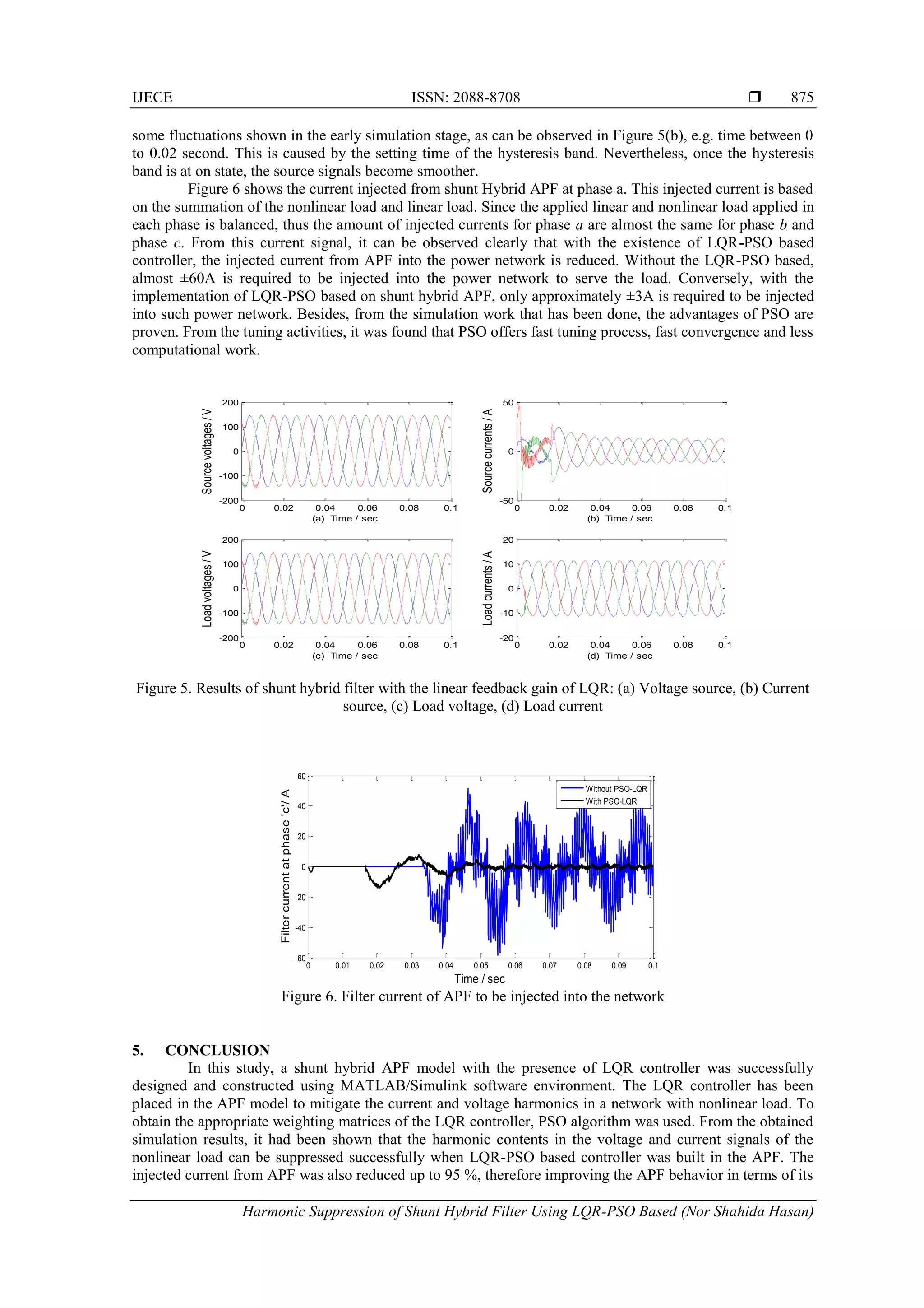
International Journal of Electrical and Computer Engineering (IJECE)
Vol. 7, No. 2, April 2017, pp. 869~876
ISSN: 2088-8708, DOI: 10.11591/ijece.v7i2.pp869-876  869
Journal homepage: http://iaesjournal.com/online/index.php/IJECE
Harmonic Suppression of Shunt Hybrid Filter using
LQR-PSO based
Nor Shahida Hasan1
, Norzanah Rosmin2
, Saifulnizam Abd Khalid3
, Dygku. Asmanissa Awg. Osman4
,
Baharuddin Ishak5
, Aede Hatib Mustaamal6
1,2,4
Centre of Electrical Energy System (CEES), POWER Department, Faculty of Electrical Engineering, Universiti
Teknologi Malaysia, 81310 Skudai, Johor, Malaysia.
3
POWER Department, Faculty of Electrical Engineering, Universiti Teknologi Malaysia, 81310 Skudai, Johor, Malaysia.
5
Tenaga Nasional Berhad (TNB), Protection Unit, Distribution Department, 80100 Jln Yahya Awal, Johor, Malaysia.
6
Faculty of Education, Universiti Teknologi Malaysia, 81310 Skudai, Johor, Malaysia
Article Info ABSTRACT
Article history:
Received Jan 10, 2017
Revised Mar 14, 2017
Accepted Mar 28, 2017
In linear quadratic regulator (LQR), two different weighting matrices play an
important role in presenting the performance of this controller. Instead of
using classic common approach, which is trial and error method, this study
proposes a particle swarm optimization (PSO) algorithm to track the best
solution of the weighting matrices. The proposed algorithm is tested on shunt
hybrid active power filter (APF) to mitigate the harmonic contents in voltage
and current signals in a nonlinear load system. The modeling work of this
proposed system is simulated using MATLAB/Simulink software. From the
simulation, the obtained results proved that using PSO in tuning the LQR
controller produce smoother nonlinear voltage and current signals. In fact,
the amount of current to be injected into network can be reduced up to 95%.
Besides, less time is consumed during searching the optimum weighting
matrices using the proposed approach.
Keyword:
Active power filter
Harmonic suppression
LQR controller
PSO tuning
Shunt hybrid APF
Copyright © 2017 Institute of Advanced Engineering and Science.
All rights reserved.
Corresponding Author:
Nor Shahida Hasan,
Centre of Electrical Energy System (CEES),
POWER Department,
Faculty of Electrical Engineering,
Universiti Teknologi Malaysia,
81310 Skudai, Johor, Malaysia.
Email: norzanah@utm.my
1. INTRODUCTION
The main issue regards to power quality is the power system harmonics. The rapid growth of
nonlinear loads and harmonics in current and voltage signals in the power network has become a great deal.
Several power quality issues, their causes and other possible solutions in handling these problems were
explained in details in [1]. The most conventional methods in dealing with these harmonics problems are
using L-C filter and capacitor bank [2], [3]. However, these passive filters have several drawbacks such as
fixed compensation, large size, high installation cost and resonance problem [4]. Thus, to overcome these
shortcomings, an active power filter (APF) is employed in this work. The ability of APF to inject current into
its system promises to provide durability and reliability in its performance.
Technically, APF is designed to produce certain amount of current to be injected into the electrical
network in order to drain out the harmonic components of current or voltage signals. The amount of injected
current is controlled based on error value between reference and measured current/voltage signals. Later on,
the error then converted into pulse width modulation to switch the inverter. In power electronic point of view,
this process is quite similar with the voltage/current source inverter [5]. Numbers of publications have proved
that shunt APF can successfully mitigate harmonic voltage/current and compensate the reactive power in
 ISSN: 2088-8708
IJECE Vol. 7, No. 2, April 2017 : 869 – 876
870
electrical system [6], [7]. Nonetheless, this APF has an adverse trait in its switching process. Its fast
switching technique during high currents in power network generates high frequency ripple, which can cause
electromagnetic interference in distribution system [5], [6]. In such condition, different types of control
algorithms are adopted into APF to improve its steady state and dynamic performance. Various attempts of
controllers for APF application has been reviewed and proposed in the previous works, such as p-q (the
instantaneous reactive-power) theory, dead-beat controller, adaptive controls, Neuro, Fuzzy, wavelet control,
sliding mode control, and etc [4]. However, response time of such controllers are limited by microcontroller
speed and its performance becomes worst when dealing with nonlinear loads [8]. LQR is a controller that
offers optimal tuning of the multivariable feedback gain. LQR is well known of its behavior of robust,
efficient and suitable for multi input and multi output [MIMO] systems [9], [10]. Thus a LQR is chosen in
this study to mitigate the harmonic voltage and current in shunt hybrid APF.
Theoretically, LQR minimizes quadratic cost function, J that consists of state weighting matrices, Q
and control weighting matrices. These two parameters greatly influence the performance of LQR controller.
It can be determined using Riccati Equation [11]. Nevertheless, most common approach in obtaining these
two parameters is using trial and error method [3], [6]. This classic approach is labor-extensive, time
consuming and do not promise the expected performance. Thus, the authors in [12] gave brief explanation on
existing optimization techniques to be implemented with LQR, for example, artificial bee colony (ABC),
artificial immune systems (AIS), ant colony optimization (ACO), genetic algorithm (GA), artificial neural
networks (ANN) and more. However extensive procedure and extra parameters is required to employ these
optimization techniques. Therefore, for the sake of simplicity, PSO is proposed in this work to tune the LQR
controller in mitigating harmonic voltage and current at nonlinear load.
In comparison with other optimization techniques, PSO promises robust in action, high efficiency,
better results, cheaper and less time consuming in tracking the best solution of the fitness [12]. In fact, one of
the most attractive feature of PSO is its final solution do not rely on the initial states of the particles. Thus, it
makes the coding process in m.file easier [13]. LQR-PSO based had been applied on air craft landing [14],
controlling the rotating inverse pendulum [15], stabilizing a two-wheeled wheelchair in balancing mode [16],
controlling liquid level in the tank [17] and etc. However, LQR-PSO based implementation on three phase
shunt hybrid filter, is somewhat missing in this literature, thus it leads to the main focused of this work.
2. DESCRIPTION OF THE PROPOSED SYSTEM
The shunt hybrid model of APF in suppressing harmonic content in electrical system is illustrated in
Figure 1. This model comprises of three phase voltage sources, APF, capacitor bank and loads (linear and
nonlinear). The phase voltage ( ) is set as 176.7 Vrms, with resistance (Rs) and inductance (Ls) value of
0.0015 Ω and 0.1 mH, respectively. The value of the capacitor (Cf) for the capacitor bank is set to be 99.3µF
per phase. In this hybrid model, the APF performs the harmonic current mitigation, while the capacitor bank
acts as a reactive power compensator besides providing the path to drain the harmonic ripple. The parameter
values and the basic structure of this model is based on work in [6], but in this work, some modification in
terms of tuning the two weighting matrices using PSO is performed.
Figure 1. Full system model of shunt hybrid APF
2.1. Active power filter (APF)
The APF is constructed using 3-level voltage source inverter (VSI), capacitors (c1 = c2 = 500 μF)
and RL filter (Rf = 0.1Ω, Lf = 2 mH). The VSI regenerates the amount of current to be injected into the
network. The capacitors of c1 and c2 act as energy storage, where they inject certain amount of current into
the system every time they detect the error between reference and measured values. This error is then
su
APF
Supply Linear and
Nonlinear Load
Capacitor
bank
IJECE ISSN: 2088-8708 
Harmonic Suppression of Shunt Hybrid Filter Using LQR-PSO Based (Nor Shahida Hasan)
871
converted into pulse width modulation (PWM) signal to switch the IGBT/Diodes. The MATLAB view of the
APF model is displayed in Figure 2.
Figure 2. APF model
The reference current of APF is expressed in Equations (1) to (3) [6].
(1)
(2)
(3)
where , is the reference value of filter current for phase k, is the line current of phase k (measured at
B_Load block in Figure 1) and subscripts k denotes as phase a, b or c, respectively. is the power
submitted to load, is the sum of peak value of source voltage, is the power loss caused by capacitor
voltage variation (controlled via a PI controller), is the phase angle of the fundamental component of
load voltage at phase a and is the angular speed at frequency of 60 Hz [6].
2.2. Shunt capacitor bank
In this shunt hybrid APF, the capacitor bank (CB) acts as a passive power filter, in which helps to
provide the draining path of the harmonic currents. The feature advantages of CB are low in cost and
flexibility in its installation [18].
2.3. Nonlinear load
Nonlinear load system that shown in Figure 1 is composed with linear and nonlinear loads. The
nonlinear load is 6-pulse diode rectifier while the linear load is a 3-phase series resistance-inductance branch
per phase (R = 15.4 Ω and L = 15.4 mH). The linear load is shunt connected to nonlinear load.
3. LQR CONTROLLER: PSO TUNING BASED
In this study, the performance index of LQR is tuned using PSO. PSO is chosen due to its simplicity
whereby only certain parameters are needed in writing the optimization code. Thus, enable faster tracking
process in searching the best value of corresponding dimensions.
3.1. Linear quadratic regulator (LQR)
Based on state equation of and , the equivalent state space equation,
and the state vector x for Figure 1 is presented as written in Equation (4) and Equation (5) accordingly [6].
)(sin
)(2
)()( 1
*
a
T
lossT
lafa t
U
PP
titi  


)3
2(sin
)(2
)()( 1
*  

 a
T
lossT
lbfb t
U
PP
titi
)3
2(sin
)(2
)()( 1
*  

 a
T
lossT
lcfc t
U
PP
titi
*
fki lki
TP
tU lossP
1a

uBxAx 

uDxCy 
x
 ISSN: 2088-8708
IJECE Vol. 7, No. 2, April 2017 : 869 – 876
872
(4)
(5)
where is the rated value of DC voltage, is the filter current, li is the load current, and is the
current and voltage of capacitor bank, respectively. and is the equivalent resistance and equivalent
inductance for linear and nonlinear load. is the linear state-feedback law, ( ) to minimize the
quadratic cost function, as written in Equation (6) [6]. K is the gain matrix, which can be obtained from
Riccati Equation [11].
(6)
where and are the semi-definite and a positive real symmetric weight matrix of state matrix x(t) and
input matrix u(t). The important matter in LQR control is obtaining the value of Qs and R weighting
matrices. It becomes more difficult when the system has more parameters and more input and output
variables. Thus, to overcome these restraints and reducing time-consuming approach, a PSO is adopted into
the system to tune the value of Q and R weighting matrices in an easier and faster way.x
3.2. Particle swarm optimization (PSO)
PSO algorithm is developed based on the nature behavior of swarm, fish flocking, bees, whales or
other animals while they are looking for their food [19]. Technically, the involved particles will fly around
with the updated velocity (Equation (7)) towards a new position (Equation (8)). They will keep on
competitively flying until they find the best value for the fitness function [20].
(7)
(8)
In this work, the fitness value is the integrated absolute error (IAE) between the references value of
state vector and its measured state vector . Since the state vector consists of filter current, voltage and
capacitor current, thus, all the obtained errors between these values will be summed up and stored in the
workspace as IAE. The reference value for filter current was given in section 2.1. While the reference value
for current, and voltage, of capacitor bank is obtained from positive sequence extraction of current
and voltage source [13]. On the other hand, the 4x4 diagonal matrixes of Q and 1x1 matrix of R will be set as
the dimension. Therefore, the dimension is set to 5 in the Matlab coding. Dimension can be defined as the
parameters to be optimized. The pseudo code for the PSO-based LQR is as follows [13]:
Initialize each particle.
Do
Find R, Q,P (using Reccati Equation) and K using xm K
Calculate )(tx
Call the simulink file
Calculate the IAE
Find bestp , if the present IAE(t) < IAE ( bestp ) then )(tx is the current bestp
mL
V
u
Ls
x
CCC
LL
R
LL
R
LL
R
x f
dc
s
fff
eqeq
eq
ff
f
ss
s




























































0
0
0
0
0
0
1
0
111
1
00
1
00
1
00
 T
clcf uiiix
dcV fi ci cu
eqR eqL
m xm K
J
tduRuxQxJ TT
)(
2
1
0
 

Q R
         111 2211  txgwctxpwctvtv ibestibestii
     tvtxtx iii  1
x
*
,kci *
,kcv
IJECE ISSN: 2088-8708 
Harmonic Suppression of Shunt Hybrid Filter Using LQR-PSO Based (Nor Shahida Hasan)
873
Set the current value as the new bestp
End
Choose the particle with the least IAE value of all the particles as the .
For each Particle:
Calculate particles velocity, update particles position and get Q and R.
End
Until all stopping criteria is met .
The parameters used during initialization and the whole processes are listed in Table 1 below. The
upper and lower level value is obtained from publication in [6].
Table 1. Parameters value for PSO
Parameters Value
Number of particles 20
Number of iterations 10
Number of dimension 5
0.4, 0.9, 1.5, 1.5
Upper band [30, 30, 30, 0, 0.1]
Lower band [0.0001, 0.0001, 0.0001, 0.0001, 0.0001]
After 10 iterations with 20 particles involved, the weighting matrices of Q and R, and feedback gain
matrix for each phase, , are obtained. The results for the gains of are given as written in Equation (9)
to Equation (11).
Q = diag ([5.7267 7.5435 21.6203 0.0001]) (9)
R = 0.0625 (10)
= [9.5373 5.1246 20.9674]
= [9.5373 5.1247 20.9625] (11)
= [9.5373 5.1247 20.9625]
These Qs, R and Ks are affected by the value of and . Since the involved nonlinear and
linear loads are in balanced condition, thus, the obtained linear feedback gain, is almost similar for each
phase. These values will keep on changing every time the simulation is run due to the existing code of
‘rand()’ in parameter Q and R. However, this value will not give much effect on the simulation results as
long as the simulation is run between the determined upper and lower band of PSO.
3.3. Pulse width modulation (PWM) analysis
Since the feedback gain, K value is measured for each phase, thus, in order to generate a switching
signal for phase a, all the measured IAE of the filter current, capacitor bank current and capacitor bank
voltage are summed up before entering the hysteresis band. Later on, these signals will be converted into
gating signal to switch the three levels IGBT/Diodes. The MATLAB view of these steps is shown in
Figure 3. For the switching signal generation for phase b and c, same step/process is applied.
bestg
2121 ,,, ccww
kK K
aK
bK
cK
eqR eqL
kK
 ISSN: 2088-8708
IJECE Vol. 7, No. 2, April 2017 : 869 – 876
874
Figure 3. Switching signals of IGBT/Diodes
4. RESULTS AND DISCUSSION
Figure 4 shows the source voltage, source current, load voltage and load current signals when the
shunt Hybrid APF system is self-controlled. Meanwhile, Figure 5 shows the same signals but with the
existence of LQR-PSO based control in the proposed APF system. From Figure 4(a) and Figure 4(b), it can
be observed that, without the implementation of LQR based PSO, the current and voltage signals at the
source side are influenced by the harmonic factor. Similar situation can be depicted to the generated voltage
and current signals at the load side, as depicted in Figure 4(c) and Figure 4(d), respectively. This is because,
at 0.04 sec, APF starts to inject the filter current into the network. However, due to the fast switching
behavior of APF [5], high frequency ripple is generated at voltage and current signals on both sides. Thus,
this proved that in the absence of an appropriate controller, the APF could increase the harmonic contents in
the current and voltage signals.
Meanwhile, as can be seen in Figure 5(a-d), the generated signals for source voltage, source current,
load voltage and load current are smoother and free from high frequency ripple compared to the signals in
Figure 4(a-d). The obtained voltage signal at load side (as shown in Figure 5(c)) is 150V, which is equaled to
the voltage at supply side (as shown in Figure 5(a)). This is because the balanced non linear load is
connected in parallel with supply. While, the current values on the supply side remains constant at 12A once
the hysteresis controller is switched on. On the contrary, load current remains constant at approximately 11A
throughout the simulation times. The reduction of current values from supply side (12A) to the load side
(11A) is due to the power losses in the system network during power transmission.
Figure 4. Results of shunt hybrid filter without the linear feedback gain of LQR: (a) Voltage source, (b)
Current source, (c) Load voltage, (d) Load current
Obviously, with the presence of LQR-PSO based controller, with the tuned value of feedback gain,
K, the harmonic content in both source and load sides are suppressed, as shown in Figure 5(a) to
Figure 5(d). Thus, with the existence of tuned K parameter in the LQR-PSO based controller, smoother
voltage and current signals can be supplied to the load side. However, as can be seen in this figure, there are
0 0.02 0.04 0.06 0.08 0.1
-500
0
500
(a) Time / sec
Sourcevoltages/V
0 0.02 0.04 0.06 0.08 0.1
-500
0
500
(b) Time / sec
Sourcecurrents/A
0 0.02 0.04 0.06 0.08 0.1
-500
0
500
(c) Time / sec
Loadvoltages/V
0 0.02 0.04 0.06 0.08 0.1
-20
-10
0
10
20
(d) Time / sec
Loadcurrents/A
IJECE ISSN: 2088-8708 
Harmonic Suppression of Shunt Hybrid Filter Using LQR-PSO Based (Nor Shahida Hasan)
875
some fluctuations shown in the early simulation stage, as can be observed in Figure 5(b), e.g. time between 0
to 0.02 second. This is caused by the setting time of the hysteresis band. Nevertheless, once the hysteresis
band is at on state, the source signals become smoother.
Figure 6 shows the current injected from shunt Hybrid APF at phase a. This injected current is based
on the summation of the nonlinear load and linear load. Since the applied linear and nonlinear load applied in
each phase is balanced, thus the amount of injected currents for phase a are almost the same for phase b and
phase c. From this current signal, it can be observed clearly that with the existence of LQR-PSO based
controller, the injected current from APF into the power network is reduced. Without the LQR-PSO based,
almost ±60A is required to be injected into the power network to serve the load. Conversely, with the
implementation of LQR-PSO based on shunt hybrid APF, only approximately ±3A is required to be injected
into such power network. Besides, from the simulation work that has been done, the advantages of PSO are
proven. From the tuning activities, it was found that PSO offers fast tuning process, fast convergence and less
computational work.
Figure 5. Results of shunt hybrid filter with the linear feedback gain of LQR: (a) Voltage source, (b) Current
source, (c) Load voltage, (d) Load current
Figure 6. Filter current of APF to be injected into the network
5. CONCLUSION
In this study, a shunt hybrid APF model with the presence of LQR controller was successfully
designed and constructed using MATLAB/Simulink software environment. The LQR controller has been
placed in the APF model to mitigate the current and voltage harmonics in a network with nonlinear load. To
obtain the appropriate weighting matrices of the LQR controller, PSO algorithm was used. From the obtained
simulation results, it had been shown that the harmonic contents in the voltage and current signals of the
nonlinear load can be suppressed successfully when LQR-PSO based controller was built in the APF. The
injected current from APF was also reduced up to 95 %, therefore improving the APF behavior in terms of its
0 0.02 0.04 0.06 0.08 0.1
-200
-100
0
100
200
(a) Time / sec
Sourcevoltages/V
0 0.02 0.04 0.06 0.08 0.1
-50
0
50
(b) Time / sec
Sourcecurrents/A
0 0.02 0.04 0.06 0.08 0.1
-200
-100
0
100
200
(c) Time / sec
Loadvoltages/V
0 0.02 0.04 0.06 0.08 0.1
-20
-10
0
10
20
(d) Time / sec
Loadcurrents/A
0 0.01 0.02 0.03 0.04 0.05 0.06 0.07 0.08 0.09 0.1
-60
-40
-20
0
20
40
60
Time / sec
Filtercurrentatphase'c'/A
Without PSO-LQR
With PSO-LQR
 ISSN: 2088-8708
IJECE Vol. 7, No. 2, April 2017 : 869 – 876
876
fast switching technique. The application of PSO technique in tracking the best solution of Q and R
weighting matrices has reduced the weakness of trial and error method. As conclusion, using PSO in LQR
approach is more convenient, presents more powerful in computational technique and less time consuming
than the conventional technique.
ACKNOWLEDGEMENTS
The authors would like to thank RMC, FKE and CEES, UniversitiTeknologi Malaysia and the
Ministry of Higher Education of Malaysia for the financial support provided under RUG(12H00) and
FRGS(4F794) to carry out this research.
REFERENCES
[1] M. Gao and K. Awodele, "Investigation of power electronics solutions to power quality problems in distribution
networks," in AFRICON, Addis Ababa, pp. 1-6, 2015.
[2] T. Hao, et al., "Linear quadratic optimal control of a single-phase grid-connected inverter with an LCL filter," in
Industrial Electronics (ISIE), 2012. IEEE International Symposium on, pp. 372-376, 2012.
[3] A. Kaszewski, et al., "The LQ controller for the 3-phase 4-leg inverter with an LC output filter- Choosing the right
reference frame," in Power Electronics and Applications (EPE), 2013 15th European Conference on, pp. 1-9, 2013.
[4] R. Zahira and A. P. Fathima, "A Technical Survey on Control Strategies of Active Filter for Harmonic
Suppression," Procedia Engineering, vol. 30, pp. 686-693, 2012.
[5] Z. Salam, et al., "Harmonics mitigation using active power filter: a technological review," Elektrika, vol. 8, pp. 17-
26, 2006.
[6] H. A. R. Carranza, et al., "Suppression of parallel resonance and mitigation of harmonic distortion through shunt
active power compensation," International Journal of Electrical Power & Energy Systems, vol. 75, pp. 152-161,
2016.
[7] R. Belaidi, et al., "Improvement of the electrical energy quality using a Shunt Active Filter supplied by a
photovoltaic generator," Energy Procedia, vol. 6, pp. 522-530, 2011.
[8] H. Komurcugil, et al., "Optimal control for single-phase UPS inverters based on linear quadratic regulator
approach," in International Symposium on Power Electronics, Electrical Drives, Automation and Motion, 2006.
SPEEDAM 2006., Taormina, pp. 1137-1142, 2006.
[9] B. Kedjar and K. Al-Haddad, "LQR with Integral Action for Phase Current Control of Constant Switching
Frequency Vienna Rectifier," in 2006 IEEE International Symposium on Industrial Electronics, Montreal, Que., pp.
1461-1466, 2006.
[10] S. Mobayen, et al., "Linear quadratic optimal control system design using particle swarm optimization algorithm,"
International Journal of the Physical Sciences, vol. 30, pp. 6958 - 6966, 2011.
[11] T. Nguyen and Z. Gajic, "Solving the Matrix Differential Riccati Equation: A Lyapunov Equation Approach,"
IEEE Transactions on Automatic Control, vol. 55, pp. 191-194, 2010.
[12] K. Hassani and W. S. Lee, "Optimal Tuning of Linear Quadratic Regulators Using Quantum Particle Swarm
Optimization," presented at the Proceedings of the Int. Conference of Control, Dynamic Systems, and Robotics,
Ottawa, Ontario, Canada, 2014.
[13] M. I. Solihin, et al., "Comparison of LQR and PSO-based state feedback controller for tracking control of a flexible
link manipulator," in Information Management and Engineering (ICIME), 2010 The 2nd IEEE International
Conference on, pp. 354-358, 2010.
[14] J. Hamidi, "Control System Design Using Particle Swarm Optimization (PSO)," International Journal of Soft
Computing and Engineering (IJSCE), vol. 1, pp. 116-119, 2012.
[15] Y. K. Wei, et al., "LQ Regulator Design Based on Particle Swarm Optimization," presented at the 2006 IEEE
International Conference on Systems, Man, and Cybernetics, Taipei, Taiwan, pp. 4142-4145, 2006.
[16] A. Aula, et al., "PSO-based State Feedback Regulator for Stabilizing a Two-wheeled Wheelchair in Balancing
Mode," presented at the Control Conference (ASCC), 2015 10th Asian, Kota Kinabalu, 2015.
[17] N. A. Selamat, et al., "Comparison of LQR and PID controller tuning using PSO for Coupled Tank System," in
Signal Processing & Its Applications (CSPA), 2015 IEEE 11th International Colloquium on, Kuala Lumpur, pp.
46-51, 2015.
[18] C. S. Lam and C. W. Wong, "Design and Control of Hybrid Active Power Filters," Springer Heidelberg New York
Dordrecht London: SpringerBriefs in Electrical and Computer Engineering, 2014.
[19] Q. Bai, "Analysis of Particle Swarm Optimization Algorithm," Computer and Information Science, vol. 3, pp. 180-
184, 2010.
[20] K. W. Yu and Z. L. Huang, "LQ Regulator Design Based on Particle Swarm Optimization," in 2006 IEEE
International Conference on Systems, Man and Cybernetics, Taipei, pp. 4142-4145, 2006.

Harmonic Suppression of Shunt Hybrid Filter using LQR-PSO based

  • 1.
    International Journal ofElectrical and Computer Engineering (IJECE) Vol. 7, No. 2, April 2017, pp. 869~876 ISSN: 2088-8708, DOI: 10.11591/ijece.v7i2.pp869-876  869 Journal homepage: http://iaesjournal.com/online/index.php/IJECE Harmonic Suppression of Shunt Hybrid Filter using LQR-PSO based Nor Shahida Hasan1 , Norzanah Rosmin2 , Saifulnizam Abd Khalid3 , Dygku. Asmanissa Awg. Osman4 , Baharuddin Ishak5 , Aede Hatib Mustaamal6 1,2,4 Centre of Electrical Energy System (CEES), POWER Department, Faculty of Electrical Engineering, Universiti Teknologi Malaysia, 81310 Skudai, Johor, Malaysia. 3 POWER Department, Faculty of Electrical Engineering, Universiti Teknologi Malaysia, 81310 Skudai, Johor, Malaysia. 5 Tenaga Nasional Berhad (TNB), Protection Unit, Distribution Department, 80100 Jln Yahya Awal, Johor, Malaysia. 6 Faculty of Education, Universiti Teknologi Malaysia, 81310 Skudai, Johor, Malaysia Article Info ABSTRACT Article history: Received Jan 10, 2017 Revised Mar 14, 2017 Accepted Mar 28, 2017 In linear quadratic regulator (LQR), two different weighting matrices play an important role in presenting the performance of this controller. Instead of using classic common approach, which is trial and error method, this study proposes a particle swarm optimization (PSO) algorithm to track the best solution of the weighting matrices. The proposed algorithm is tested on shunt hybrid active power filter (APF) to mitigate the harmonic contents in voltage and current signals in a nonlinear load system. The modeling work of this proposed system is simulated using MATLAB/Simulink software. From the simulation, the obtained results proved that using PSO in tuning the LQR controller produce smoother nonlinear voltage and current signals. In fact, the amount of current to be injected into network can be reduced up to 95%. Besides, less time is consumed during searching the optimum weighting matrices using the proposed approach. Keyword: Active power filter Harmonic suppression LQR controller PSO tuning Shunt hybrid APF Copyright © 2017 Institute of Advanced Engineering and Science. All rights reserved. Corresponding Author: Nor Shahida Hasan, Centre of Electrical Energy System (CEES), POWER Department, Faculty of Electrical Engineering, Universiti Teknologi Malaysia, 81310 Skudai, Johor, Malaysia. Email: norzanah@utm.my 1. INTRODUCTION The main issue regards to power quality is the power system harmonics. The rapid growth of nonlinear loads and harmonics in current and voltage signals in the power network has become a great deal. Several power quality issues, their causes and other possible solutions in handling these problems were explained in details in [1]. The most conventional methods in dealing with these harmonics problems are using L-C filter and capacitor bank [2], [3]. However, these passive filters have several drawbacks such as fixed compensation, large size, high installation cost and resonance problem [4]. Thus, to overcome these shortcomings, an active power filter (APF) is employed in this work. The ability of APF to inject current into its system promises to provide durability and reliability in its performance. Technically, APF is designed to produce certain amount of current to be injected into the electrical network in order to drain out the harmonic components of current or voltage signals. The amount of injected current is controlled based on error value between reference and measured current/voltage signals. Later on, the error then converted into pulse width modulation to switch the inverter. In power electronic point of view, this process is quite similar with the voltage/current source inverter [5]. Numbers of publications have proved that shunt APF can successfully mitigate harmonic voltage/current and compensate the reactive power in
  • 2.
     ISSN: 2088-8708 IJECEVol. 7, No. 2, April 2017 : 869 – 876 870 electrical system [6], [7]. Nonetheless, this APF has an adverse trait in its switching process. Its fast switching technique during high currents in power network generates high frequency ripple, which can cause electromagnetic interference in distribution system [5], [6]. In such condition, different types of control algorithms are adopted into APF to improve its steady state and dynamic performance. Various attempts of controllers for APF application has been reviewed and proposed in the previous works, such as p-q (the instantaneous reactive-power) theory, dead-beat controller, adaptive controls, Neuro, Fuzzy, wavelet control, sliding mode control, and etc [4]. However, response time of such controllers are limited by microcontroller speed and its performance becomes worst when dealing with nonlinear loads [8]. LQR is a controller that offers optimal tuning of the multivariable feedback gain. LQR is well known of its behavior of robust, efficient and suitable for multi input and multi output [MIMO] systems [9], [10]. Thus a LQR is chosen in this study to mitigate the harmonic voltage and current in shunt hybrid APF. Theoretically, LQR minimizes quadratic cost function, J that consists of state weighting matrices, Q and control weighting matrices. These two parameters greatly influence the performance of LQR controller. It can be determined using Riccati Equation [11]. Nevertheless, most common approach in obtaining these two parameters is using trial and error method [3], [6]. This classic approach is labor-extensive, time consuming and do not promise the expected performance. Thus, the authors in [12] gave brief explanation on existing optimization techniques to be implemented with LQR, for example, artificial bee colony (ABC), artificial immune systems (AIS), ant colony optimization (ACO), genetic algorithm (GA), artificial neural networks (ANN) and more. However extensive procedure and extra parameters is required to employ these optimization techniques. Therefore, for the sake of simplicity, PSO is proposed in this work to tune the LQR controller in mitigating harmonic voltage and current at nonlinear load. In comparison with other optimization techniques, PSO promises robust in action, high efficiency, better results, cheaper and less time consuming in tracking the best solution of the fitness [12]. In fact, one of the most attractive feature of PSO is its final solution do not rely on the initial states of the particles. Thus, it makes the coding process in m.file easier [13]. LQR-PSO based had been applied on air craft landing [14], controlling the rotating inverse pendulum [15], stabilizing a two-wheeled wheelchair in balancing mode [16], controlling liquid level in the tank [17] and etc. However, LQR-PSO based implementation on three phase shunt hybrid filter, is somewhat missing in this literature, thus it leads to the main focused of this work. 2. DESCRIPTION OF THE PROPOSED SYSTEM The shunt hybrid model of APF in suppressing harmonic content in electrical system is illustrated in Figure 1. This model comprises of three phase voltage sources, APF, capacitor bank and loads (linear and nonlinear). The phase voltage ( ) is set as 176.7 Vrms, with resistance (Rs) and inductance (Ls) value of 0.0015 Ω and 0.1 mH, respectively. The value of the capacitor (Cf) for the capacitor bank is set to be 99.3µF per phase. In this hybrid model, the APF performs the harmonic current mitigation, while the capacitor bank acts as a reactive power compensator besides providing the path to drain the harmonic ripple. The parameter values and the basic structure of this model is based on work in [6], but in this work, some modification in terms of tuning the two weighting matrices using PSO is performed. Figure 1. Full system model of shunt hybrid APF 2.1. Active power filter (APF) The APF is constructed using 3-level voltage source inverter (VSI), capacitors (c1 = c2 = 500 μF) and RL filter (Rf = 0.1Ω, Lf = 2 mH). The VSI regenerates the amount of current to be injected into the network. The capacitors of c1 and c2 act as energy storage, where they inject certain amount of current into the system every time they detect the error between reference and measured values. This error is then su APF Supply Linear and Nonlinear Load Capacitor bank
  • 3.
    IJECE ISSN: 2088-8708 Harmonic Suppression of Shunt Hybrid Filter Using LQR-PSO Based (Nor Shahida Hasan) 871 converted into pulse width modulation (PWM) signal to switch the IGBT/Diodes. The MATLAB view of the APF model is displayed in Figure 2. Figure 2. APF model The reference current of APF is expressed in Equations (1) to (3) [6]. (1) (2) (3) where , is the reference value of filter current for phase k, is the line current of phase k (measured at B_Load block in Figure 1) and subscripts k denotes as phase a, b or c, respectively. is the power submitted to load, is the sum of peak value of source voltage, is the power loss caused by capacitor voltage variation (controlled via a PI controller), is the phase angle of the fundamental component of load voltage at phase a and is the angular speed at frequency of 60 Hz [6]. 2.2. Shunt capacitor bank In this shunt hybrid APF, the capacitor bank (CB) acts as a passive power filter, in which helps to provide the draining path of the harmonic currents. The feature advantages of CB are low in cost and flexibility in its installation [18]. 2.3. Nonlinear load Nonlinear load system that shown in Figure 1 is composed with linear and nonlinear loads. The nonlinear load is 6-pulse diode rectifier while the linear load is a 3-phase series resistance-inductance branch per phase (R = 15.4 Ω and L = 15.4 mH). The linear load is shunt connected to nonlinear load. 3. LQR CONTROLLER: PSO TUNING BASED In this study, the performance index of LQR is tuned using PSO. PSO is chosen due to its simplicity whereby only certain parameters are needed in writing the optimization code. Thus, enable faster tracking process in searching the best value of corresponding dimensions. 3.1. Linear quadratic regulator (LQR) Based on state equation of and , the equivalent state space equation, and the state vector x for Figure 1 is presented as written in Equation (4) and Equation (5) accordingly [6]. )(sin )(2 )()( 1 * a T lossT lafa t U PP titi     )3 2(sin )(2 )()( 1 *     a T lossT lbfb t U PP titi )3 2(sin )(2 )()( 1 *     a T lossT lcfc t U PP titi * fki lki TP tU lossP 1a  uBxAx   uDxCy  x
  • 4.
     ISSN: 2088-8708 IJECEVol. 7, No. 2, April 2017 : 869 – 876 872 (4) (5) where is the rated value of DC voltage, is the filter current, li is the load current, and is the current and voltage of capacitor bank, respectively. and is the equivalent resistance and equivalent inductance for linear and nonlinear load. is the linear state-feedback law, ( ) to minimize the quadratic cost function, as written in Equation (6) [6]. K is the gain matrix, which can be obtained from Riccati Equation [11]. (6) where and are the semi-definite and a positive real symmetric weight matrix of state matrix x(t) and input matrix u(t). The important matter in LQR control is obtaining the value of Qs and R weighting matrices. It becomes more difficult when the system has more parameters and more input and output variables. Thus, to overcome these restraints and reducing time-consuming approach, a PSO is adopted into the system to tune the value of Q and R weighting matrices in an easier and faster way.x 3.2. Particle swarm optimization (PSO) PSO algorithm is developed based on the nature behavior of swarm, fish flocking, bees, whales or other animals while they are looking for their food [19]. Technically, the involved particles will fly around with the updated velocity (Equation (7)) towards a new position (Equation (8)). They will keep on competitively flying until they find the best value for the fitness function [20]. (7) (8) In this work, the fitness value is the integrated absolute error (IAE) between the references value of state vector and its measured state vector . Since the state vector consists of filter current, voltage and capacitor current, thus, all the obtained errors between these values will be summed up and stored in the workspace as IAE. The reference value for filter current was given in section 2.1. While the reference value for current, and voltage, of capacitor bank is obtained from positive sequence extraction of current and voltage source [13]. On the other hand, the 4x4 diagonal matrixes of Q and 1x1 matrix of R will be set as the dimension. Therefore, the dimension is set to 5 in the Matlab coding. Dimension can be defined as the parameters to be optimized. The pseudo code for the PSO-based LQR is as follows [13]: Initialize each particle. Do Find R, Q,P (using Reccati Equation) and K using xm K Calculate )(tx Call the simulink file Calculate the IAE Find bestp , if the present IAE(t) < IAE ( bestp ) then )(tx is the current bestp mL V u Ls x CCC LL R LL R LL R x f dc s fff eqeq eq ff f ss s                                                             0 0 0 0 0 0 1 0 111 1 00 1 00 1 00  T clcf uiiix dcV fi ci cu eqR eqL m xm K J tduRuxQxJ TT )( 2 1 0    Q R          111 2211  txgwctxpwctvtv ibestibestii      tvtxtx iii  1 x * ,kci * ,kcv
  • 5.
    IJECE ISSN: 2088-8708 Harmonic Suppression of Shunt Hybrid Filter Using LQR-PSO Based (Nor Shahida Hasan) 873 Set the current value as the new bestp End Choose the particle with the least IAE value of all the particles as the . For each Particle: Calculate particles velocity, update particles position and get Q and R. End Until all stopping criteria is met . The parameters used during initialization and the whole processes are listed in Table 1 below. The upper and lower level value is obtained from publication in [6]. Table 1. Parameters value for PSO Parameters Value Number of particles 20 Number of iterations 10 Number of dimension 5 0.4, 0.9, 1.5, 1.5 Upper band [30, 30, 30, 0, 0.1] Lower band [0.0001, 0.0001, 0.0001, 0.0001, 0.0001] After 10 iterations with 20 particles involved, the weighting matrices of Q and R, and feedback gain matrix for each phase, , are obtained. The results for the gains of are given as written in Equation (9) to Equation (11). Q = diag ([5.7267 7.5435 21.6203 0.0001]) (9) R = 0.0625 (10) = [9.5373 5.1246 20.9674] = [9.5373 5.1247 20.9625] (11) = [9.5373 5.1247 20.9625] These Qs, R and Ks are affected by the value of and . Since the involved nonlinear and linear loads are in balanced condition, thus, the obtained linear feedback gain, is almost similar for each phase. These values will keep on changing every time the simulation is run due to the existing code of ‘rand()’ in parameter Q and R. However, this value will not give much effect on the simulation results as long as the simulation is run between the determined upper and lower band of PSO. 3.3. Pulse width modulation (PWM) analysis Since the feedback gain, K value is measured for each phase, thus, in order to generate a switching signal for phase a, all the measured IAE of the filter current, capacitor bank current and capacitor bank voltage are summed up before entering the hysteresis band. Later on, these signals will be converted into gating signal to switch the three levels IGBT/Diodes. The MATLAB view of these steps is shown in Figure 3. For the switching signal generation for phase b and c, same step/process is applied. bestg 2121 ,,, ccww kK K aK bK cK eqR eqL kK
  • 6.
     ISSN: 2088-8708 IJECEVol. 7, No. 2, April 2017 : 869 – 876 874 Figure 3. Switching signals of IGBT/Diodes 4. RESULTS AND DISCUSSION Figure 4 shows the source voltage, source current, load voltage and load current signals when the shunt Hybrid APF system is self-controlled. Meanwhile, Figure 5 shows the same signals but with the existence of LQR-PSO based control in the proposed APF system. From Figure 4(a) and Figure 4(b), it can be observed that, without the implementation of LQR based PSO, the current and voltage signals at the source side are influenced by the harmonic factor. Similar situation can be depicted to the generated voltage and current signals at the load side, as depicted in Figure 4(c) and Figure 4(d), respectively. This is because, at 0.04 sec, APF starts to inject the filter current into the network. However, due to the fast switching behavior of APF [5], high frequency ripple is generated at voltage and current signals on both sides. Thus, this proved that in the absence of an appropriate controller, the APF could increase the harmonic contents in the current and voltage signals. Meanwhile, as can be seen in Figure 5(a-d), the generated signals for source voltage, source current, load voltage and load current are smoother and free from high frequency ripple compared to the signals in Figure 4(a-d). The obtained voltage signal at load side (as shown in Figure 5(c)) is 150V, which is equaled to the voltage at supply side (as shown in Figure 5(a)). This is because the balanced non linear load is connected in parallel with supply. While, the current values on the supply side remains constant at 12A once the hysteresis controller is switched on. On the contrary, load current remains constant at approximately 11A throughout the simulation times. The reduction of current values from supply side (12A) to the load side (11A) is due to the power losses in the system network during power transmission. Figure 4. Results of shunt hybrid filter without the linear feedback gain of LQR: (a) Voltage source, (b) Current source, (c) Load voltage, (d) Load current Obviously, with the presence of LQR-PSO based controller, with the tuned value of feedback gain, K, the harmonic content in both source and load sides are suppressed, as shown in Figure 5(a) to Figure 5(d). Thus, with the existence of tuned K parameter in the LQR-PSO based controller, smoother voltage and current signals can be supplied to the load side. However, as can be seen in this figure, there are 0 0.02 0.04 0.06 0.08 0.1 -500 0 500 (a) Time / sec Sourcevoltages/V 0 0.02 0.04 0.06 0.08 0.1 -500 0 500 (b) Time / sec Sourcecurrents/A 0 0.02 0.04 0.06 0.08 0.1 -500 0 500 (c) Time / sec Loadvoltages/V 0 0.02 0.04 0.06 0.08 0.1 -20 -10 0 10 20 (d) Time / sec Loadcurrents/A
  • 7.
    IJECE ISSN: 2088-8708 Harmonic Suppression of Shunt Hybrid Filter Using LQR-PSO Based (Nor Shahida Hasan) 875 some fluctuations shown in the early simulation stage, as can be observed in Figure 5(b), e.g. time between 0 to 0.02 second. This is caused by the setting time of the hysteresis band. Nevertheless, once the hysteresis band is at on state, the source signals become smoother. Figure 6 shows the current injected from shunt Hybrid APF at phase a. This injected current is based on the summation of the nonlinear load and linear load. Since the applied linear and nonlinear load applied in each phase is balanced, thus the amount of injected currents for phase a are almost the same for phase b and phase c. From this current signal, it can be observed clearly that with the existence of LQR-PSO based controller, the injected current from APF into the power network is reduced. Without the LQR-PSO based, almost ±60A is required to be injected into the power network to serve the load. Conversely, with the implementation of LQR-PSO based on shunt hybrid APF, only approximately ±3A is required to be injected into such power network. Besides, from the simulation work that has been done, the advantages of PSO are proven. From the tuning activities, it was found that PSO offers fast tuning process, fast convergence and less computational work. Figure 5. Results of shunt hybrid filter with the linear feedback gain of LQR: (a) Voltage source, (b) Current source, (c) Load voltage, (d) Load current Figure 6. Filter current of APF to be injected into the network 5. CONCLUSION In this study, a shunt hybrid APF model with the presence of LQR controller was successfully designed and constructed using MATLAB/Simulink software environment. The LQR controller has been placed in the APF model to mitigate the current and voltage harmonics in a network with nonlinear load. To obtain the appropriate weighting matrices of the LQR controller, PSO algorithm was used. From the obtained simulation results, it had been shown that the harmonic contents in the voltage and current signals of the nonlinear load can be suppressed successfully when LQR-PSO based controller was built in the APF. The injected current from APF was also reduced up to 95 %, therefore improving the APF behavior in terms of its 0 0.02 0.04 0.06 0.08 0.1 -200 -100 0 100 200 (a) Time / sec Sourcevoltages/V 0 0.02 0.04 0.06 0.08 0.1 -50 0 50 (b) Time / sec Sourcecurrents/A 0 0.02 0.04 0.06 0.08 0.1 -200 -100 0 100 200 (c) Time / sec Loadvoltages/V 0 0.02 0.04 0.06 0.08 0.1 -20 -10 0 10 20 (d) Time / sec Loadcurrents/A 0 0.01 0.02 0.03 0.04 0.05 0.06 0.07 0.08 0.09 0.1 -60 -40 -20 0 20 40 60 Time / sec Filtercurrentatphase'c'/A Without PSO-LQR With PSO-LQR
  • 8.
     ISSN: 2088-8708 IJECEVol. 7, No. 2, April 2017 : 869 – 876 876 fast switching technique. The application of PSO technique in tracking the best solution of Q and R weighting matrices has reduced the weakness of trial and error method. As conclusion, using PSO in LQR approach is more convenient, presents more powerful in computational technique and less time consuming than the conventional technique. ACKNOWLEDGEMENTS The authors would like to thank RMC, FKE and CEES, UniversitiTeknologi Malaysia and the Ministry of Higher Education of Malaysia for the financial support provided under RUG(12H00) and FRGS(4F794) to carry out this research. REFERENCES [1] M. Gao and K. Awodele, "Investigation of power electronics solutions to power quality problems in distribution networks," in AFRICON, Addis Ababa, pp. 1-6, 2015. [2] T. Hao, et al., "Linear quadratic optimal control of a single-phase grid-connected inverter with an LCL filter," in Industrial Electronics (ISIE), 2012. IEEE International Symposium on, pp. 372-376, 2012. [3] A. Kaszewski, et al., "The LQ controller for the 3-phase 4-leg inverter with an LC output filter- Choosing the right reference frame," in Power Electronics and Applications (EPE), 2013 15th European Conference on, pp. 1-9, 2013. [4] R. Zahira and A. P. Fathima, "A Technical Survey on Control Strategies of Active Filter for Harmonic Suppression," Procedia Engineering, vol. 30, pp. 686-693, 2012. [5] Z. Salam, et al., "Harmonics mitigation using active power filter: a technological review," Elektrika, vol. 8, pp. 17- 26, 2006. [6] H. A. R. Carranza, et al., "Suppression of parallel resonance and mitigation of harmonic distortion through shunt active power compensation," International Journal of Electrical Power & Energy Systems, vol. 75, pp. 152-161, 2016. [7] R. Belaidi, et al., "Improvement of the electrical energy quality using a Shunt Active Filter supplied by a photovoltaic generator," Energy Procedia, vol. 6, pp. 522-530, 2011. [8] H. Komurcugil, et al., "Optimal control for single-phase UPS inverters based on linear quadratic regulator approach," in International Symposium on Power Electronics, Electrical Drives, Automation and Motion, 2006. SPEEDAM 2006., Taormina, pp. 1137-1142, 2006. [9] B. Kedjar and K. Al-Haddad, "LQR with Integral Action for Phase Current Control of Constant Switching Frequency Vienna Rectifier," in 2006 IEEE International Symposium on Industrial Electronics, Montreal, Que., pp. 1461-1466, 2006. [10] S. Mobayen, et al., "Linear quadratic optimal control system design using particle swarm optimization algorithm," International Journal of the Physical Sciences, vol. 30, pp. 6958 - 6966, 2011. [11] T. Nguyen and Z. Gajic, "Solving the Matrix Differential Riccati Equation: A Lyapunov Equation Approach," IEEE Transactions on Automatic Control, vol. 55, pp. 191-194, 2010. [12] K. Hassani and W. S. Lee, "Optimal Tuning of Linear Quadratic Regulators Using Quantum Particle Swarm Optimization," presented at the Proceedings of the Int. Conference of Control, Dynamic Systems, and Robotics, Ottawa, Ontario, Canada, 2014. [13] M. I. Solihin, et al., "Comparison of LQR and PSO-based state feedback controller for tracking control of a flexible link manipulator," in Information Management and Engineering (ICIME), 2010 The 2nd IEEE International Conference on, pp. 354-358, 2010. [14] J. Hamidi, "Control System Design Using Particle Swarm Optimization (PSO)," International Journal of Soft Computing and Engineering (IJSCE), vol. 1, pp. 116-119, 2012. [15] Y. K. Wei, et al., "LQ Regulator Design Based on Particle Swarm Optimization," presented at the 2006 IEEE International Conference on Systems, Man, and Cybernetics, Taipei, Taiwan, pp. 4142-4145, 2006. [16] A. Aula, et al., "PSO-based State Feedback Regulator for Stabilizing a Two-wheeled Wheelchair in Balancing Mode," presented at the Control Conference (ASCC), 2015 10th Asian, Kota Kinabalu, 2015. [17] N. A. Selamat, et al., "Comparison of LQR and PID controller tuning using PSO for Coupled Tank System," in Signal Processing & Its Applications (CSPA), 2015 IEEE 11th International Colloquium on, Kuala Lumpur, pp. 46-51, 2015. [18] C. S. Lam and C. W. Wong, "Design and Control of Hybrid Active Power Filters," Springer Heidelberg New York Dordrecht London: SpringerBriefs in Electrical and Computer Engineering, 2014. [19] Q. Bai, "Analysis of Particle Swarm Optimization Algorithm," Computer and Information Science, vol. 3, pp. 180- 184, 2010. [20] K. W. Yu and Z. L. Huang, "LQ Regulator Design Based on Particle Swarm Optimization," in 2006 IEEE International Conference on Systems, Man and Cybernetics, Taipei, pp. 4142-4145, 2006.