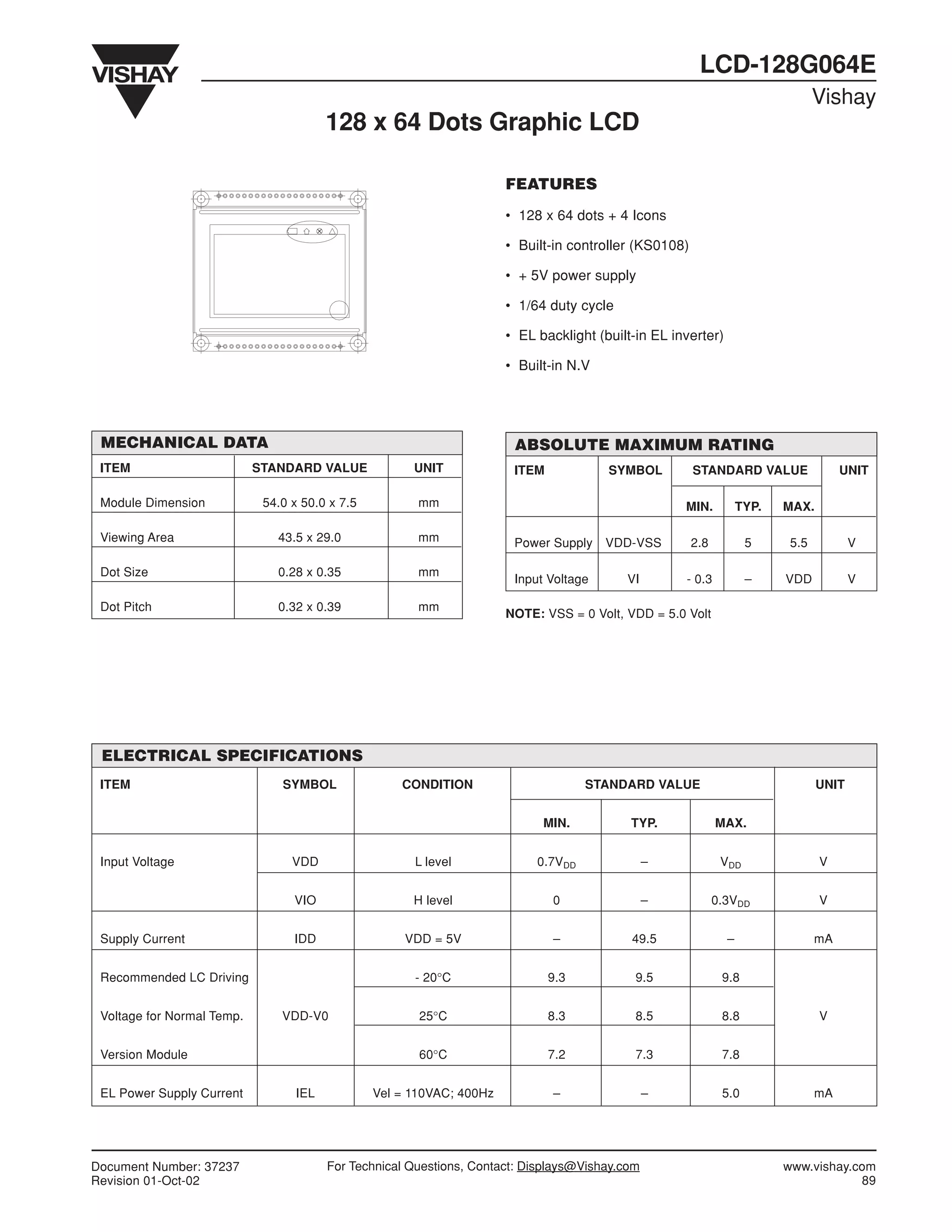
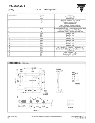
LCD-128G064E
                                                                                                                                  Vishay
                                         128 x 64 Dots Graphic LCD

                                                                       FEATURES
                                                                       • 128 x 64 dots + 4 Icons

                                                                       • Built-in controller (KS0108)

                                                                       • + 5V power supply

                                                                       • 1/64 duty cycle

                                                                       • EL backlight (built-in EL inverter)

                                                                       • Built-in N.V


 MECHANICAL DATA                                                        ABSOLUTE MAXIMUM RATING
 ITEM                       STANDARD VALUE             UNIT             ITEM            SYMBOL          STANDARD VALUE                 UNIT

 Module Dimension            54.0 x 50.0 x 7.5          mm                                           MIN.           TYP.   MAX.

 Viewing Area                  43.5 x 29.0              mm              Power Supply    VDD-VSS         2.8          5      5.5          V

 Dot Size                      0.28 x 0.35              mm
                                                                        Input Voltage      VI        - 0.3           –     VDD           V

 Dot Pitch                     0.32 x 0.39              mm
                                                                       NOTE: VSS = 0 Volt, VDD = 5.0 Volt


 ELECTRICAL SPECIFICATIONS
 ITEM                           SYMBOL               CONDITION                       STANDARD VALUE                               UNIT


                                                                             MIN.           TYP.              MAX.


 Input Voltage                    VDD                  L level              0.7VDD               –             VDD                V


                                  VIO                  H level                 0                 –            0.3VDD              V


 Supply Current                   IDD                 VDD = 5V                 –            49.5                –                 mA


 Recommended LC Driving                                - 20°C                  9.3           9.5               9.8


 Voltage for Normal Temp.       VDD-V0                  25°C                   8.3           8.5               8.8                V


 Version Module                                         60°C                   7.2           7.3               7.8


 EL Power Supply Current           IEL           Vel = 110VAC; 400Hz           –                 –             5.0                mA


Document Number: 37237                   For Technical Questions, Contact: Displays@Vishay.com                             www.vishay.com
Revision 01-Oct-02                                                                                                                     89
LCD-128G064E
Vishay                                                                       128 x 64 Dots Graphic LCD

 PIN NUMBER                                                                          SYMBOL                                                FUNCTION
 1                                                                                     Vss                                              Power Supply (0V)
 2                                                                                     Vdd                                                Power Supply
 3                                                                                     Vo                                      Operating Voltage for LCD Driving
 4                                                                                     D/I                                          Register Selection Input
                                                                                                                                      High = Data Register
                                                                                                                             Low = Instruction Register (for Write)
                                                                                                                             Busy Flag Address Counter (for Read)
 5                                                                                    R/W                            R/W Signal Input is used to Select the Read/Write Mode
                                                                                                                            High = Read Mode, Low = Write Mode
 6                                                                                     E                                 Start Enable Signal to Read or Write the Data
 7                                                                                    DB0                                                 Data Bus Line
 8                                                                                    DB1                                                 Data Bus Line
 9                                                                                    DB2                                                 Data Bus Line
 10                                                                                   DB3                                                 Data Bus Line
 11                                                                                   DB4                                                 Data Bus Line
 12                                                                                   DB5                                                 Data Bus Line
 13                                                                                   DB6                                                 Data Bus Line
 14                                                                                   DB7                                                 Data Bus Line
 15                                                                                   CS1                               Chip Enable for D2 (Segment 1 to Segment 64)
 16                                                                                   CS2                              Chip Enable for D3 (Segment 65 to Segment 128)
 17                                                                                   RST                                                  Reset Signal
 18                                                                                   Vee                                            Power Supply for LCD
 19                                                                                   BL +                                         Enable (on/off) for EL B/L
 20                                                                                   BL -                                                No Connection


 DIMENSIONS in millimeters


                                                                  54.0 ± 0.5
                                    5.25                                                                                7.5 MAX
                       4.75


                                                                    43.5
                                                                                           1.5
                                                                                           2.5


                                    6.54                           40.92                                                          3.3
                                                                                                                                                   0.32
                              11.54
                              10.5


                                                                                                                                                   0.28


                                                                                 A
          50.0 ± 0.5


                                      2.0
                              26.92
                               29.0


                                                                                                                                                  0.39
                                                                                                                                                  0.35
                       40.5


                                                               128*64 DOTS
                                                                                           47.0
                                                                                           45.0


                                                                                B                                                                         DOT SIZE


                                                  8.0         P2.0*19 = 38.0                4 - Ø 2.5                          1.0
                                    2.5                             49.0                    4 - Ø 5.0                  EL or NO B/L
                                                                                             4 - Ø 0.8
                                                                                             4 - Ø 1.3
                        0.1


                                                                 90°           90°
                                                                                      0.
                                                                       1
                                                                       0.


                                                                                       1


                                                                                                   60


                                                                                                               2.0
                        0.7
                        1.8


                                                                                                    °


                                                        1.2
                                                                                                         0.1


                              0.3           2.7                  1.8           1.8           1.9
                                                          3.0          4.0           4.0           4.0                                      DETAIL B

                                                                       DETAIL A


www.vishay.com                                                     For Technical Questions, Contact: Displays@Vishay.com                         Document Number: 37237
90                                                                                                                                                    Revision 01-Oct-02
This datasheet has been download from:

      www.datasheetcatalog.com

Datasheets for electronics components.

Glcd datasheeet

  • 1.
    LCD-128G064E Vishay 128 x 64 Dots Graphic LCD FEATURES • 128 x 64 dots + 4 Icons • Built-in controller (KS0108) • + 5V power supply • 1/64 duty cycle • EL backlight (built-in EL inverter) • Built-in N.V MECHANICAL DATA ABSOLUTE MAXIMUM RATING ITEM STANDARD VALUE UNIT ITEM SYMBOL STANDARD VALUE UNIT Module Dimension 54.0 x 50.0 x 7.5 mm MIN. TYP. MAX. Viewing Area 43.5 x 29.0 mm Power Supply VDD-VSS 2.8 5 5.5 V Dot Size 0.28 x 0.35 mm Input Voltage VI - 0.3 – VDD V Dot Pitch 0.32 x 0.39 mm NOTE: VSS = 0 Volt, VDD = 5.0 Volt ELECTRICAL SPECIFICATIONS ITEM SYMBOL CONDITION STANDARD VALUE UNIT MIN. TYP. MAX. Input Voltage VDD L level 0.7VDD – VDD V VIO H level 0 – 0.3VDD V Supply Current IDD VDD = 5V – 49.5 – mA Recommended LC Driving - 20°C 9.3 9.5 9.8 Voltage for Normal Temp. VDD-V0 25°C 8.3 8.5 8.8 V Version Module 60°C 7.2 7.3 7.8 EL Power Supply Current IEL Vel = 110VAC; 400Hz – – 5.0 mA Document Number: 37237 For Technical Questions, Contact: Displays@Vishay.com www.vishay.com Revision 01-Oct-02 89
  • 2.
    LCD-128G064E Vishay 128 x 64 Dots Graphic LCD PIN NUMBER SYMBOL FUNCTION 1 Vss Power Supply (0V) 2 Vdd Power Supply 3 Vo Operating Voltage for LCD Driving 4 D/I Register Selection Input High = Data Register Low = Instruction Register (for Write) Busy Flag Address Counter (for Read) 5 R/W R/W Signal Input is used to Select the Read/Write Mode High = Read Mode, Low = Write Mode 6 E Start Enable Signal to Read or Write the Data 7 DB0 Data Bus Line 8 DB1 Data Bus Line 9 DB2 Data Bus Line 10 DB3 Data Bus Line 11 DB4 Data Bus Line 12 DB5 Data Bus Line 13 DB6 Data Bus Line 14 DB7 Data Bus Line 15 CS1 Chip Enable for D2 (Segment 1 to Segment 64) 16 CS2 Chip Enable for D3 (Segment 65 to Segment 128) 17 RST Reset Signal 18 Vee Power Supply for LCD 19 BL + Enable (on/off) for EL B/L 20 BL - No Connection DIMENSIONS in millimeters 54.0 ± 0.5 5.25 7.5 MAX 4.75 43.5 1.5 2.5 6.54 40.92 3.3 0.32 11.54 10.5 0.28 A 50.0 ± 0.5 2.0 26.92 29.0 0.39 0.35 40.5 128*64 DOTS 47.0 45.0 B DOT SIZE 8.0 P2.0*19 = 38.0 4 - Ø 2.5 1.0 2.5 49.0 4 - Ø 5.0 EL or NO B/L 4 - Ø 0.8 4 - Ø 1.3 0.1 90° 90° 0. 1 0. 1 60 2.0 0.7 1.8 ° 1.2 0.1 0.3 2.7 1.8 1.8 1.9 3.0 4.0 4.0 4.0 DETAIL B DETAIL A www.vishay.com For Technical Questions, Contact: Displays@Vishay.com Document Number: 37237 90 Revision 01-Oct-02
  • 3.
    This datasheet hasbeen download from: www.datasheetcatalog.com Datasheets for electronics components.