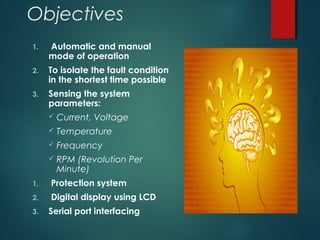
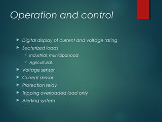
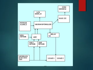
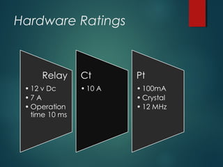
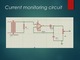
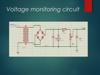
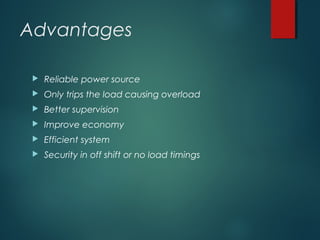
PRESENTATIoPRESENTATIo
NN
Generator fault indicator with auto shut down and
overload control (GSM Based)
Project advisor:
Sir Mirza Shabbir
 Presenter
 Moon Shahzad
5
Contents
 Historical back ground
 Introduction
 Motivation
 Objectives
 Requirements
 Operation and control
 Block diagram
 Over load reasons
 Function of current control circuit
 Hardware
 Applications
 Advantages
 Future aspects
Historical Back ground
 Presently at overload the whole power system is
tripped
 Halt the continuous power supply
 Reducing the efficiency
 Which than require manual procedure to come
back in operation.
Introduction
 Continuous supply
 Overload control
 Auto trip
 Healthy loads stay in operation
 Gsm alert
 Alarming buzzer
 Better supervision
 security
Motivation
 The reason which motivated us toward
this project is that we wanted a digital
control (Microcontroller and Gsm Based)
generator for controlling overload.
Objectives
1. Automatic and manual
mode of operation
2. To isolate the fault condition
in the shortest time possible
3. Sensing the system
parameters:
 Current, Voltage
 Temperature
 Frequency
 RPM (Revolution Per
Minute)
1. Protection system
2. Digital display using LCD
3. Serial port interfacing
Requirements
 circuit Designing of current and voltage control modules.
 Programming of PIC16F877A microcontroller. Designing PCB
for each module.
 Making circuit hardware of modules.
 Assembly of all parts on a single board.
 Finalize checking of the working of all circuit modules.
 Digital display of current and voltage rating
 Secterized loads
 Industrial, municipal load
 Agricultural,
 Voltage sensor
 Current sensor
 Protection relay
 Tripping overloaded load only
 Alerting system
Operation and control
Overload Reasons
 Reasons
 Under voltage
 Short circuit
 Over current
Function of current control
circuit:
 ADC is built in microcontroller to measure the analog
parameter.
 To monitor and display the generator parameters on the
LCD display.
 To monitor the variations in the value of parameters of
generator to determine whether these values exceed the
limit given in the programming.
 When any value of parameter exceed the predefined
limit specific numbed is send to main control unit through
serial port of microcontroller. This number is recognized in
the main control unit to trip the load at overload .
 A LCD is used for displaying the different parameters.
Hardware
 Microcontroller PIC16F877A
 GSM Modem
 Lcd
 Relays
 Crystal
 Integrated circuits
 sensors
1.Current transformer
2.Voltage transformer
3.Rpm sensor
4. MAX232
Hardware Ratings
Hardware Ratings
Current monitoring circuit
Voltage monitoring circuit
Advantages
 Reliable power source
 Only trips the load causing overload
 Better supervision
 Improve economy
 Efficient system
 Security in off shift or no load timings
Applications
Industrial base
Banks, Malls, hospitals
Housing schemes, big complexes
Security agencies
Universities, colleges
National grid
Wapda
Future aspects
Queries

Generator fault indicator with auto shut down and overload control (GSM Based)

  • 2.
    PRESENTATIoPRESENTATIo NN Generator fault indicatorwith auto shut down and overload control (GSM Based)
  • 3.
  • 4.
  • 5.
    5 Contents  Historical background  Introduction  Motivation  Objectives  Requirements  Operation and control  Block diagram  Over load reasons  Function of current control circuit  Hardware  Applications  Advantages  Future aspects
  • 6.
    Historical Back ground Presently at overload the whole power system is tripped  Halt the continuous power supply  Reducing the efficiency  Which than require manual procedure to come back in operation.
  • 7.
    Introduction  Continuous supply Overload control  Auto trip  Healthy loads stay in operation  Gsm alert  Alarming buzzer  Better supervision  security
  • 8.
    Motivation  The reasonwhich motivated us toward this project is that we wanted a digital control (Microcontroller and Gsm Based) generator for controlling overload.
  • 9.
    Objectives 1. Automatic andmanual mode of operation 2. To isolate the fault condition in the shortest time possible 3. Sensing the system parameters:  Current, Voltage  Temperature  Frequency  RPM (Revolution Per Minute) 1. Protection system 2. Digital display using LCD 3. Serial port interfacing
  • 10.
    Requirements  circuit Designingof current and voltage control modules.  Programming of PIC16F877A microcontroller. Designing PCB for each module.  Making circuit hardware of modules.  Assembly of all parts on a single board.  Finalize checking of the working of all circuit modules.
  • 11.
     Digital displayof current and voltage rating  Secterized loads  Industrial, municipal load  Agricultural,  Voltage sensor  Current sensor  Protection relay  Tripping overloaded load only  Alerting system Operation and control
  • 13.
    Overload Reasons  Reasons Under voltage  Short circuit  Over current
  • 14.
    Function of currentcontrol circuit:  ADC is built in microcontroller to measure the analog parameter.  To monitor and display the generator parameters on the LCD display.  To monitor the variations in the value of parameters of generator to determine whether these values exceed the limit given in the programming.  When any value of parameter exceed the predefined limit specific numbed is send to main control unit through serial port of microcontroller. This number is recognized in the main control unit to trip the load at overload .  A LCD is used for displaying the different parameters.
  • 15.
    Hardware  Microcontroller PIC16F877A GSM Modem  Lcd  Relays  Crystal  Integrated circuits  sensors 1.Current transformer 2.Voltage transformer 3.Rpm sensor 4. MAX232
  • 16.
  • 17.
  • 18.
  • 19.
  • 20.
    Advantages  Reliable powersource  Only trips the load causing overload  Better supervision  Improve economy  Efficient system  Security in off shift or no load timings
  • 21.
    Applications Industrial base Banks, Malls,hospitals Housing schemes, big complexes Security agencies Universities, colleges National grid Wapda
  • 22.
  • 24.