


![THM 7025 User's Manual
Conventions
This manual uses the following conventions:
<HOLD> : name of a keyboard button.
[ENQ] : a RS 232c command.
"BAT" : an indication in the display.
'1' : a parameter or option.
200 : a string of characters returned by the THM 7025.
METROLAB Instruments SA 1](https://image.slidesharecdn.com/gaussmetrothm7025-usermanual-110628094843-phpapp01/85/Gaussmetro-thm7025-user-manual-5-320.jpg)


![THM 7025 User's Manual
This function is recalled on the keyboard by ALWAYS ON
The [OFF] command can cancel or enable the automatic switch Off.(See section
5.11, page 18.)
Also, when the battery is too low, the display indicates "BAT" and a few minutes
later, the THM 7025 switches Off by itself.
4.3. RANGE
The values of measurement are displayed in three ranges :
1. 19.99 mT
2. 199.9 mT
3. 1999 mT.
When the THM 7025 is switched On, it is set on autoranging mode and it
displays the measurement in the most appropriate range. By pressing
<RANGE>, it switches from Autoranging to 1999, by second pressing to 199.9,
by third pressing to 19.99 and then switches back to autoranging mode. Before
displaying the value of the magnetic field, the THM 7025 displays the selected
range for a half second. Refer to the following chart:
Pressure on Range of Range indication in
<RANGE> measurement the display
When switched On Autoranging
1st up to 1999 0
2nd up to 199.9 0.0
3rd up to 19.99 0.00
4th Autoranging Aut.
...
4.4. Bz (B on Z axis)
The <Bz> button toggles between 3 and single axis measurements. To
distinguish between these two modes, the sign "+" or "-" is displayed with the
magnetic field value in single axis mode. Otherwise no sign is displayed.
By default, the chosen axis is 'Z'. The access to another axis is possible via the
RS 232c command [BZA] (see section 5.7, page 15).
When switched On : 3 Axis measurement
Press once : measurement of a single axis (Z) (display of "+" or "-")
Press again : comes back to 3 Axis measurement
10 METROLAB Instruments SA](https://image.slidesharecdn.com/gaussmetrothm7025-usermanual-110628094843-phpapp01/85/Gaussmetro-thm7025-user-manual-14-320.jpg)
![THM 7025 User's Manual
5. INTERFACE RS 232c COMMANDS
5.1. INTRODUCTION
Ensure the instrument is Off before connecting the supplied RS 232c cable from
the THM 7025 to the serial port of the computer.
Set the computer with the following RS 232c parameters :
9600 bauds, 8 bits, no parity, 1 stop bit, No XON/OFF.
The control of the THM 7025 through the serial interface is made with a set of
commands. Every command consist of a string of ASCII characters using the
following syntax: a root of 3 mnemonic characters then one or zero parameters,
then the characters 'carriage-return' (ASCII 13) and 'Line-feed' (ASCII 10).
The root and the parameter are separated by a comma.
Note: the characters 'carriage-return' - 'line-feed' are mandatory for any
command, as well as they are returned at the end of any string of
characters sent by the THM 7025. However, to clarify the text, they have
been omitted in the command description.
Some commands are 'read only' (ex: [ENQ]), or 'write only' (ex: [CLE]). The
others are 'read and write' commands. They are used to set a parameter or an
option. In 'write' mode these commands include the parameter (ex: [RNG,2]) and
in 'read' mode these commands have no parameter (ex: [RNG]) and the present
parameter value is returned by the THM 7025.
The set of commands is described in the following sections.
5.2. ENQ (ENQuire displayed value)
The [ENQ] Command returns the value of the magnetic field.
The returned string of characters corresponds to the display. This command will
return the field value presently displayed. If the THM 7025 is overloaded, the
[ENQ] Command will return: O.L.
If the [ENQ] Command is sent when the THM 7025 is changing the range of
measurement (display reads " - - - "), the returned string of characters will be: !
The [ENQ,n] Command gives the value of the magnetic field of the individual
axis, where :
n = 1 for X Axis
n = 2 for Y Axis
n = 3 for Z Axis
Note: if the THM 7025 is in single axis mode, [ENQ] will return the magnetic field
value of this axis only. Whereas [ENQ,n] will return 0 if 'n' refers to one of
the none-selected axis.
METROLAB Instruments SA 13](https://image.slidesharecdn.com/gaussmetrothm7025-usermanual-110628094843-phpapp01/85/Gaussmetro-thm7025-user-manual-17-320.jpg)
![THM 7025 User's Manual
5.3. RNG (RaNGe)
The [RNG,n] Command modifies the ranges of measurement where :
n = 1 or 20 sets 19.99 mT range
n = 2 or 200 sets 199.9 mT range
n = 3 or 2000 sets 1999. mT range
n=0 sets in autoranging mode.
The [RNG] Command returns the current status of range in a string of characters
which has the following meaning :
0 for the autoranging mode
20 for the 19.99 mT range
200 for the 199.9 mT range
2000 for the 1999. mT range.
5.4. HLD (HoLD)
The [HLD,n] Command holds or releases the display where :
n = 1, display is held
n = 0, display is running.
The [HLD] Command returns the current status of Hold mode.
The [HLD,n] Command alternates normal and toggle operation of the button,
where :
n = 2, button <HOLD> is in toggle operation
n = 3, button <HOLD> is in normal operation.
(see section 4.5 at page 11 on how to use button <HOLD>).
Note : The selected operation, normal or toggle, is memorised. The chosen
operation remains after switching off the THM 7025.
5.5. MAP
The [MAP,n] Command sends to RS 232c the displayed value where :
n = 1, at each press of button <HOLD> the displayed value is sent to
RS 232c
n = 0, release MAP function.
Note : Thanks to the RS 232c interface, the mapping of a field is very convenient.
The THM 7025 is positioned where a measurement of the field has to be
taken. When the user is pressing the button <HOLD>, the displayed value
is sent to the computer, thus allowing easy acquisition of magnetic field
values.
14 METROLAB Instruments SA](https://image.slidesharecdn.com/gaussmetrothm7025-usermanual-110628094843-phpapp01/85/Gaussmetro-thm7025-user-manual-18-320.jpg)
![THM 7025 User's Manual
5.6. STZ (Set To Zero)
The [STZ,n] Command deals with the sensor offsets, where:
n = 1, measures and memorizes the User's Offset on the three axis.
This Command has the same result as by pressing down the buttons <ZERO>
and <HOLD> (See section 4.6, page 11)
WARNING : to measure the User's Offset, the user has to place the probe in the
zero field chamber which itself must be in a magnetic environment
below 0.15 mT (1.5 Gauss or about ~3 time the Earth magnetic field
strength).
n = 0, reverts to System Offset.
This Command has the same result as by pressing down the buttons <ZERO>
and <ON/OFF>. (See section 4.6, page 11)
The [STZ] Command returns 0 if THM 7025 is being used with System Offset or
returns 1 if it is being used with User's Offset.
5.7. BZA (B on single Axis)
This command allows the user to select any of the three single axis or the 3 axis
mode.
The [BZA,n] Command sets the Axis mode where :
n = 1, for the X axis
n = 2, for the Y axis
n = 3, for the Z axis
n = 0, for the 3 axis mode.
Note: by pressing the <Bz> button, the display indicates the magnetic field
measured with the last single axis selected by the [BZA] Command.
The [BZA] Command returns the current status of the axis mode.
5.8. VER (firmware VERsion)
The [VER] Command returns the firmware version in the following string of
characters.
METROLAB SA, THM 7025, Ver X.XX
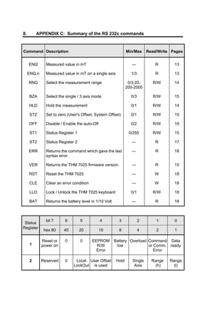
5.9. ST1 (STatus register 1)
The [ST1] Command returns the Status Register 1
METROLAB Instruments SA 15](https://image.slidesharecdn.com/gaussmetrothm7025-usermanual-110628094843-phpapp01/85/Gaussmetro-thm7025-user-manual-19-320.jpg)
![THM 7025 User's Manual
The Status Register 1 is returned in a string of 8 ASCII characters 0 or 1 followed
by 'CR' 'LF'; the first character received is the most significant bit (bit 7).
The [ST1,n] Command clears the bits of the Status Register 1
Where 'n' is a decimal value from 0 to 255 which allows to write zeroes in Status
Register 1: i.e. '0' clears all bits of the Status Register 1; '255' doesn't clear any
bits of the Status Register 1; '9' clears all bits except the bits 3 and 0 of the
Status Register 1.
Meaning of the status register 1:
7 6 5 4 3 2 1 0
Reset or 0 0 EEPROM Battery Overload Command Data
power on R/W low or Com. ready
Error Error
Bit 7: reset or power on
This bit is set to 1 at power on or by a reset of the instrument using the [RST]
Command.
Bit 6: always 0
Bit 5: always 0
Bit 4: EEPROM Read/Write error
This bit is set to 1 to indicate that there is an error in reading or writing
parameters in the none-volatile memory (EEPROM). This is a fatal error which
cannot be cleared. The instrument needs to be repaired.
Bit 3: Battery low
This bit is set to 1 to indicate that the battery level is too low and thus the battery
needs to be changed. The display reads "BAT".
Bit 2: Overload
This bit is set to 1 to indicate that the range is overloaded. The display reads
"O.L." . The user can select a higher range, if it is possible.
Bit 1: Command or communication error
This bit is set to 1 to indicate that the syntax of a command was wrong. The last
command which gave the error is returned by the [ERR] Command.
This bit is also set in case of an error in the communication with the RS 232c
interface.
Bit 0: Data ready
This bit is set to 1 to indicate that a value is available for reading. The update
interval is about 0.4 sec.
16 METROLAB Instruments SA](https://image.slidesharecdn.com/gaussmetrothm7025-usermanual-110628094843-phpapp01/85/Gaussmetro-thm7025-user-manual-20-320.jpg)
![THM 7025 User's Manual
5.10. ST2 (STatus register 2)
The [ST2] Command returns the Status Register 2.
The Status Register 2 is returned in a string of 8 ASCII characters 0 or 1 followed
by 'CR' 'LF'; the first character is the most significant bit (bit 7). The bit of the
Status Register 2 indicate the state of the instrument at the moment of the reading.
They cannot be cleared by the user.
Meaning of the status register 2:
7 6 5 4 3 2 1 0
Reserved 0 Local User's Hold Single Range Range
or LockOut Offset is Axis (h) (l)
1 used
Bit 7: Reserved
Bit 6: 0 or 1
Can be 0 or 1. Information used at the factory only (test and diagnostic purposes).
Bit 5: Local LockOut
This bit is set to 1 when the keyboard is locked.
It is cleared to 0 when it is in operation.
Bit 4: User's Offset
This bit is set to 1 when the THM 7025 is used with the User's Offset.
It is cleared to 0 when it is used with the System Offset.
Bit 3: Hold
This bit is set to 1 when the display is held.
It is cleared to 0 when the display is running.
Bit 2: Single axis
This bit is set to 1 when the THM 7025 is used in single axis mode.
It is cleared to 0 when the 3 axis mode is activated.
Bits 1 and 0: Ranges
These bit indicate the range:
Bit 1 Bit 0 RANGE
0 0 not available *
0 1 20.00 mT
1 0 200.0 mT
1 1 2000. mT
* Combination of 0 and 0 cannot occur.
METROLAB Instruments SA 17](https://image.slidesharecdn.com/gaussmetrothm7025-usermanual-110628094843-phpapp01/85/Gaussmetro-thm7025-user-manual-21-320.jpg)
![THM 7025 User's Manual
5.11. OFF (auto OFF)
The [OFF,n] Command controls the automatic switch Off function:
n = 0, mode auto-OFF is canceled. The THM 7025 is On until it is
switched Off by using the button <ON/OFF> or the [OFF,2]
Command. The display reads " On " for ~0.4 sec.
n = 1, mode auto-OFF is enabled, meaning that the THM 7025 will be
automatically switched Off by itself after 3 minutes when unused.
The display reads " OFF " for ~0.4 sec.
n = 2, the THM 7025 is switched Off !
5.12. BAT (BATtery Level)
The [BAT] Command returns the current battery level in 1/10 of Volts.
Example : 92 indicates 9.2 V
5.13. RST (ReSeT)
The [RST] Command resets the THM 7025.
The THM 7025 returns to the same status as when it has been switched On.
5.14. LLO (Local LockOut)
The [LLO,n] Command blocks or releases the keyboard.
It presents a safety if the user does not want to loose the parameters which he
has modified, by touching accidentally the keyboard of the unit.
n = 1, the keyboard is locked
n = 0, the keyboard is in operation.
5.15. ERR (ERRor)
The [ERR] Command returns the first 3 digits of the last command which gave a
syntax error.
The syntax error is indicated by bit 1 of status register 1.
18 METROLAB Instruments SA](https://image.slidesharecdn.com/gaussmetrothm7025-usermanual-110628094843-phpapp01/85/Gaussmetro-thm7025-user-manual-22-320.jpg)
![THM 7025 User's Manual
5.16. CLE (CLear Error)
The [CLE] Command clears an eventual error.
i.e. : when the display reads "Er.2" or "Er.3"
Errors description:
If a fault is detected, the Display or the returned string of characters of the [ENQ]
command indicates "Er.n", where :
n = 1, This is an error in reading or writing the parameters in the none-
volatile memory (EEPROM).
This is a fatal error which cannot be cleared and the instrument
needs to be repaired.
n = 2, This error arises when there is a fault in the RS 232c communication
or the reading of the keyboard.
This error can be cleared by either pressing button <ZERO> or
by using the [CLE] Command.
n = 3, This error occurs either during a User's Offset measurement, when
the residual magnetic field is too high to be nulled.
The error 3 can be cleared by either pressing button <ZERO>
or by using the [CLE] Command.
METROLAB Instruments SA 19](https://image.slidesharecdn.com/gaussmetrothm7025-usermanual-110628094843-phpapp01/85/Gaussmetro-thm7025-user-manual-23-320.jpg)
![THM 7025 User's Manual
The range 1999 mT is selected.
The range 199.9 mT is selected.
The range 19.99 mT is selected.
The THM 7025 returns to the System Offset.
The User's Offset is being measured and memorized.
B) Error messages (They are displayed until the error condition is cleared):
The range is overloaded, the user can select the higher range, if
it is possible.
This is an error in reading or writing the parameters in the none-
volatile memory (EEPROM).
This is a fatal error which cannot be cleared and the
instrument needs to be repaired.
This error arises when there is a fault in the RS 232
communication or the reading of the keyboard. It can be cleared
by either pressing button <ZERO> or by using the command
[CLE].
This error occurs either during a User's Offset measurement,
when the residual magnetic field is too high to be nulled,
or during regular measurements, when the internal memory is
saturated. However, the latter should never occur in normal
operation. This error can be cleared by either pressing button
<ZERO> or by using the [CLE] Command.
22 METROLAB Instruments SA](https://image.slidesharecdn.com/gaussmetrothm7025-usermanual-110628094843-phpapp01/85/Gaussmetro-thm7025-user-manual-26-320.jpg)

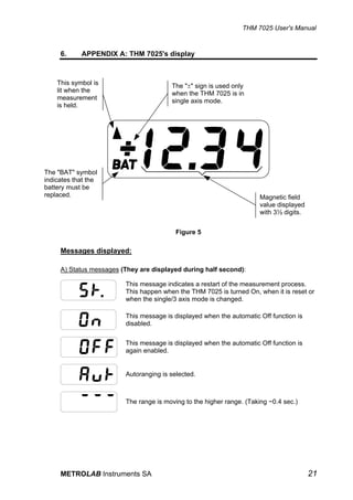
This document provides user instructions for the METROLAB THM 7025 3-axis Hall teslameter. It includes sections on general description, specifications, safety, principles of operation including the user interface buttons, and RS-232 interface commands. The document contains detailed information on operating the instrument and programming it via its serial communication interface.


![Gu641 B Genset Control Operation Manual[1]](https://cdn.slidesharecdn.com/ss_thumbnails/gu641bgensetcontroloperationmanual1-13324716217433-phpapp02-120322220238-phpapp02-thumbnail.jpg?width=640&height=640&fit=bounds)


