Download to read offline

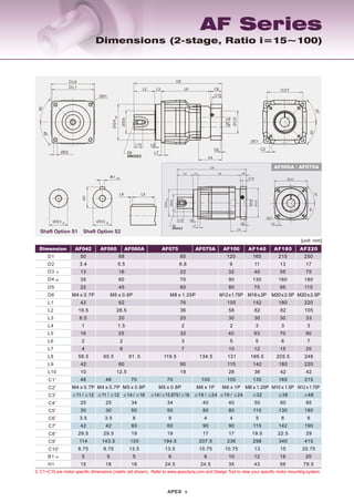
![Dimensions (1-stage, Ratio i=3~10)
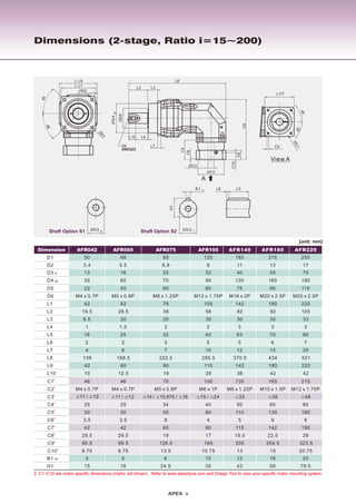
1. C1~C10 are motor specific dimensions (metric std shown). Refer to www.apexdyna.com and Design Tool to view your specific motor mounting system.
2. AF042 ratio 5, 10 offers C3 ≤ 12 option; AF062 ratio 5, 10 offers C3 ≤ 16 option.
[unit: mm]
D1
D2
D3 j6
D4 g6
D5
D6
L1
L2
L3
L4
L5
L6
L7
L8
50
3.4
13
35
22
42
19.5
6.5
1
16
2
4
31
46
M4 x 0.7P
25
30
3.5
42
29.5
86.5
8.75
5
15
68
5.5
16
60
45
62
28.5
20
1.5
25
2
6
54.5
70
M5 x 0.8P
34
50
8
60
19
122
13.5
5
18
165
11
40
130
75
142
82
30
3
63
5
12
110
165
M10 x 1.5P
60
130
6
142
22.5
244.5
15
12
43
215
13
55
160
95
180
82
30
3
70
6
15
150
215
M12 x 1.75P
85
180
6
190
29
291
20.75
16
59
250
17
75
180
115
220
105
33
3
90
7
20
163.5
235
M12 x 1.75P
116
200
6
220
63
364.5
53
20
79.5
C1
1
C2
1
C31
C41
C51
C61
C7
1
C8
1
C91
C101
B1 h9
H1
120
9
32
90
80
105
58
30
2
40
5
10
89.5
130
M8 x 1.25P
50
110
5
115
19.5
197
13
10
35
85
6.8
22
70
60
76
36
20
2
32
3
7
86.5
100
M6 x 1P
40
80
4
90
17
159.5
10.75
6
24.5
≤38 ≤48 ≤55≤32
Dimension AF042 AF060 AF140 AF180 AF220AF075 AF100
L9
L10 10 12.5 36 42 422819
42 60 142 180 22011590
M4 x 0.7P M8 x 1.25P M20 x 2.5P M20 x 2.5PM12 x 1.75P M16 x 2PM5 x 0.8P
≤19 / ≤24
Shaft Option S2
B1 h9
ØD3 j6
Shaft Option S1 ØD3 j6
H1
L5L6
L9
L1
45°
45°
ØD1
ØD2
ØD4g6
ØD5
C4
C6
L7
L4L10
C9
L2 L3 L8 C8
C10
D6
DIN332/2
ØC3
ØC5
ØC1
45°
45°
C2
C7
≤11 / ≤122
≤14 / ≤162](https://image.slidesharecdn.com/afafr-eng-161106120206/85/AF-APEX-DYNAMICS-4-320.jpg)


This document provides specifications for precision taper roller bearing gearboxes from APEX Dynamics. It describes features of their AF and AFR series gearboxes such as lubricated and sealed designs that are maintenance free, heat treated components for wear resistance, helical and planetary gear designs for load capacity and smooth operation, and sealing systems to prevent leakage. Tables provide details on models, specifications, dimensions, performance parameters like output torque and speed ratings, and ordering information. In summary, it presents technical information on industrial gearboxes from APEX Dynamics focusing on design features, specifications, and performance capabilities.


