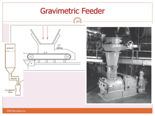
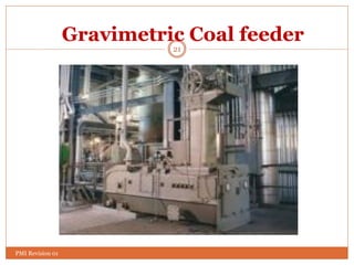
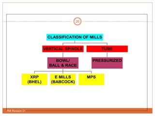
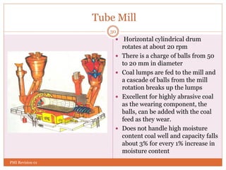
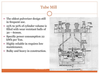
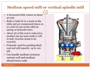
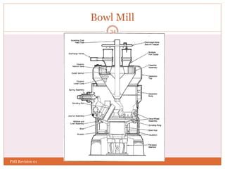
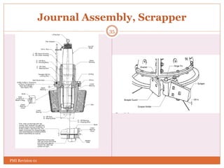
Fuel Firing System
1
PMI Revision 01
2
CONTENTS
 Fuel Oil System & Oil Burners
 Feeders
 Coal Pulverizers
 Coal Burners
PMI Revision 01
Fuel Oil System
Purpose:
 to establish initial boiler light up.
 to support the furnace flame during low load
operation.
PMI Revision 01
3
Objective is to get filtered oil at
 correct pressure
 correct temperature
4
Fuel Oil System
 Fuel oil system Consists of
Fuel Oil Pumps
Oil heaters
Filters
Steam tracing lines
PMI Revision 01
5
Atomization
 Atomization breaks the fuel into fine
particles that readily mixes with the air for
combustion. Oil should be divided up into
small particles for effective atomization
 The advantages of atomization are:
a) Can be used with heavier grades of oil
b) Can be adopted to large applications
because of large capacity range
c) Complete combustion is assured by the
increasing the surface area and mixing
with oxidant
PMI Revision 01
6
Oil Burners
Oil burners are classified according to the method
used for atomization, as follows:
a) Air-atomized burners
b) Steam-atomized burners
c) Mechanically atomized burners
Air atomizing system are not recommended for
heavy oil system as they tend to chill the oil and
decrease atomization quality
PMI Revision 01
7
Steam Atomization
This System uses auxiliary steam to assist in the atomization
of the oil. The steam used in this method should be slightly
superheated and free of moisture. As in the air atomizing
system, the steam used for atomizing as well as heating the
fuel as it pass through the tip and into the furnace.
The main advantages of steam atomizing burners over other
are:
a) Simplicity of its design
b) Initial cost of installation is low
c) Low pumping pressure
d) Low preheating temperature.
Disadvantage is steam used in atomizing process increases
the flue gas volume
PMI Revision 01
8
Oil Burners
The types of oil used in the oil burners are:
a) Light Diesel oil
b) Heavy fuel oil
c) Low sulfur heavy stock (LSHS)
Heavy oil guns are used for stabilizing flame at low
load carrying. Warm up oil guns are used for cold
boiler warm up during cold start up and igniter are
used for start up and oil flame stabilizing.
PMI Revision 01
9
Oil Guns
The guns used in this
system have two main
components for
atomization. They are:
a) Mixing plate
b) Spray Plate
PMI Revision 01
10
Oil Gun Compartment
PMI Revision 01
Low NOx Oil Burners Internals
Staged Air Low NOx Burner
11
PMI Revision 01
Low NOx Oil Burner Internals
Staged Air Low NOx Burner
12
PMI Revision 01
Low NOx Oil Burner
13
PMI Revision 01
Low NOx Oil Burner…
Internal view
14
PMI Revision 01
Low NOx Oil Burner
15
PMI Revision 01
Low NOx Oil Burner Fitted with Boiler
16
PMI Revision 01
17
Coal Feeder & Mill
PMI Revision 01
18
Components
The Major components are :
 Coal Preparation Equipments
 Feeders
 Mills
 Coal Firing Equipments
 Burners
PMI Revision 01
19
Feeders
 Volumetric Type feeder
 Chain Feeder
 Belt Feeder
 Table type belt Feeder
 Gravimetric Feeder
Chain
Feeder
PMI Revision 01
20
Gravimetric Feeder
PMI Revision 01
21
Gravimetric Coal feeder
PMI Revision 01
22
Internals of coal feeder
PMI Revision 01
23
Features of a Feeder
•Two spring-loaded take-up screws adjust belt tension and
tracking.
•A counterweighted scraper
•Mild steel skirting is on three sides of the feeder inlet to
contain material on belt.
•A 3/8" thick mild steel, replaceable leveling bar is furnished
at the feeder inlet to establish the height of material on belt.
•Two (2) load cells are provided, supporting each end of the
weigh roller.
PMI Revision 01
24
Why Pulverized Fuel?
The economic motives for the introduction and
development of pulverized fuel firing are:
 Efficient utilization of cheaper low grade coals.
 Flexibility in firing with ability to meet
fluctuating loads.
 Better response to automatic control.
 Ability to use high combustion air temperature;
increasing the overall efficiency of boiler.
 High availability.
PMI Revision 01
25
Role of Mills
 Produces Pulverized coal 70-75 % of which
passes through 200 mesh
 Air mixed with Pulverized coal (PF) is carried to
the coal nozzle in the wind box assembly
 PF from coal nozzle is directed towards the
centre of boiler burning zone
 Pre-heated secondary air enters boiler and
surrounds the PF and help in combustion
PMI Revision 01
26
XRP
(BHEL)
E MILLS
(BABCOCK)
MPS
BOWL/
BALL & RACE
VERTICAL SPINDLE
PRESSURIZED
TUBE
CLASSIFICATION OF MILLS
PMI Revision 01
27
Classification-As per Speed
Types of Mills
Medium Speed High Speed
Low Speed
17 to 20 Rev/min 30 to 100 Rev/min 500 to 1000 Rev/min
Tube and ball mill Bowl Mill, Ball and
Race mill
Beater Mill, Impact
Mill
PMI Revision 01
Purpose of the Pulverizer
 Reduce the coal to small particles by grinding for
better combustion
 Dry the coal
 Classify the particle size of the coal leaving the mill
 Transport the coal from the classifier to the exhauster
28
PMI Revision 01
TYPES OF COAL PULVERIZER
 Tube or ball mills:
 Low-speed machines that grind the coal with steel balls in a rotating
horizontal cylinder. If the diameter of the cylinder is greater than the length
of the cylinder, the mill is called a ball mill. If the length of the cylinder is
greater than the diameter of the cylinder, it is called a tube mill.
 Vertical spindle mill:
 Medium-speed machines that include bowl mills, ring roll mills, and ring
and ball mills. The bowl mills are further divided into deep bowl or shallow
bowl mills.
 Impact mill:
 High-speed impact machines that use beater wheels to crush the coal
29
PMI Revision 01
Tube Mill
 Horizontal cylindrical drum
rotates at about 20 rpm
 There is a charge of balls from 50
to 20 mm in diameter
 Coal lumps are fed to the mill and
a cascade of balls from the mill
rotation breaks up the lumps
 Excellent for highly abrasive coal
as the wearing component, the
balls, can be added with the coal
feed as they wear.
 Does not handle high moisture
content coal well and capacity falls
about 3% for every 1% increase in
moisture content
30
PMI Revision 01
Tube Mill
 The oldest pulverizer design still
in frequent use.
 25% to 30% of cylinder volume is
filled with wear resistant balls of
30 – 60mm.
 Specific power consumption 22
kWh per Ton.
 Highly reliable in requires low
maintenance.
 Bulky and heavy in construction.
31
PMI Revision 01
Coal Pulverizer System
32
PMI Revision 01
Medium speed mill or vertical spindle mill
 A horizontal table rotates at about
50 rpm
 Rolls or balls lie in a track on the
table and are compressed down on
to a bed of coal on the table by
spring or hydraulic force
 About 5% of the coal is reduced to
product size per pass under a roll
or ball. Oversize needs to be
recycled.
 Primarily used for grinding black
coal and mill capacity up to 100
tph
 Can handle medium moisture
content well and medium
abrasiveness coals
33
PMI Revision 01
Bowl Mill
34
PMI Revision 01
Journal Assembly, Scrapper
35
PMI Revision 01
Raymond Bowl Mill Capacities and Motor Sizes
42.4
45.4
48.3
t/hr
36
PMI Revision 01
High speed mill
 Horizontal shaft rotates at
about 1000 rpm
 Has a series of hammers or
wear bars attached
 All feed material is not reduced
to product size in a single pass
and multiple hammers are used
 Used for grinding brown coal
and lignite where the mill
capacities are high
 Handles high moisture content
well but excessive wear takes
place with high abrasiveness
coals.
37
PMI Revision 01
Impact Mill
38
PMI Revision 01
PULVERIZING PROPERTIES OF COAL
 Grindability is defined as the ease with which the
coal can be pulverized. This should not be confused
with hardness. Coal of the same hardness may have a
range of different grindability indices because of
other constituents, such as moisture.
 A standard index has been developed based on use of
the Hardgrove Grindability machine and is called the
Hardgrove Grindability Index
39
PMI Revision 01
Hardgrove Grindability Index
 The HGI was developed in the 1930s to measure
empirically the relative difficulty of grinding coal to
the particle size necessary for relatively complete
combustion
 The HGI test tries to mimic the operation of a ball
and track type of industrial coal pulverizer
manufactured by Babcock. It does this using a batch
mode of operation compared with a dynamic
situation in an industrial coal pulverizer.
40
PMI Revision 01
HGI test procedure
A 50 gm sample of coal, which has
been prepared in a specific manner
and which has a limited particle size
range, 1.18 x 0.6 mm, is placed in a
stationary grinding bowl in which
eight steel balls can run in a circular
path. A loaded ring is placed on top
of the set of balls with a gravity load
of 284 N. The machine is run for 50
revolutions. The top is removed and
the ground coal removed. This coal
is sized and the quantity less than
75 microns recorded. This is
converted to a HGI value using a
calibration graph
41
PMI Revision 01
Standards for measurement of HGI
AS 1038 Part 20:2002, Hardgrove Grindability of coal
ASTM D 409-2006, Grindability of coal by the Hardgrove
machine method
ASTM D5003-06a, Hardgrove Grindability for petcoke
BS 1016-1981 Part 20, Hardgrove Grindability
DIN 51742-2001, Determination of HGI of hard coal
ISO 5047 1994, Hard coal-Determination of HGI
GOST 15489-93, Hard coal-Determination of HGI
JIS M8861-1993, Determination of HGI
42
PMI Revision 01
Coal Preparation Method affects Results
Testing as per different
standards may result in
commercially significant
differences in the value of
HGI for a specific coal. Such
as ASTM procedure can be
higher than values using AS
procedure on the same coal
sample. The differences
generally lie in the allowed
method of preparing the
sample before testing.
43
PMI Revision 01
Characteristics of HGI
 Has a relatively low reproducibility
and repeatability leads to ambiguity
in evaluating mill performance and
coal properties.
 Exhibits a non linear change in
difficulty to grind.
 Coals with low values of HGI are
more difficult to grind and high
values are much easier to grind.
 HGI of a blend is not necessarily the
weighted sum of the component
coals
 When combined with coal reactivity
or volatile matter, to provide
guidance on likely combustion/
reaction performance
44
PMI Revision 01
Mill capacity vs HGI
 The mill capacity falls when
grinding coal with a lower HGI
 The curve shows variation in
mill capacity with HGI with
100% capacity being nominally
set at HGI of 50.
45
PMI Revision 01
Fineness vs mill capacity
at constant HGI
Mill power vs HGI at
constant fineness
Fineness and Mill Power
HGI is seen as a good measure of the difficulty of grinding coal for coals
with fairly standard properties
46
PMI Revision 01
HGI limitations
 Coals with a moisture content of less than about 10% behave in an
expected manner. However as moisture content increases the HGI
becomes less effective as a predictor
 There is an envelope of coal properties within which HGI is reliable.
This envelope is not well defined.
 HGI does not provide direct information on the likely wear rates of
critical mill grinding components.
 The primary shortcoming of the test is the use of a batch
process
 The test uses sample feed with a limited range of particle sizes,
1.18 x 0.6 mm, rather than a complete range of sizes.
 Other measures of coal grindability: Used for grindability of
minerals in general is the Bond Work Index uses a pilot scale wet
ball mill. Not precise enough for use with coal
47
PMI Revision 01
ROLE OF HGI IN PULVERIZER PERFORMANCE
 It is normal to define the output of a coal pulverizer in
terms of the rate of coal produced and the particle
size distribution of this product.
 The accepted standard for defining the output of an
pulverizer is output in tonnes/hour with a particle
size defined by 70% less than 75 microns and 99.5%
less than 300 microns when grinding with a HGI of
known value. Mostly it is 50. This value has no
critical importance other than to provide a value
against which mill capacity is defined.
48
PMI Revision 01
 Coal pulverizer manufacturers provide sets of curves
linking actual performance of the mill with coal with
different properties such as HGI, moisture content % and
feed particle top size. These curves enable results of a test
on a particular coal to be referenced back to the standard
conditions to monitor the performance of the pulverizer.
 Measurement of the HGI and using the mill manufacturer’s
curves will provide a first estimate of the performance of a
mill with the coal in question when evaluating pulveriser
performance with new coal.
ROLE OF HGI IN PULVERIZER PERFORMANCE
49
PMI Revision 01
Coal properties complementary to HGI
 Pulverized coal with 70% less than 75 microns and 99.5%
less than 300 microns was recognized as being appropriate
for normal conditions, based upon coal with a medium
volatile matter content or reactivity, which results in
reasonable burnout of coal particles, 98–99%, in a well
designed boiler furnace.
 If the volatile matter content or reactivity is higher than
normal, then coal particles somewhat larger will burn out
successfully in the normal furnace volume. This coarser
product requirement allows the mill to provide more
output. Alternatively it allows the use of coal with a lower
HGI with effective particle burnout.
50
PMI Revision 01
Fineness
 Fineness is an indicator of the
quality of the pulverizer action.
Specifically, fineness is a
measurement of the percentage of
a coal sample that passes through a
set of test sieves usually designated
at 50, 100, and 200 mesh.
 A 70% coal sample passing through
a 200 mesh screen indicates
optimum mill performance. Values
greater than 70% require the mill
to perform more work. The mill
wear and the power onsumption
are increased if the 70% value is
exceeded. Values lower than 70%
mean higher carbon loss and
increased fuel consumption.
51
PMI Revision 01
Coal Finess
 Coal retained on the 50 mesh
screen should be in the 1–2%
range. Higher values indicate
worn internals or improper
settings. Also, the higher
percentages can cause boiler
slagging and high unburned
carbon
 The 50 mesh screen is an
indication of relative coarseness.
The 100 mesh screen indicates an
unsuccessful test, and the 200
mesh screen indicates relative
fineness.
52
PMI Revision 01
Relationship between grindability and mill capacity
53
PMI Revision 01
Moisture and Grindability Effects on Mill Capacity
54
PMI Revision 01
55
Coal Burner
PMI Revision 01
56
Firing System
 Direct Firing System: Coal is fed to the mill at controlled
quantity. Hot air (temperature controlled) is permitted to
flow through the mill. The air dries the coal and picks up the
milled product and flows through the classifier rejecting
higher size particle. The fine coal is carried through the coal
burner to the combustion chamber.
 Indirect Firing System: Mills are operated independent
of boiler loading and pulverized coal is stored in the
intermediate bunker. From the bunker it is taken to
combustion chamber with the help of primary air fan. Boiler
loading is controlled by the amount of pulverized fuel fed to
boiler.
PMI Revision 01
57
Direct Firing
PMI Revision 01
58
Indirect Firing
PMI Revision 01
59
Coal Burners
• Coal burners comprise of coal nozzle, steel tip, seal plate
and tilting link mechanism.
• Housed in coal compartment in all four corners of the
furnace and connected with coal pipes.
•One end (outlet) is rectangular and another end is
cylindrical.
•The burner can be tilted on a pivot pin
•. The nozzle tip has separate coal and air passages.
• Coal and air passages is divided into several parts
PMI Revision 01
60
Methods of Fuel Firing
 Vertical Firing : A number of rectangular fan shaped
nozzles are set across the width of the furnace in an arch.
Pulverized fuel mixture ignites under the arch and is
directed vertically downwards to the bottom of the
furnace where the gases are made to turn upwards to pass
through the combustion chamber this gives a long path to
the flame and is particularly suitable for coals of low
volatile content.
 Horizontal Firing: Horizontal firing with the turbulent
type of burner are set up usually in the front (front wall
fired) or rear walls of the furnace. Burner consists of an
inner cone for primary air and fuel which is given a rotary
motion as it passes through the burner.
PMI Revision 01
61
Methods of Fuel Firing
 Impact Firing : This is the arrangement with the
type of burner used with slag tap furnaces where
the ash is kept in a molten state on the furnace
floor and tapped off as and when necessary.
 Corner or tangential Firing: Burners are set at
each corner of the furnace and are directed to
strike the outside of an imaginary circle in the
centre of the furnace.
PMI Revision 01
62
Tangential Firing System
PMI Revision 01
63
Tangential Firing Burner Arrangement
PMI Revision 01
Tangentially Fired Coal Burner
Burners Outlets
Wind box Connection
64
PMI Revision 01
65
Low NOx Coal Burner
PMI Revision 01
Low NOx Coal
Burner…Flame Structure
66
PMI Revision 01
Low NOx Coal Burner…
Internal View
67
PMI Revision 01
68
Low NOx Coal Burner Details
PMI Revision 01
69
Low NOx Coal Burner Details contd.
PMI Revision 01
70
PMI Revision 01

Fuel Firing System.pdf

  • 1.
  • 2.
    2 CONTENTS  Fuel OilSystem & Oil Burners  Feeders  Coal Pulverizers  Coal Burners PMI Revision 01
  • 3.
    Fuel Oil System Purpose: to establish initial boiler light up.  to support the furnace flame during low load operation. PMI Revision 01 3 Objective is to get filtered oil at  correct pressure  correct temperature
  • 4.
    4 Fuel Oil System Fuel oil system Consists of Fuel Oil Pumps Oil heaters Filters Steam tracing lines PMI Revision 01
  • 5.
    5 Atomization  Atomization breaksthe fuel into fine particles that readily mixes with the air for combustion. Oil should be divided up into small particles for effective atomization  The advantages of atomization are: a) Can be used with heavier grades of oil b) Can be adopted to large applications because of large capacity range c) Complete combustion is assured by the increasing the surface area and mixing with oxidant PMI Revision 01
  • 6.
    6 Oil Burners Oil burnersare classified according to the method used for atomization, as follows: a) Air-atomized burners b) Steam-atomized burners c) Mechanically atomized burners Air atomizing system are not recommended for heavy oil system as they tend to chill the oil and decrease atomization quality PMI Revision 01
  • 7.
    7 Steam Atomization This Systemuses auxiliary steam to assist in the atomization of the oil. The steam used in this method should be slightly superheated and free of moisture. As in the air atomizing system, the steam used for atomizing as well as heating the fuel as it pass through the tip and into the furnace. The main advantages of steam atomizing burners over other are: a) Simplicity of its design b) Initial cost of installation is low c) Low pumping pressure d) Low preheating temperature. Disadvantage is steam used in atomizing process increases the flue gas volume PMI Revision 01
  • 8.
    8 Oil Burners The typesof oil used in the oil burners are: a) Light Diesel oil b) Heavy fuel oil c) Low sulfur heavy stock (LSHS) Heavy oil guns are used for stabilizing flame at low load carrying. Warm up oil guns are used for cold boiler warm up during cold start up and igniter are used for start up and oil flame stabilizing. PMI Revision 01
  • 9.
    9 Oil Guns The gunsused in this system have two main components for atomization. They are: a) Mixing plate b) Spray Plate PMI Revision 01
  • 10.
  • 11.
    Low NOx OilBurners Internals Staged Air Low NOx Burner 11 PMI Revision 01
  • 12.
    Low NOx OilBurner Internals Staged Air Low NOx Burner 12 PMI Revision 01
  • 13.
    Low NOx OilBurner 13 PMI Revision 01
  • 14.
    Low NOx OilBurner… Internal view 14 PMI Revision 01
  • 15.
    Low NOx OilBurner 15 PMI Revision 01
  • 16.
    Low NOx OilBurner Fitted with Boiler 16 PMI Revision 01
  • 17.
    17 Coal Feeder &Mill PMI Revision 01
  • 18.
    18 Components The Major componentsare :  Coal Preparation Equipments  Feeders  Mills  Coal Firing Equipments  Burners PMI Revision 01
  • 19.
    19 Feeders  Volumetric Typefeeder  Chain Feeder  Belt Feeder  Table type belt Feeder  Gravimetric Feeder Chain Feeder PMI Revision 01
  • 20.
  • 21.
  • 22.
    22 Internals of coalfeeder PMI Revision 01
  • 23.
    23 Features of aFeeder •Two spring-loaded take-up screws adjust belt tension and tracking. •A counterweighted scraper •Mild steel skirting is on three sides of the feeder inlet to contain material on belt. •A 3/8" thick mild steel, replaceable leveling bar is furnished at the feeder inlet to establish the height of material on belt. •Two (2) load cells are provided, supporting each end of the weigh roller. PMI Revision 01
  • 24.
    24 Why Pulverized Fuel? Theeconomic motives for the introduction and development of pulverized fuel firing are:  Efficient utilization of cheaper low grade coals.  Flexibility in firing with ability to meet fluctuating loads.  Better response to automatic control.  Ability to use high combustion air temperature; increasing the overall efficiency of boiler.  High availability. PMI Revision 01
  • 25.
    25 Role of Mills Produces Pulverized coal 70-75 % of which passes through 200 mesh  Air mixed with Pulverized coal (PF) is carried to the coal nozzle in the wind box assembly  PF from coal nozzle is directed towards the centre of boiler burning zone  Pre-heated secondary air enters boiler and surrounds the PF and help in combustion PMI Revision 01
  • 26.
    26 XRP (BHEL) E MILLS (BABCOCK) MPS BOWL/ BALL &RACE VERTICAL SPINDLE PRESSURIZED TUBE CLASSIFICATION OF MILLS PMI Revision 01
  • 27.
    27 Classification-As per Speed Typesof Mills Medium Speed High Speed Low Speed 17 to 20 Rev/min 30 to 100 Rev/min 500 to 1000 Rev/min Tube and ball mill Bowl Mill, Ball and Race mill Beater Mill, Impact Mill PMI Revision 01
  • 28.
    Purpose of thePulverizer  Reduce the coal to small particles by grinding for better combustion  Dry the coal  Classify the particle size of the coal leaving the mill  Transport the coal from the classifier to the exhauster 28 PMI Revision 01
  • 29.
    TYPES OF COALPULVERIZER  Tube or ball mills:  Low-speed machines that grind the coal with steel balls in a rotating horizontal cylinder. If the diameter of the cylinder is greater than the length of the cylinder, the mill is called a ball mill. If the length of the cylinder is greater than the diameter of the cylinder, it is called a tube mill.  Vertical spindle mill:  Medium-speed machines that include bowl mills, ring roll mills, and ring and ball mills. The bowl mills are further divided into deep bowl or shallow bowl mills.  Impact mill:  High-speed impact machines that use beater wheels to crush the coal 29 PMI Revision 01
  • 30.
    Tube Mill  Horizontalcylindrical drum rotates at about 20 rpm  There is a charge of balls from 50 to 20 mm in diameter  Coal lumps are fed to the mill and a cascade of balls from the mill rotation breaks up the lumps  Excellent for highly abrasive coal as the wearing component, the balls, can be added with the coal feed as they wear.  Does not handle high moisture content coal well and capacity falls about 3% for every 1% increase in moisture content 30 PMI Revision 01
  • 31.
    Tube Mill  Theoldest pulverizer design still in frequent use.  25% to 30% of cylinder volume is filled with wear resistant balls of 30 – 60mm.  Specific power consumption 22 kWh per Ton.  Highly reliable in requires low maintenance.  Bulky and heavy in construction. 31 PMI Revision 01
  • 32.
  • 33.
    Medium speed millor vertical spindle mill  A horizontal table rotates at about 50 rpm  Rolls or balls lie in a track on the table and are compressed down on to a bed of coal on the table by spring or hydraulic force  About 5% of the coal is reduced to product size per pass under a roll or ball. Oversize needs to be recycled.  Primarily used for grinding black coal and mill capacity up to 100 tph  Can handle medium moisture content well and medium abrasiveness coals 33 PMI Revision 01
  • 34.
  • 35.
  • 36.
    Raymond Bowl MillCapacities and Motor Sizes 42.4 45.4 48.3 t/hr 36 PMI Revision 01
  • 37.
    High speed mill Horizontal shaft rotates at about 1000 rpm  Has a series of hammers or wear bars attached  All feed material is not reduced to product size in a single pass and multiple hammers are used  Used for grinding brown coal and lignite where the mill capacities are high  Handles high moisture content well but excessive wear takes place with high abrasiveness coals. 37 PMI Revision 01
  • 38.
  • 39.
    PULVERIZING PROPERTIES OFCOAL  Grindability is defined as the ease with which the coal can be pulverized. This should not be confused with hardness. Coal of the same hardness may have a range of different grindability indices because of other constituents, such as moisture.  A standard index has been developed based on use of the Hardgrove Grindability machine and is called the Hardgrove Grindability Index 39 PMI Revision 01
  • 40.
    Hardgrove Grindability Index The HGI was developed in the 1930s to measure empirically the relative difficulty of grinding coal to the particle size necessary for relatively complete combustion  The HGI test tries to mimic the operation of a ball and track type of industrial coal pulverizer manufactured by Babcock. It does this using a batch mode of operation compared with a dynamic situation in an industrial coal pulverizer. 40 PMI Revision 01
  • 41.
    HGI test procedure A50 gm sample of coal, which has been prepared in a specific manner and which has a limited particle size range, 1.18 x 0.6 mm, is placed in a stationary grinding bowl in which eight steel balls can run in a circular path. A loaded ring is placed on top of the set of balls with a gravity load of 284 N. The machine is run for 50 revolutions. The top is removed and the ground coal removed. This coal is sized and the quantity less than 75 microns recorded. This is converted to a HGI value using a calibration graph 41 PMI Revision 01
  • 42.
    Standards for measurementof HGI AS 1038 Part 20:2002, Hardgrove Grindability of coal ASTM D 409-2006, Grindability of coal by the Hardgrove machine method ASTM D5003-06a, Hardgrove Grindability for petcoke BS 1016-1981 Part 20, Hardgrove Grindability DIN 51742-2001, Determination of HGI of hard coal ISO 5047 1994, Hard coal-Determination of HGI GOST 15489-93, Hard coal-Determination of HGI JIS M8861-1993, Determination of HGI 42 PMI Revision 01
  • 43.
    Coal Preparation Methodaffects Results Testing as per different standards may result in commercially significant differences in the value of HGI for a specific coal. Such as ASTM procedure can be higher than values using AS procedure on the same coal sample. The differences generally lie in the allowed method of preparing the sample before testing. 43 PMI Revision 01
  • 44.
    Characteristics of HGI Has a relatively low reproducibility and repeatability leads to ambiguity in evaluating mill performance and coal properties.  Exhibits a non linear change in difficulty to grind.  Coals with low values of HGI are more difficult to grind and high values are much easier to grind.  HGI of a blend is not necessarily the weighted sum of the component coals  When combined with coal reactivity or volatile matter, to provide guidance on likely combustion/ reaction performance 44 PMI Revision 01
  • 45.
    Mill capacity vsHGI  The mill capacity falls when grinding coal with a lower HGI  The curve shows variation in mill capacity with HGI with 100% capacity being nominally set at HGI of 50. 45 PMI Revision 01
  • 46.
    Fineness vs millcapacity at constant HGI Mill power vs HGI at constant fineness Fineness and Mill Power HGI is seen as a good measure of the difficulty of grinding coal for coals with fairly standard properties 46 PMI Revision 01
  • 47.
    HGI limitations  Coalswith a moisture content of less than about 10% behave in an expected manner. However as moisture content increases the HGI becomes less effective as a predictor  There is an envelope of coal properties within which HGI is reliable. This envelope is not well defined.  HGI does not provide direct information on the likely wear rates of critical mill grinding components.  The primary shortcoming of the test is the use of a batch process  The test uses sample feed with a limited range of particle sizes, 1.18 x 0.6 mm, rather than a complete range of sizes.  Other measures of coal grindability: Used for grindability of minerals in general is the Bond Work Index uses a pilot scale wet ball mill. Not precise enough for use with coal 47 PMI Revision 01
  • 48.
    ROLE OF HGIIN PULVERIZER PERFORMANCE  It is normal to define the output of a coal pulverizer in terms of the rate of coal produced and the particle size distribution of this product.  The accepted standard for defining the output of an pulverizer is output in tonnes/hour with a particle size defined by 70% less than 75 microns and 99.5% less than 300 microns when grinding with a HGI of known value. Mostly it is 50. This value has no critical importance other than to provide a value against which mill capacity is defined. 48 PMI Revision 01
  • 49.
     Coal pulverizermanufacturers provide sets of curves linking actual performance of the mill with coal with different properties such as HGI, moisture content % and feed particle top size. These curves enable results of a test on a particular coal to be referenced back to the standard conditions to monitor the performance of the pulverizer.  Measurement of the HGI and using the mill manufacturer’s curves will provide a first estimate of the performance of a mill with the coal in question when evaluating pulveriser performance with new coal. ROLE OF HGI IN PULVERIZER PERFORMANCE 49 PMI Revision 01
  • 50.
    Coal properties complementaryto HGI  Pulverized coal with 70% less than 75 microns and 99.5% less than 300 microns was recognized as being appropriate for normal conditions, based upon coal with a medium volatile matter content or reactivity, which results in reasonable burnout of coal particles, 98–99%, in a well designed boiler furnace.  If the volatile matter content or reactivity is higher than normal, then coal particles somewhat larger will burn out successfully in the normal furnace volume. This coarser product requirement allows the mill to provide more output. Alternatively it allows the use of coal with a lower HGI with effective particle burnout. 50 PMI Revision 01
  • 51.
    Fineness  Fineness isan indicator of the quality of the pulverizer action. Specifically, fineness is a measurement of the percentage of a coal sample that passes through a set of test sieves usually designated at 50, 100, and 200 mesh.  A 70% coal sample passing through a 200 mesh screen indicates optimum mill performance. Values greater than 70% require the mill to perform more work. The mill wear and the power onsumption are increased if the 70% value is exceeded. Values lower than 70% mean higher carbon loss and increased fuel consumption. 51 PMI Revision 01
  • 52.
    Coal Finess  Coalretained on the 50 mesh screen should be in the 1–2% range. Higher values indicate worn internals or improper settings. Also, the higher percentages can cause boiler slagging and high unburned carbon  The 50 mesh screen is an indication of relative coarseness. The 100 mesh screen indicates an unsuccessful test, and the 200 mesh screen indicates relative fineness. 52 PMI Revision 01
  • 53.
    Relationship between grindabilityand mill capacity 53 PMI Revision 01
  • 54.
    Moisture and GrindabilityEffects on Mill Capacity 54 PMI Revision 01
  • 55.
  • 56.
    56 Firing System  DirectFiring System: Coal is fed to the mill at controlled quantity. Hot air (temperature controlled) is permitted to flow through the mill. The air dries the coal and picks up the milled product and flows through the classifier rejecting higher size particle. The fine coal is carried through the coal burner to the combustion chamber.  Indirect Firing System: Mills are operated independent of boiler loading and pulverized coal is stored in the intermediate bunker. From the bunker it is taken to combustion chamber with the help of primary air fan. Boiler loading is controlled by the amount of pulverized fuel fed to boiler. PMI Revision 01
  • 57.
  • 58.
  • 59.
    59 Coal Burners • Coalburners comprise of coal nozzle, steel tip, seal plate and tilting link mechanism. • Housed in coal compartment in all four corners of the furnace and connected with coal pipes. •One end (outlet) is rectangular and another end is cylindrical. •The burner can be tilted on a pivot pin •. The nozzle tip has separate coal and air passages. • Coal and air passages is divided into several parts PMI Revision 01
  • 60.
    60 Methods of FuelFiring  Vertical Firing : A number of rectangular fan shaped nozzles are set across the width of the furnace in an arch. Pulverized fuel mixture ignites under the arch and is directed vertically downwards to the bottom of the furnace where the gases are made to turn upwards to pass through the combustion chamber this gives a long path to the flame and is particularly suitable for coals of low volatile content.  Horizontal Firing: Horizontal firing with the turbulent type of burner are set up usually in the front (front wall fired) or rear walls of the furnace. Burner consists of an inner cone for primary air and fuel which is given a rotary motion as it passes through the burner. PMI Revision 01
  • 61.
    61 Methods of FuelFiring  Impact Firing : This is the arrangement with the type of burner used with slag tap furnaces where the ash is kept in a molten state on the furnace floor and tapped off as and when necessary.  Corner or tangential Firing: Burners are set at each corner of the furnace and are directed to strike the outside of an imaginary circle in the centre of the furnace. PMI Revision 01
  • 62.
  • 63.
    63 Tangential Firing BurnerArrangement PMI Revision 01
  • 64.
    Tangentially Fired CoalBurner Tangentially Fired Coal Burner Burners Outlets Wind box Connection 64 PMI Revision 01
  • 65.
    65 Low NOx CoalBurner PMI Revision 01
  • 66.
    Low NOx Coal Burner…FlameStructure 66 PMI Revision 01
  • 67.
    Low NOx CoalBurner… Internal View 67 PMI Revision 01
  • 68.
    68 Low NOx CoalBurner Details PMI Revision 01
  • 69.
    69 Low NOx CoalBurner Details contd. PMI Revision 01
  • 70.