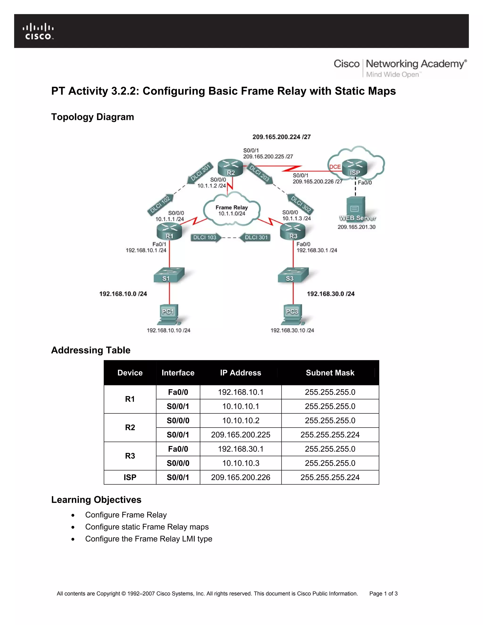
PT Activity 3.2.2: Configuring Basic Frame Relay with Static Maps
Topology Diagram
Addressing Table
Device Interface IP Address Subnet Mask
Fa0/0 192.168.10.1 255.255.255.0
R1
S0/0/1 10.10.10.1 255.255.255.0
S0/0/0 10.10.10.2 255.255.255.0
R2
S0/0/1 209.165.200.225 255.255.255.224
Fa0/0 192.168.30.1 255.255.255.0
R3
S0/0/0 10.10.10.3 255.255.255.0
ISP S0/0/1 209.165.200.226 255.255.255.224
Learning Objectives
• Configure Frame Relay
• Configure static Frame Relay maps
• Configure the Frame Relay LMI type
All contents are Copyright © 1992–2007 Cisco Systems, Inc. All rights reserved. This document is Cisco Public Information. Page 1 of 3
CCNA Exploration
Accessing the WAN: Frame Relay PT Activity 3.2.2: Configuring Basic Frame Relay with Static Maps
All contents are Copyright © 1992–2007 Cisco Systems, Inc. All rights reserved. This document is Cisco Public Information. Page 2 of 3
Introduction
In this activity, you will configure Frame Relay on the serial 0/0/0 interfaces of routers R1, R2, and R3.
You will also configure two static Frame Relay maps on each router to reach the other two routers.
Although the LMI type is autosensed on the routers, you will statically assign the type by manually
configuring the LMI.
Routers R1, R2, and R3 have been preconfigured with hostnames and IP addresses on all interfaces.
The Fast Ethernet interfaces on routers R1 and R3 are active, and the S0/0/1 interface of R2 is active.
Task 1: Configure Frame Relay
Step 1. Configure Frame Relay encapsulation on the serial 0/0/0 interface of R1.
R1(config)#interface serial0/0/0
R1(config-if)#encapsulation frame-relay
R1(config-if)#no shutdown
Step 2. Configure Frame Relay encapsulation on the serial 0/0/0 interfaces of R2 and R3.
Step 3. Test connectivity.
From the command line on PC1, verify connectivity to the PC3 host, located at 192.168.30.10, using the
ping command.
The ping from PC1 to PC3 should fail since the R1 router does not know where the 192.168.30.0 network
is. R1 must be configured with a Frame Relay map so that it can find the next hop destination to reach
that network.
Step 4. Check results.
Your completion percentage should be 40%. If not, click Check Results to see which required
components are not yet completed.
Task 2: Configure Static Frame Relay Maps
Note: Packet Tracer does not grade your map statements. However, you must still configure the
commands.
Step 1. Configure static maps on R1, R2, and R3.
Each router requires two static maps to reach the other routers. The DLCIs to reach these routers are as
follows:
Router R1:
• To reach router R2, use DLCI 102 located at IP address 10.10.10.2.
• To reach router R3, use DLCI 103 located at IP address 10.10.10.3.
Router R2:
• To reach router R1, use DLCI 201 located at IP address 10.10.10.1.
• To reach router R3, use DLCI 203 located at IP address 10.10.10.3.
Router R3:
• To reach router R1, use DLCI 301 located at IP address 10.10.10.1.
• To reach router R3, use DLCI 302 located at IP address 10.10.10.2.
CCNA Exploration
Accessing the WAN: Frame Relay PT Activity 3.2.2: Configuring Basic Frame Relay with Static Maps
All contents are Copyright © 1992–2007 Cisco Systems, Inc. All rights reserved. This document is Cisco Public Information. Page 3 of 3
The routers must also support RIP; therefore the broadcast keyword is required.
On router R1, configure the static Frame Relay maps as follows:
R1(config-if)#frame-relay map ip 10.10.10.2 102 broadcast
R1(config-if)#frame-relay map ip 10.10.10.3 103 broadcast
Configure routers R2 and R3 using the previously provided information.
Step 2. Check results.
Your completion percentage should be 80%. If not, click Check Results to see which required
components are not yet completed.
Task 3: Configure the Frame Relay LMI Type
The Frame Relay cloud contains switches that are using ANSI as the LMI type. Therefore, all the Frame
Relay links must be manually configured to use ANSI.
Step 1. Configure ANSI as the LMI type on R1, R2, and R3.
Enter the following command on the serial interface for each router.
R1(config-if)#interface s0/0/0
R1(config-if)#frame-relay lmi-type ansi
Step 2. Check results.
Your completion percentage should be 100%. If not, click Check Results to see which required
components are not yet completed.
Step 3. Test connectivity.
It is possible to complete the activity with a 100%, yet still not have connectivity. PC1 and PC3 should
now be able to successfully ping each other and the web server. If not, make sure that you entered all the
commands exactly as specified in the previous steps.

Frame relay

  • 1.
    PT Activity 3.2.2:Configuring Basic Frame Relay with Static Maps Topology Diagram Addressing Table Device Interface IP Address Subnet Mask Fa0/0 192.168.10.1 255.255.255.0 R1 S0/0/1 10.10.10.1 255.255.255.0 S0/0/0 10.10.10.2 255.255.255.0 R2 S0/0/1 209.165.200.225 255.255.255.224 Fa0/0 192.168.30.1 255.255.255.0 R3 S0/0/0 10.10.10.3 255.255.255.0 ISP S0/0/1 209.165.200.226 255.255.255.224 Learning Objectives • Configure Frame Relay • Configure static Frame Relay maps • Configure the Frame Relay LMI type All contents are Copyright © 1992–2007 Cisco Systems, Inc. All rights reserved. This document is Cisco Public Information. Page 1 of 3
  • 2.
    CCNA Exploration Accessing theWAN: Frame Relay PT Activity 3.2.2: Configuring Basic Frame Relay with Static Maps All contents are Copyright © 1992–2007 Cisco Systems, Inc. All rights reserved. This document is Cisco Public Information. Page 2 of 3 Introduction In this activity, you will configure Frame Relay on the serial 0/0/0 interfaces of routers R1, R2, and R3. You will also configure two static Frame Relay maps on each router to reach the other two routers. Although the LMI type is autosensed on the routers, you will statically assign the type by manually configuring the LMI. Routers R1, R2, and R3 have been preconfigured with hostnames and IP addresses on all interfaces. The Fast Ethernet interfaces on routers R1 and R3 are active, and the S0/0/1 interface of R2 is active. Task 1: Configure Frame Relay Step 1. Configure Frame Relay encapsulation on the serial 0/0/0 interface of R1. R1(config)#interface serial0/0/0 R1(config-if)#encapsulation frame-relay R1(config-if)#no shutdown Step 2. Configure Frame Relay encapsulation on the serial 0/0/0 interfaces of R2 and R3. Step 3. Test connectivity. From the command line on PC1, verify connectivity to the PC3 host, located at 192.168.30.10, using the ping command. The ping from PC1 to PC3 should fail since the R1 router does not know where the 192.168.30.0 network is. R1 must be configured with a Frame Relay map so that it can find the next hop destination to reach that network. Step 4. Check results. Your completion percentage should be 40%. If not, click Check Results to see which required components are not yet completed. Task 2: Configure Static Frame Relay Maps Note: Packet Tracer does not grade your map statements. However, you must still configure the commands. Step 1. Configure static maps on R1, R2, and R3. Each router requires two static maps to reach the other routers. The DLCIs to reach these routers are as follows: Router R1: • To reach router R2, use DLCI 102 located at IP address 10.10.10.2. • To reach router R3, use DLCI 103 located at IP address 10.10.10.3. Router R2: • To reach router R1, use DLCI 201 located at IP address 10.10.10.1. • To reach router R3, use DLCI 203 located at IP address 10.10.10.3. Router R3: • To reach router R1, use DLCI 301 located at IP address 10.10.10.1. • To reach router R3, use DLCI 302 located at IP address 10.10.10.2.
  • 3.
    CCNA Exploration Accessing theWAN: Frame Relay PT Activity 3.2.2: Configuring Basic Frame Relay with Static Maps All contents are Copyright © 1992–2007 Cisco Systems, Inc. All rights reserved. This document is Cisco Public Information. Page 3 of 3 The routers must also support RIP; therefore the broadcast keyword is required. On router R1, configure the static Frame Relay maps as follows: R1(config-if)#frame-relay map ip 10.10.10.2 102 broadcast R1(config-if)#frame-relay map ip 10.10.10.3 103 broadcast Configure routers R2 and R3 using the previously provided information. Step 2. Check results. Your completion percentage should be 80%. If not, click Check Results to see which required components are not yet completed. Task 3: Configure the Frame Relay LMI Type The Frame Relay cloud contains switches that are using ANSI as the LMI type. Therefore, all the Frame Relay links must be manually configured to use ANSI. Step 1. Configure ANSI as the LMI type on R1, R2, and R3. Enter the following command on the serial interface for each router. R1(config-if)#interface s0/0/0 R1(config-if)#frame-relay lmi-type ansi Step 2. Check results. Your completion percentage should be 100%. If not, click Check Results to see which required components are not yet completed. Step 3. Test connectivity. It is possible to complete the activity with a 100%, yet still not have connectivity. PC1 and PC3 should now be able to successfully ping each other and the web server. If not, make sure that you entered all the commands exactly as specified in the previous steps.