Forced Air Zone Control Presentation
•Download as PPT, PDF•
1 like•3,431 views

This is a presentation about forced air zone control we presented at the 2008 RSES National Convention in Indianapolis.

Recommended
More Related Content
What's hot
What's hot (20)
Viewers also liked
Viewers also liked (18)
Similar to Forced Air Zone Control Presentation
Similar to Forced Air Zone Control Presentation (20)
Recently uploaded
Recently uploaded (20)
Forced Air Zone Control Presentation
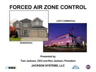
- 1. FORCED AIR ZONE CONTROL Presented by Tom Jackson, CEO and Ron Jackson, President JACKSON SYSTEMS, LLC RESIDENTIAL LIGHT COMMERCIAL
- 2. BRIEF HISTORY & FACTS The first forced air zone control system was brought to fruition over 44 years ago. Today, there are over a dozen major manufacturers of forced air zoning systems and the list keeps growing. Forced air zone control represents a Hundred-Million dollar industry. In 2007, zone control systems for residential and light commercial applications exceeded 350,000 systems. Forced air zoning is no longer a niche market but plays a major part in energy conservation and improved comfort in the home and workplace. Over 67% of US homeowners are uncomfortable in their homes. Zone control can solve the problem.
- 4. BASIC PRINCIPLE OF OPERATION The basic principle of operation for a zone control system is to allow a single HVAC system to be controlled by multiple thermostats strategically placed in areas called zones. The conditioned air entering each zone is controlled by a zone damper located in a main supply trunk line or multiple dampers located in branch runs serving the zone. The operation of the zone thermostats and dampers is controlled by a zone panel which provides the logic to energize the HVAC system in the proper mode of operation as well as controlling the zone damper positions based on each zone thermostat’s demand for heating, cooling or ventilation.
- 6. TYPES OF ZONING SYSTEMS ELECTRONIC: A typical electronic zone control system utilizes UL Class II, 24 Volts AC to provide power for the zone panel, zone thermostats, and electro-mechanical zone dampers. ZONE THERMOSTAT ZONE THERMOSTAT ELECTRO-MECHANICAL ZONE DAMPER ELECTRO-MECHANICAL ZONE DAMPER LOGIC PANEL
- 7. ELECTRO-PNEUMATIC: A typical electro-pneumatic zone control system utilizes UL Class II, 24 Volts AC to provide power for the zone panel, zone thermostats, and an air pump that creates both vacuum and pressure for air actuated dampers. TYPES OF ZONING SYSTEMS ZONE THERMOSTAT ZONE THERMOSTAT LOGIC PANEL AIR PUMP AIR ACTUATED DAMPER AIR ACTUATED DAMPER
- 11. ELECTRO-MECHANICAL TWO-POSITION Electro-mechanical two-position dampers are widely used for forced air zone control applications. Both rectangular and round dampers are available in a wide range of sizes to fit most standard trunk and branch duct configurations. Two-position dampers are either fully open or fully closed. Most have a mechanical minimum position adjustment to allow a percentage of air flow (leakage) when in the closed position. Rectangular dampers slide into the duct work and are available in side mount (actuator on the vertical plane) and bottom mount (actuator on the horizontal plane) to accommodate for restrictions such as ceiling joists. Damper actuators are available in 2-wire (Spring Open/Power Closed) or 3-wire (Power Open/Power Closed) models. A typical actuator motor is 24 Volts AC but the VA rating (the amount of power required to drive the motor) may vary within a range of 2VA to 10VA. This becomes an important factor when selecting zone control dampers as the total system VA must not exceed the transformer VA rating. TYPES OF ZONE DAMPERS
- 12. 2-POSITION ZONE DAMPERS TYPICAL 2-WIRE RECTANGULAR SIDE MOUNT ACTUATOR AND SPRING RETURN MECHANISM DAMPER BLADES MOUNTING FLANGE MINIMUM POSITION ADJUSTMENT SCREW MOUNTING DIRECTION
- 13. 2-POSITION ZONE DAMPERS TYPICAL 2-WIRE RECTANGULAR BOTTOM MOUNT ACTUATOR AND SPRING RETURN MECHANISM DAMPER BLADES MOUNTING FLANGE MINIMUM POSITION ADJUSTMENT SCREW MOUNTING DIRECTION FRONT VIEW
- 14. 2-POSITION ZONE DAMPERS TYPICAL 2- WIRE ROUND ACTUATOR AND SPRING RETURN MECHANISM DAMPER BLADE MINIMUM POSITION ADJUSTMENT SCREW
- 15. 2-POSITION ZONE DAMPERS TYPICAL 3-WIRE RECTANGULAR SIDE MOUNT ACTUATOR MINIMUM POSITION ADJUSTMENT SCREW DAMPER BLADES MOUNTING DIRECTION
- 16. 2-POSITION ZONE DAMPERS TYPICAL 3- WIRE ROUND MINIMUM POSITION ADJUSTMENT SCREW DAMPER BLADE ACTUATOR
- 17. 2-POSITION ZONE DAMPERS TYPICAL 3- WIRE RETROFIT DAMPER ACTUATOR DAMPER BLADE EXISTING DUCT WORK RETROFIT DAMPER
- 18. PNEUMATIC (AIR ACTUATED) Pneumatic dampers operate on either air pressure or vacuum provided by an air pump as part of the zone control system. There are two basic types of pneumatic air dampers. BLADDER TYPE A rubber bladder inside a damper shell or duct work retracts when a vacuum is applied allowing air to flow through the duct and inflates when pressure is applied to restrict air flow. DIAPHRAGM TYPE A diaphragm (air actuator) is incorporated with mechanical linkage to move a damper blade when either a vacuum or pressure is applied. TYPES OF ZONE DAMPERS
- 20. TYPICAL BAROMETRIC BYPASS DAMPER ARRANGEMENT BASIC SYSTEM COMPONENTS
- 21. TYPICAL BAROMETRIC BYPASS DAMPERS BASIC SYSTEM COMPONENTS ROUND RECTANGULAR
- 23. TYPICAL ELECTRONIC BYPASS DAMPER ARRANGEMENT BASIC SYSTEM COMPONENTS
- 24. TYPICAL ELECTRONIC BYPASS DAMPERS BASIC SYSTEM COMPONENTS ROUND RECTANGULAR
- 28. There are numerous control logic methods used in forced air zone control and many logic panels are designed to provide a selection of control algorithms to chose from based on the specific zoning application. COOLING PRIORITY Cooling Priority logic is designed to provide cooling first over heating. This means that if one zone calls for heating and another zone calls for cooling, cooling wins. After the cooling call is satisfied, the system will changeover to heating. HEATING PRIORITY Heating Priority logic is designed to provide heating first over cooling. If a zone calls for cooling and another zone calls for heating, heating wins. After the heating call is satisfied, the system will changeover to cooling. CONTROL LOGIC
- 29. FIRST CALL PRIORITY First Call Priority logic is designed to allow the equipment to energize in the mode of operation that matches the first zone thermostat to call. If a zone calls for heating and shortly thereafter another zone calls for cooling, heating will receive priority. Once the heating call is satisfied, the system will changeover to the cooling mode. MAJORITY WINS Majority Wins logic looks at the difference in the number of heating calls versus cooling calls. Whichever is greater receives priority. If there is a tie, most systems prioritize cooling. CONTROL LOGIC
- 34. BYPASS DAMPER SIZING CHART COOLING TONNAGE BYPASS DAMPER SIZE 2.5 8” 3 10” 4 - 5 12” 7.5 14” 10 16” 12.5 18” 15 20” SYSTEM DESIGN CONSIDERATIONS Sizing is based on bypassing 75% of the total system CFM
- 35. PUTTING IT ALL TOGETHER ZONE CONTROL SYSTEM INFORMATION CHART NUMBER OF ZONES: ________ TYPE OF EQUIPMENT: [ ] HEAT/COOL [ ] HEAT PUMP [ ] DUAL FUEL [ ] SPLIT [ ] RTU STAGES OF COOLING ______ COOLING TONNAGE ______ STAGES OF HEATING _____ TYPE OF THERMOSTATS: [ ] NON-PROGRAMMABLE [ ] PROGRAMMABLE TYPE OF DAMPERS: [ ] ROUND [ ] RECTANGULAR [ ] RETROFIT [ ] 2-WIRE [ ] 3-WIRE TRANSFORMER VA REQUIREMENT: _______VA BYPASS DAMPER SIZE: ___________