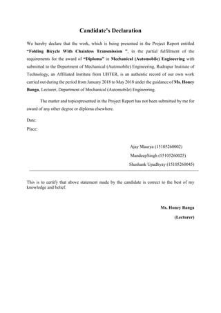
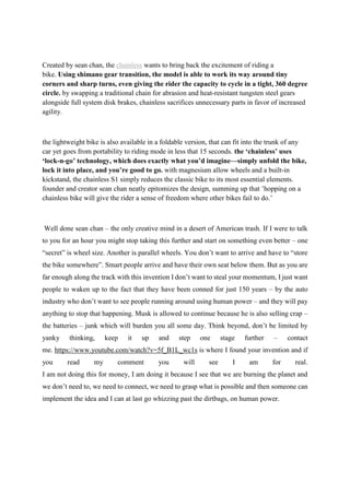
![Saddle of Bicycle
A bicycle saddle, often called a seat,[1]
is one of three contact points on an upright bicycle,
the others being the pedals and the handlebars. (A bicycle seat in the specific sense also
supports the back.) The bicycle saddle has been known as such since the bicycle evolved
from the draisine, a forerunner of the bicycle.[2][3]
It performs a similar role as a horse's
saddle, not bearing all the weight of the rider as the other contact points also take some of the
load.
A bicycle saddle is commonly attached to the seatpost and the height of the saddle can
usually be adjusted by the seatpost telescoping in and out of the seat tube.
Seat or saddle, which is it?
here are a number of misconceptions about the saddle. The first is calling or thinking of it as
a seat. A seat is designed to bear your entire weight, while a saddle is something that carries
you, but not all of your weight.
Measure the horizontal distance between the nose of the seat and the handlebars.](https://image.slidesharecdn.com/foldingcyclewithchainlesstransmission-180427180310/85/Folding-cycle-with-chainless-transmission-28-320.jpg)
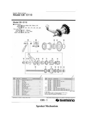


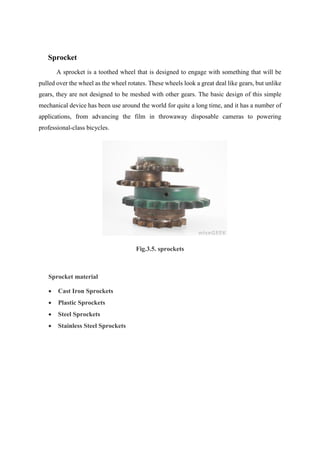
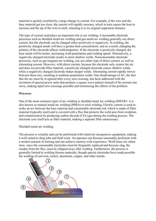
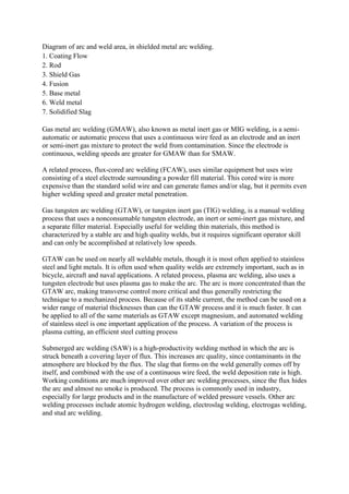
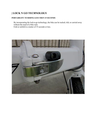
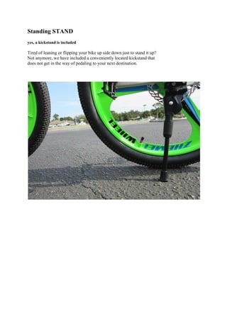
This document is a project report submitted by three students - Ajay Kumar Maurya, Mandeep Singh, and Shashank Upadhyay - for their diploma in mechanical engineering. The report describes their project on designing a "Folding Bicycle With Chainless Transmission". The bicycle uses tungsten steel gears instead of a chain for its transmission. It can fold up compactly and uses a "lock-n-go" mechanism for easy folding and unfolding. The report includes sections on the bicycle's sprocket, chassis, welding process, standing stand, frame, and other components. It evaluates the advantages and disadvantages of the chainless design.


![Internal Combustion Engine [Gasoline/Petrol] presentation](https://cdn.slidesharecdn.com/ss_thumbnails/powerplantpresentation-170130052239-thumbnail.jpg?width=640&height=640&fit=bounds)


