TechTAC® CFD Report Summary: A Comparison of Two Types of Tubing Anchor Catchers
Fm ppt
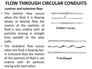
1. FLOW THROUGH CIRCULAR CONDUITS
Laminar and turbulent flow
• The laminar flow occurs
when the fluid it is flowing
slowly. In laminar flow the
motion of the particles of
fluid is very orderly with all
particles moving in straight
lines parallel to the pipe
walls.
• The turbulent flow occurs
when the fluid is flowing fast.
In turbulent flow the motion
of the particles of fluid is not
orderly with all particles
mixing with each other.
2. Flow through circular pipes – Hagen poiseuille’s equation:
Average Velocity
Loss of pressure head
this is called HAGEN-POISEUILLE FORMULA
Rdx
dp
u
2
8
1
fh
gD
Lu
g
PP
2
21 32
3. DERIVATION OF DARCY – WESIBACH EQUATION
Loss of head for flow through pipes
for laminar flow, for turbulent flow
Darcy – Weisbach formula
gD
fLV
hf
2
4 2
Re
16
f 25.0
Re
0791.0
f
4. DIFFERENT LOSSES THROUGH PIPE CARRYING THE FLUID:
MAJOR LOSS: The major loss is because of friction.
MINOR LOSSES: The minor loses are due to the
following aspects.
a) Sudden enlargement of pipe
b) Sudden contraction of pipe
c) Bend in pipe
d) An obstruction in pipe
e) Pipe fittings
5. FRICTION FACTOR & MOODY DIAGRAM:
The Moody chart or Moody diagram is a graph in non-
dimensional form that relates the Darcy-Weisbach
friction factor, Reynolds number and relative
roughness for fully developed flow in a circular pipe. It
can be used for working out pressure drop or flow
rate down such a pipe.
• Developed to provide the friction factor for
turbulent flow for various values of Relative
roughness and Reynold’s number
• Curves generated by experimental data.
6. Reynold's number and relation of friction factor (f) with Reynold number
Moody’s diagram is plotted between various values of friction factor (f),
Reynolds number (Re) and relative roughness for any turbulent flow
problem the values of friction factor(f) can be determined from moody’s
diagram, if R/K and Re of flow are known.
7. COMMERCIAL PIPES MINOR LOSSES
The loss of head due to friction is known as major loss
whiles the loss of energy due to change of velocity of the
flowing fluid in magnitude &direction is called minor loss
of energy.
The minor loses are due to the following aspects.
1. Loss of head due to sudden enlargement of pipe
2. Loss of head due to sudden contraction of pipe
3. Loss of head at the entrance to a pipe
4. Loss of head at the exit of a pipe
5. Loss of head due to Bend in pipe
6. Loss of head due to an obstruction in pipe
7. Loss of head due to Pipe fittings
8. Loss of head due to sudden enlargement of pipe:
Fig shows a liquid flowing through a pipe which has sudden
enlargement. Due to sudden enlargement, the flow is decelerated
abruptly and eddies are developed resulting in loss of energy .Consider
two sections as 1-1 and 2-2.
g
VV
he
2
2
21
9. Loss of head due to sudden contraction of pipe:
Due to sudden contraction, the streamlines converge to a minimum
cross-section called the venacontracta and then expand to fill the
downstream pipe.
g
VV
h c
c
2
2
2
10. Loss of head at entrance and exit of pipe:
This type is similar to the loss due to sudden contraction, because when
a fluid entering a pipe from a large reservoir some losses of energy
occur at the entrance of a pipe due to sudden change of area of flowing
fluid.
The outlet end of a pipe carrying liquid may be either left free or it may
be connected to a large reservoir.
g
V
hi
2
5.0
2
g
V
ho
2
2
11. Loss of head Due to bend and obstruction in pipe:
•Due to Bend:
k → depends on total angle of bend or radius of curvature of bend.
•The loss of energy due to an obstruction in the pipe takes place on
account of the reduction in the cross sectional area of the pipe by the
presence of obstruction which is followed by an abrupt enlargement of
the stream beyond the obstruction.
g
kV
hb
2
2
22
1
2
aAC
A
g
V
h
c
obs
12. Loss of head various pipe fittings and due to gradual
contraction (or) enlargement :
•Due to various pipe fittings
•When a gradual contraction or enlargement is provided in the pipe, the
loss of energy can be considerably reduced because the velocity of
liquid is gradually increased or decreased and hence eddies one
eliminated.
k → depends on angle of convergence or divergence
g
kV
hv
2
2
g
VVk
hc
2
2
21
13. Flow through Pipes in series or compound pipe:
•Due to various pipe fittings
•When a gradual contraction or enlargement is provided in the pipe, the
loss of energy can be considerably reduced because the velocity of
liquid is gradually increased or decreased and hence eddies one
eliminated.
k → depends on angle of convergence or divergence
g
kV
hv
2
2
g
VVk
hc
2
2
21
14. Flow through Pipes in series or compound pipe:
It is defined as the pipes of different diameters and lengths are
connected with one another to form a single pipeline.
The total loss of head through the entire system is sum of the losses in
all individual pipes.
15. Flow through Pipes in parallel:
When pipes of different diameters are joined ,as shown in figure ,the
pipes are said to be in parallel. For pipes in parallel, rate of flow in main
pipe is equal to sun of rate of flow through branch pipes.
The total loss of energy in each of the pipe will be same. Therefore,
Loss of head for branch pipe 1 = Loss of head for branch pipe 2
16. Hydraulic and energy gradient:
Hydraulic gradient line: HGL
The sum of potential head and pr head at any point is piezometric
head. If a Line is drawn joining the piezometric levels at various points,
the line is “HGL”.
Total energy line (TEL) (EGL):
When a fluid flows along the pipe, there is loss of head (energy) and
total energy decreases in the ‘direction’ of flow. If total energy at various
points along the axis of the pipe is plotted and joined by a line, the line
is Energy gradient line (EGL).
17. BOUNDARY LAYER CONCEPTS
Introduction:
•The boundary layer is a thin layer adjacent to the solid surface in which the
viscous effects are important. Although the thickness of the boundary layer is
very thin, one cannot neglect it. Therefore it is important to analyze the flow
within the boundary layer in details. The velocity close to the solid surface will
be same as the velocity of solid due to no-slip boundary condition. The velocity
away from the surface will be higher and therefore, there exists a velocity
gradient. The velocity gradient in a direction normal to the surface is large
compared to stream wise direction.
•To describe the concept of boundary layer, consider flow over a thin, smooth flat
plate as shown in figure. The fluid just before encountering with the plate is having a
uniform velocity.The velocity of fluid increases from zero velocity on the stationary
boundary to free – stream velocity (U) of the fluid in the direction normal to the
boundary. This variation of velocity from zero to free – stream velocity in the direction
normal to the boundary takes place in a narrow region in the vicinity of solid boundary
layer. The theory dealing with boundary layer flows is called boundary layer theory.
18. BOUNDARY LAYER CONCEPTS (contd.)
The flow of fluid may be divided into two regions:
1. A very thin layer of the fluid called the boundary layer in the
immediate
neighborhood of solid boundary
Velocity gradient exists
2.Fluid outside the boundary layer
Velocity = free stream velocity
no variation of velocity & hence
19. BOUNDARY LAYER CONCEPTS (contd.)
The boundary layer thickness is defined as the distance away from the solid
surface, where local velocity is 99% of the free stream velocity (i.e. =0.99 )
At the initial stage, near the surface of the leading edge of the plate, the
thickness of boundary layer is small and the flow in the boundary layer is
laminar though the main stream flow is turbulent. So the layer is said to be
LAMINAR BOUNDARY LAYER.
Laminar boundary layer: The flow close to the leading edge of the plate is
always laminar, in which the flow remains in orderly manner. The orderly
motion of the fluid particles remain until the Reynolds number attains a critical
value. Then the motion of the fluid particles become unstable and a small
disturbance in the flow gets amplified. The critical Reynolds number for flow
over a smooth flat plate up to which the flow is laminar is Re=500000
U
20. CLASSIFICATION OF BOUNDARY LAYER THICKNESS:
1. Displacement Thickness (δ*):
2. Momentum Thickness (θ):
3. ENERGY THICKNESS ( ):e