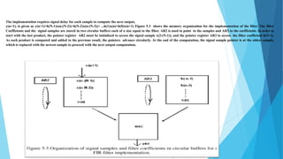
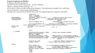
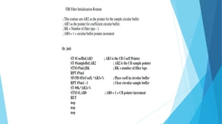
FIR Filter
Implementation
An overview of Finite Impulse Response (FIR) Filters
Introduction to FIR Filters
 FIR filters are a type of digital filter commonly used in signal processing.
The implementation requires signal delay for each sample to compute the next output,
y(n+1), is given as y(n+1)=h(N-1)x(n-(N-2))+h(N-2)x(n-(N-3))+ ...h(1)x(n)+h(0)x(n+1) Figure 5.3 shows the memory organization for the implementation of the filter. The filter
Coefficients and the signal samples are stored in two circular buffers each of a size equal to the filter. AR2 is used to point to the samples and AR3 to the coefficients. In order to
start with the last product, the pointer register AR2 must be initialized to access the signal sample x(2-(N-1)), and the pointer register AR3 to access the filter coefficient h(N-1).
As each product is computed and added to the previous result, the pointers advance circularly. At the end of the computation, the signal sample pointer is at the oldest sample,
which is replaced with the newest sample to proceed with the next output computation.
Program to implement an FIR filter:
It implements the following equation;
y(n)=h(N-1)x(n-(N-1))+h(N-2)x(n-(N-2))+ ...h(1)x(n-1)+h(0)x(n)
Where N = Number of filter coefficients = 16.
h(N-1), h(N-2),...h(0) etc are filter coefficients (q15numbers) . The coefficients are available in file: coeff_fir.dat.
x(n-(N-1)),x(n-(N-2),...x(n) are signal samples(integers).
The input x(n) is received from the data file: data_in.dat. The computed output y(n) is placed in a data buffer.
FIR Filter Routine
; Enter with A=the current sample x(n)-an integer, AR2 pointing to the location for the
current sample x(n),andAR3pointingtotheq15coefficienth(N-1). Exit with A = y(n) as
q15 number.

FIR Filter Implementation power point presentation

  • 1.
    FIR Filter Implementation An overviewof Finite Impulse Response (FIR) Filters
  • 2.
    Introduction to FIRFilters  FIR filters are a type of digital filter commonly used in signal processing.
  • 3.
    The implementation requiressignal delay for each sample to compute the next output, y(n+1), is given as y(n+1)=h(N-1)x(n-(N-2))+h(N-2)x(n-(N-3))+ ...h(1)x(n)+h(0)x(n+1) Figure 5.3 shows the memory organization for the implementation of the filter. The filter Coefficients and the signal samples are stored in two circular buffers each of a size equal to the filter. AR2 is used to point to the samples and AR3 to the coefficients. In order to start with the last product, the pointer register AR2 must be initialized to access the signal sample x(2-(N-1)), and the pointer register AR3 to access the filter coefficient h(N-1). As each product is computed and added to the previous result, the pointers advance circularly. At the end of the computation, the signal sample pointer is at the oldest sample, which is replaced with the newest sample to proceed with the next output computation.
  • 4.
    Program to implementan FIR filter: It implements the following equation; y(n)=h(N-1)x(n-(N-1))+h(N-2)x(n-(N-2))+ ...h(1)x(n-1)+h(0)x(n) Where N = Number of filter coefficients = 16. h(N-1), h(N-2),...h(0) etc are filter coefficients (q15numbers) . The coefficients are available in file: coeff_fir.dat. x(n-(N-1)),x(n-(N-2),...x(n) are signal samples(integers). The input x(n) is received from the data file: data_in.dat. The computed output y(n) is placed in a data buffer.
  • 6.
    FIR Filter Routine ;Enter with A=the current sample x(n)-an integer, AR2 pointing to the location for the current sample x(n),andAR3pointingtotheq15coefficienth(N-1). Exit with A = y(n) as q15 number.