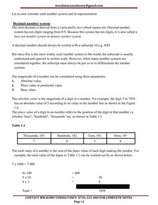
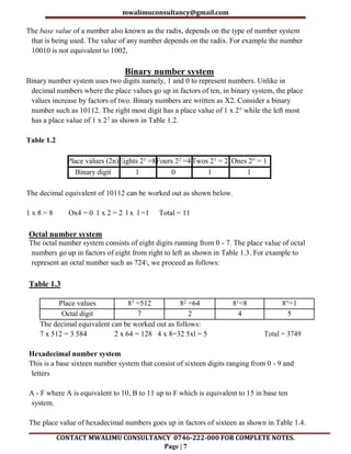
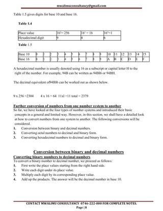
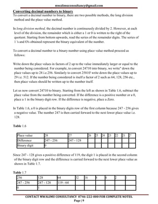
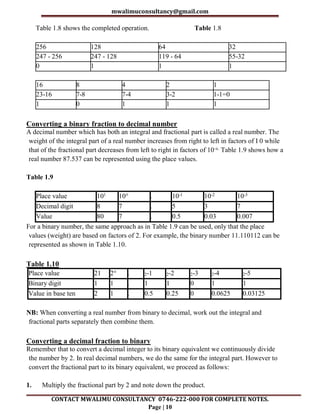
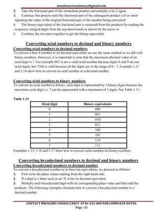
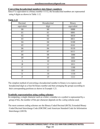
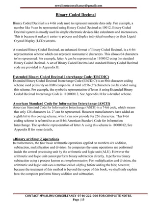
COMPUTER STUDIES NOTES
FORM 3 SIMPLIFIED VERSION
QUICK REVISION NOTES
An Updated Well-Organized Detailed Revision Notes for
the Current Form 3 Syllabus.
THIS IS A FREE SAMPLE OF THE
ORIGINAL NOTES
CONTACT US FOR FULL VERSION OF THE NOTES
Mr Isaboke 0746 222 000
MWALIMU CONSULTANCY
SERIES 1
mwalimuconsultancy@gmail.com
CONTACT MWALIMU CONSULTANCY 0746-222-000 FOR COMPLETE NOTES.
Page | 2
Copyright ©Mwalimu
All rights reserved. This book or any portion thereof may not be reproduced or used in any
manner whatsoever without the express written permission of the publisher except for the
use of brief quotations in a book review.
Printed in Kenya
00100
Nairobi
0746-222-000
mwalimuconsultancy@gmail.com
Mwalimu Consultancy Ltd.
mwalimuconsultancy@gmail.com
CONTACT MWALIMU CONSULTANCY 0746-222-000 FOR COMPLETE NOTES.
Page | 3
DATA REPRESENTATION IN A
COMPUTER
Chapter outline
1.1 Introduction
1.2 Concepts of data representation in digital computers
1.3 Bits, bytes, nibble and word
1.4 Types of data representation
1.5 Binary arithmetic operations
Introduction
In Book 1 of this series, we learnt that computers are classified according to functionality,
physical size and purpose. We saw that when classified according to functionality, computers
can be analog, digital or hybrid. Digital computers process data that is in discrete form while
analog computers process data that is continuous in nature. Hybrid computers, on the other
hand can process both discrete and continuous data.
In digital computers, the user input is first converted and transmitted as electrical pulses that
can be represented by two distinct digits' l' and '0' before processing. These two digits are
referred to as binary digits or in short bits.
Although two graphs can look different in their appearance, they may repeat themselves at
equal time intervals. Electronic signals or waveforms of this nature are said to be periodic.
Generally, a periodic wave representing a signal can be described using the following
parameters.
1. Amplitude (A)
2. Frequency (f)
3. Periodic time (T)
Amplitude (A): Amplitude is the maximum value a wave can attain. For example, the
amplitude of waves in Figure 1.1 is 1.
Frequency (f): Frequency of a wave is the number of cycles made by the wave in one second.
It is measured in units called hertz (Hz). 1Hz is equivalent to 1 cycle/second.
Periodic time (T): The time taken by a signal to complete one cycle is called periodic time.
Periodic time, T, is given by the formula T = 1/f where f is the frequency of the wave.
mwalimuconsultancy@gmail.com
CONTACT MWALIMU CONSULTANCY 0746-222-000 FOR COMPLETE NOTES.
Page | 4
When a digital signal is to be sent over analog telephone lines e.g. e-mail, it has to be
converted to analog signal. This is done by connecting a device called a modem to the digital
computer. This process of converting a digital signal to an analog signal is known as
modulation. On the receiving end, the incoming analog signal is converted back to digital
form in a process known as demodulation.
Concepts of data representation in digital computers
Since digital computers are the most widely used, this book seeks to explain in details how
data is represented in digital form.
Data and instructions cannot be entered and processed directly into computers using human
language. Any type of data be it numbers, letters, special symbols, sound or pictures must
first be converted into machine readable form i.e. binary form. Due to this reason, it is
important to understand how a computer together with its peripheral devices handle data in
its electronic circuits, on magnetic media arid in optical devices.
Data representation in electronic circuits
Electronics components, such as the microprocessor, are made up of millions of electronic
circuits. The availability of a high voltage (on) in these circuits is interpreted as 'I' while a
low voltage (off) is interpreted as a '0'. This concept can be compared to switching on and off
of an electric circuit. (Figure 1.3). When the switch is closed, (Figure 1.3 (a)), the high
voltage in the circuit causes the bulb to light (' l' state). On the other hand, when the switch is
open (Figure 1.3 (b)), the bulb goes off ('0' state).
Data representation on magnetic media
The presence of a magnetic field in one direction on magnetic media is interpreted as 'I', while
the field in the opposite direction is interpreted as '0'. Magnetic technology is mostly used on
storage devices which are coated with special magnetic materials such as iron oxide. Data is
written on the media by arranging the magnetic dipoles of some iron oxide particles to face
in the same direction and some others in the opposite direction. Figure 1.4 shows how data is
recorded on the surface of a magnetic disk. Note that the dipoles on the track are arranged in
groups facing opposite directions.
Data representation on optical media
In optical devices, the presence of light is interpreted as '1' while its absence is interpreted as
'0'. Optical devices use this technology to read or store data. Take an example of a CD-ROM.
If the shiny surface is placed under a powerful microscope, the surface can be observed to
have very tiny holes called pits. The areas that do not have pits are called land (Figure 1.5).
In Figure 1.5 (a) the laser beam reflects from the land which is interpreted as '1' while in
Figure 1.5 (b) the laser beam enters a 'pit' and is not reflected. This is interpreted as '0'. The
mwalimuconsultancy@gmail.com
CONTACT MWALIMU CONSULTANCY 0746-222-000 FOR COMPLETE NOTES.
Page | 5
reflected pattern of light from the rotating disk falls on a receiving photoelectric detector that
transforms the patterns into digital form.
Reason for use of binary system in computers
It has proved difficult to develop devices that can understand or process natural language
directly due to the complexity of natural languages. It is, however, possible to develop
devices that can understand binary language. Devices that read, process and output data in
digital form are used in computers and other digital devices such as calculators. Binary logic
has therefore simplified the technology needed to develop both hardware and software
systems. Other reasons for the use of binary are that digital devices are more reliable, small
in size and use less energy as compared to analog devices.
Bits, bytes, nibble and word
The terms bits, bytes, nibble and word are used widely in reference to computer memory and
data size. Let us explain each term.
Bits: A bit can be defined as binary digits that can either be 0 or 1. It is the basic unit of data or
information in digital computers.
Byte: A group of bits (often 8) used to represent a character is called a byte. A byte is
considered as the basic unit of measuring memory size in computers.
A nibble: Half a byte, which is usually a grouping of 4 bits is called a nibble.
Word: Two or more bytes make a word. The term word length is used as a measure of the
number of bits in each word. For example a word can have a length of 16 bits, 32 bits, 64 bits
etc.
Types of data representation
Computers not only process numbers, letters and special symbols but also complex types of
data such as sound and pictures. However these complex types of data take a lot of memory
and processor time when coded in binary form. This limitation necessitates the need to
develop better ways of handling long streams of binary digits. Higher number systems are
used in computing to reduce these streams of binary into manageable form. This helps to
improve the processing speed and optimise memory usage.
Number systems and their representation
As far as computers are concerned, number systems can be classified into four major
categories:
1. Decimal number system.
2. Binary number system
3. Octal number system.
4. Hexadecimal number systems.
mwalimuconsultancy@gmail.com
CONTACT MWALIMU CONSULTANCY 0746-222-000 FOR COMPLETE NOTES.
Page | 6
Let us now consider each number system and its representation.
Decimal number system
The term decimal is derived from a Latin prefix deci which means ten. Decimal number
system has ten digits ranging from 0-9. Because this system has ten digits, it is also called a
base ten number system or denary number system,
A decimal number should always be written with a subscript 10 e.g. XIO
But since this is the most widely used number system in the world, the subscript is usually
understood and ignored in written work. However, when many number systems are
considered together, the subscript must always be put so as to differentiate the number
systems.
The magnitude of a number can be considered using three parameters.
1. Absolute value.
2. Place value or positional value.
3. Base value.
The absolute value is the magnitude of a digit in a number. For example, the digit 5 in 7458
has an absolute value of 5 according to its value in the number line as shown in the Figure
1.6.
The place value of a digit in an number refers to the position of the digit in that number i.e.
whether "tens", "hundreds", "thousands" etc. as shown in Table 1.1.
Table 1.1
Thousands, 103 Hundreds, 102 Tens, 101 Ones, 10°
7 4 5 8
The total value of a number is the sum of the place value of each digit making the number. For
example, the total value of the digits in Table 1.1 can be worked out by as shown below:
7 x 1000 = 7 000
4x 100 = 400
5 x 10 = 50
8 x l = 8
Total = 7458
mwalimuconsultancy@gmail.com
CONTACT MWALIMU CONSULTANCY 0746-222-000 FOR COMPLETE NOTES.
Page | 7
The base value of a number also known as the radix, depends on the type of number system
that is being used. The value of any number depends on the radix. For example the number
10010 is not equivalent to 1002,
Binary number system
Binary number system uses two digits namely, 1 and 0 to represent numbers. Unlike in
decimal numbers where the place values go up in factors of ten, in binary system, the place
values increase by factors of two. Binary numbers are written as X2. Consider a binary
number such as 10112. The right most digit has a place value of 1 x 2° while the left most
has a place value of 1 x 23 as shown in Table 1.2.
Table 1.2
Place values (2n)Eights 23 =8Fours 22 =4Twos 21 = 2 Ones 2° = 1
Binary digit 1 0 1 1
The decimal equivalent of 10112 can be worked out as shown below.
1 x 8 = 8 Ox4 = 0 1 x 2 = 2 l x l =1 Total = 11
Octal number system
The octal number system consists of eight digits running from 0 - 7. The place value of octal
numbers go up in factors of eight from right to left as shown in Table 1.3. For example to
represent an octal number such as 724, we proceed as follows:
Table 1.3
Place values 83 =512 82 =64 81=8 8°=1
Octal digit 7 2 4 5
The decimal equivalent can be worked out as follows:
7 x 512 = 3 584 2 x 64 = 128 4 x 8=32 5xl = 5 Total = 3749
Hexadecimal number system
This is a base sixteen number system that consist of sixteen digits ranging from 0 - 9 and
letters
A - F where A is equivalent to 10, B to 11 up to F which is equivalent to 15 in base ten
system.
The place value of hexadecimal numbers goes up in factors of sixteen as shown in Table 1.4.
mwalimuconsultancy@gmail.com
CONTACT MWALIMU CONSULTANCY 0746-222-000 FOR COMPLETE NOTES.
Page | 8
Table 1.5 gives digits for base 10 and base 16.
Table 1.4
Place value 162= 256 161 = 16 16°=1
Hexadecimal digit 9 4 6
Table 1.5
Base 10 0 1 2 3 4 5 6 7 8 9 10 11 12 13 14 15
Base 16 0 1 2 3 4 5 6 7 8 9 A B C D E F
A hexadecimal number is usually denoted using 16 as a subscript or capital letter H to the
right of the number. For example, 94B can be written as 94BI6 or 94BH.
The decimal equivalent of94BI6 can be worked out as shown below.
9 x 256 =2304 4 x 16 = 64 11xl =11 total = 2379
Further conversion of numbers from one number system to another
So far, we have looked at the four types of number systems and introduced their basic
concepts in a general and limited way. However, in this section, we shall have a detailed look
at how to convert numbers from one system to another. The following conversions will be
considered.
1. Conversion between binary and decimal numbers.
2. Converting octal numbers to decimal and binary form.
3. Converting hexadecimal numbers to decimal and binary form.
Conversion between binary and decimal numbers
Converting binary numbers to decimal numbers
To convert a binary number to decimal number, we proceed as follows:
1. First write the place values starting from the right hand side.
2. Write each digit under its place value.
3. Multiply each digit by its corresponding place value.
4. Add up the products. The answer will be the decimal number in base 10.
mwalimuconsultancy@gmail.com
CONTACT MWALIMU CONSULTANCY 0746-222-000 FOR COMPLETE NOTES.
Page | 9
Converting decimal numbers to binary
To convert a decimal number to binary, there are two possible methods, the long division
method and the place value method.
In long division method, the decimal number is continuously divided by 2. However, at each
level of the division, the remainder which is either a 1 or 0 is written to the right of the
quotient. Starting from bottom upwards, read the series of the remainder digits. The series of
1 's and O's obtained represent the binary equivalent of the number.
To convert a decimal number to a binary number using place value method proceed as
follows:
Write down the place values in factors of 2 up to the value immediately larger or equal to the
number being considered. For example, to convert 24710 into binary, we write" down the
place values up to 28 i.e.256. Similarly to convert 25810' write down the place values up to
29 i.e. 512. If the number being considered is itself a factor of 2 such as 64, 128, 256 etc.,
then place values should be written up to the number itself.
Let us now convert 24710 to binary. Starting from the left as shown in Table 1.6, subtract the
place value from the number being converted. If the difference is a positive number or a 0,
place a 1 in the binary digit row. If the difference is negative, place a Zero.
In Table 1.6, a 0 is placed in the binary digits row of the first column because 247 - 256 gives
a negative value. The number 247 is then carried forward to the next lower place value i.e.
128.
Table 1.6
Place value 28 27 26 25 24 23 22 21 2°
Difference 247 - 256 247 - 128
Binary digit 0
Since 247 - 128 gives a positive difference of 119, the digit 1 is placed in the second column
of the binary digit row and the difference is carried forward to the next lower place value as
shown in Table 1.7.
Table 1.7
256 128 64 32 16 8 4 2 1
247 - 256 247 - 128 119 - 64
0 1
mwalimuconsultancy@gmail.com
CONTACT MWALIMU CONSULTANCY 0746-222-000 FOR COMPLETE NOTES.
Page | 10
Table 1.8 shows the completed operation. Table 1.8
256 128 64 32
247 - 256 247 - 128 119 - 64 55-32
0 1 1 1
16 8 4 2 1
23-16 7-8 7-4 3-2 1-1=0
1 0 1 1 1
Converting a binary fraction to decimal number
A decimal number which has both an integral and fractional part is called a real number. The
weight of the integral part of a real number increases from right to left in factors of I 0 while
that of the fractional part decreases from left to right in factors of 10-x. Table 1.9 shows how a
real number 87.537 can be represented using the place values.
Table 1.9
Place value 101 10° . 10-1 10-2 10-3
Decimal digit 8 7 . 5 3 7
Value 80 7 . 0.5 0.03 0.007
For a binary number, the same approach as in Table 1.9 can be used, only that the place
values (weight) are based on factors of 2. For example, the binary number 11.110112 can be
represented as shown in Table 1.10.
Table 1.10
Place value 21 2° . 2-1 2-2 2-3 2-4 2-5
Binary digit 1 1 . 1 1 0 1 1
Value in base ten 2 1 . 0.5 0.25 0 0.0625 0.03125
NB: When converting a real number from binary to decimal, work out the integral and
fractional parts separately then combine them.
Converting a decimal fraction to binary
Remember that to convert a decimal integer to its binary equivalent we continuously divide
the number by 2. In real decimal numbers, we do the same for the integral part. However to
convert the fractional part to its binary equivalent, we proceed as follows:
1. Multiply the fractional part by 2 and note down the product.
mwalimuconsultancy@gmail.com
CONTACT MWALIMU CONSULTANCY 0746-222-000 FOR COMPLETE NOTES.
Page | 11
2. Take the fractional part of the immediate product and multiply it by 2 again.
3. Continue this process until the fractional part of the subsequent product is 0 or starts
repeating the value of the original fractional part of the number being converted:
4. The binary equivalent of the fractional part is extracted from the products by reading the
respective integral digits from the top downwards as shown by the arrow in
5. Combine the two parts together to get the binary equivalent.
Converting octal numbers to decimal and binary numbers
Converting octal numbers to decimal numbers
To convert a base 8 number to its decimal equivalent we use the same method as we did with
binary numbers. However, it is important to note that the maximum absolute value of an
octal digit is 7. For example 982 is not a valid octal number because digits 8 and 9 are not
octal digits, but 7368 is valid because all the digits are in the range of 0 - 7. Example 1.13
and 1.14 show how to convert an octal number to a decimal number.
Converting octal numbers to binary numbers
To convert an octal number to binary, each digit is represented by 3 binary digits because the
maximum octal digit i.e. 7 can be represented with a maximum of 3 digits. See Table 1.11.
Table 1.11
Octal digit Binary equivalents
0 000
1 001
2 010
3 011
4 100
5 101
6 110
7 111
Examples 1.15, 1.16 and 1.17 show how to convert octal numbers to binary numbers.
Converting hexadecimal numbers to decimal and binary numbers
Converting hexadecimal numbers to decimal number
To convert a hexadecimal number to its base ten equivalents, we proceed as follows:
1. First write the place values starting from the right hand side.
2. If a digit is a letter such as an 'A' write its decimal equivalent.
3. Multiply each hexadecimal digit with its corresponding place value and then add the
products. The following examples illustrate how to convert a hexadecimal number to a
decimal number.
mwalimuconsultancy@gmail.com
CONTACT MWALIMU CONSULTANCY 0746-222-000 FOR COMPLETE NOTES.
Page | 12
Converting hexadecimal numbers into binary numbers
Since F is equivalent to a binary number 11112, the hexadecimal numbers are represented
using 4 digits as shown in Table 1.12.
Table 1.12
Decimal. Hexadecimal Binary
equivalent digit equivalent
00 00 0000
01 01 0001
02 02 0010
03 03 0011
04 04 0100
05 05 0101
06 06 0110
07 07 0111
08 08 1000
09 09 1001
A 10 1010
B 11 1011
C 12 1100
D 13 1101
E 14 1110
F 15 1111
The simplest method of converting a hexadecimal number to binary is to express each
hexadecimal digit as a four bit binary number and then arranging the groups according to
their corresponding positions as shown in Example 1.21.
Symbolic representation using coding schemes
In computing, a single character such as a letter, a number or a symbol is represented by a
group of bits, the number of bits per character depends on the coding scheme used.
The most common coding schemes are the Binary Coded Decimal (BCD), Extended Binary
Coded Decimal Interchange Code (EBCDIC) and American Standard Code for Information
Interchange (ASCII).
mwalimuconsultancy@gmail.com
CONTACT MWALIMU CONSULTANCY 0746-222-000 FOR COMPLETE NOTES.
Page | 13
Binary Coded Decimal
Binary Coded Decimal is a 4-bit code used to represent numeric data only. For example, a
number like 9 can be represented using Binary Coded Decimal as 10012, Binary Coded
Decimal system is mostly used in simple electronic devices like calculators and microwaves.
This is because it makes it easier to process and display individual numbers on their Liquid
Crystal Display (LCD) screens.
A standard Binary Coded Decimal, an enhanced format of Binary Coded Decimal, is a 6-bit
representation scheme which can represent nonnumeric characters. This allows 64 characters
to be represented. For example, letter A can be represented as 1100012 using the standard
Binary Coded Decimal. A set of Binary Coded Decimal and standard Binary Coded Decimal
code are provided in Appendix II.
Extended Binary Coded Decimal Interchange Code (EBCDIC)
Extended Binary Coded Decimal Interchange Code (EBCDIC) is an 8bit character coding
scheme used primarily on IBM computers. A total of256 (28) characters can be coded using
this scheme. For example, the symbolic representation of letter A using Extended Binary
Coded Decimal Interchange Code is 110000012, See Appendix II for a detailed scheme.
American Standard Code for Information Interchange (ASCII)
American Standard Code for Information Interchange (ASCII) is a 7-bit code, which means
that only 128 characters i.e. 27 can be represented. However manufacturers have added an
eighth bit to this coding scheme, which can now provide for 256 characters. This 8-bit
coding scheme is referred to as an 8-bit American Standard Code for Information
Interchange. The symbolic representation of letter A using this scheme is 10000012, See
Appendix II for more details,
»Binary arithmetic operations
In mathematics, the four basic arithmetic operations applied on numbers are addition,
subtraction, multiplication and division. In computers the same operations are performed
inside the central processing unit by the arithmetic and logic unit (ALU). However the
arithmetic and logic unit cannot perform binary subtraction directly. It performs binary
subtraction using a process known as complementation. For multiplication and division, the
arithmetic and logic unit uses a method called shifting before adding the bits; however,
because the treatment of this method is beyond the scope of this book, we shall only explain
how the computer performs binary addition and subtraction.
mwalimuconsultancy@gmail.com
CONTACT MWALIMU CONSULTANCY 0746-222-000 FOR COMPLETE NOTES.
Page | 14
Representation of signed binary numbers
In computer technology there are three common ways of representing a signed binary number.
1. Prefixing an extra sign bit to a binary number.
2. Using ones complement.
3. using twos complement.
Prefixing an extra sign bit to a binary number
In decimal numbers, a signed number has a prefix "+" for a positive number e.g. +2710 and "-
" for a negative number e.g. -2710 However in binary, a negative number may be represented
by prefixing a digit 1 to the number while a positive number may be represented by prefixing
a digit O. For example, the 7-bit binary equivalent of 127 is 11111112, To indicate that it is
positive, we add an extra bit (0) to the left of the number i.e. (0) 11111112, To indicate that it
is a negative number we add an extra bit (1) i.e. (1) 11111112, The problem of using this
method is that the zero can be represented in two ways i.e. (0)00000002 and (1 )00000002,
Ones complement
. The term complement refers to a part which together with another makes up a whole. For
example in geometry two complementary angles add up to one right angle (90°). The idea of
complement is used to address the problem of signed numbers i.e., positive and negative.
In decimal numbers (0 to 9), we talk of nine's complement. For example the nines
complement of 9 is 0 that of 5 is 4 while that of 3 is 6. However, in binary numbers, the ones
complement is the bitwise NOT applied to the number. Bitwise NOT is a unary operator
(operation on only one operand) that performs logical negation on each bit. For example the
bitwise NOT of 11002 is 00112 i.e. Os are negated to Is while I's are negated to O’s.
Likewise the bitwise NOT of 00 1 0
11 0 1 is 110100102 which represents -4510' The bitwise NOT of 8-bit zero 000000002 is
111111112, Looking at the two numbers, the most significant digit shows that the number
has a sign bit "0" for "+0" and" 1" for "-0". Like in the method of using an extra sign bit, in
ones complement, there are two ways of representing a zero.
Twos complement
Twos complement, equivalent to tens complement in decimal numbers, is the most popular
way of representing negative numbers in computer systems. The advantages of using this
method are:
1. There are no two ways of representing a zero, as is the case with the other two methods.
2. Effective addition and subtraction can be done even with numbers that are represented
with a sign bit without a need for extra circuitries to examine the sign of an operand.
mwalimuconsultancy@gmail.com
CONTACT MWALIMU CONSULTANCY 0746-222-000 FOR COMPLETE NOTES.
Page | 15
The twos complement of a number is obtained by getting the ones complement then adding a
1. For example, to get the twos complement of a decimal number 4510' first convert it to
its binary equivalent then find its ones complement. Add a 1 to the ones complement i.e.
4510 = 001011012
Bitwise NOT (00101101) = 11010010
Two's complement = 110100112
Binary addition
The five possible additions in binary are:
1. 0+0=0
2. 0+12=12
3. 12+0=12
4. 12 + 12 =102 (read as 0, carry 1)
5. 12 + 12 + 12 = 112 (read as 1, carry 1)
Binary subtraction
Direct subtraction
The four possible subtractions in binary are:
1. 0-0=0
2. 12-0= 1
3. 12-12=0
4. 102 - 12 = 12 (Borrow 1 from the next most significant digit to make 0 become 102,
hence 102 -
12 = 12)
The following examples illustrate binary. Subtraction using the direct. method.
Subtraction using ones complements
The main purpose of using the ones complement in computers is to perform binary
subtractions.
For example to get the difference in 5 - 3, using the ones complement, we proceed as follows:
1. Rewrite the problem as 5 + (-3) to show that the computer performs binary subtraction
by adding the binary equivalent of 5 to the ones complement of 3.
2.Convert the absolute value of 3 into 8-bit equivalent i.e. 000000112,
3.Take the ones complement of 000000 112 i.e. 111111002 which is the binary representation
of -310'
4. Add the binary equivalent of5 to the one's complement of3 i.e.
000000101
mwalimuconsultancy@gmail.com
CONTACT MWALIMU CONSULTANCY 0746-222-000 FOR COMPLETE NOTES.
Page | 16
+ 111111000
(1)00000001
Looking at the difference of the two binary numbers, you will observe that:
1. It has a ninth bit. The ninth bit is known as an overflow bit.
2. The result show that the difference between the two numbers is 00000001. This is not
true! We know that it should be 00000010.
To address this problem in a system that uses ones complement, the overflow digit is added
back to the magnitude of the 8-bit difference. Therefore the difference becomes 00000001 +
1 = 00000010, which is the correct answer.
Subtraction using twos complements
Like in ones complement, the twos complement of a number is obtained by negating a
positive number to its negative counterpart. For example to get the difference in 5 - 3, using
the two's complement, we proceed as follows:
1. Rewrite the problem as 5 + (-3).
2. Convert the absolute value of 3 into 8-bit binary equivalent i.e. 00000011.
3. Take the ones complement of 000000 11 i.e. 11111100.
4. Add a 1 to the ones complement i.e. 11111100 to get 11111101
5. Add the binary equivalent of 5 to the twos complement of 3 i.e. 000000101
+ 111111001
(1 )000000 1 0
6. Ignoring the overflow bit, the resulting number is 00000010 which is directly read as a
binary equivalent of +2.
This is a Property of Mwalimu Consultancy Ltd. Contact Mr Isaboke
0746-222-000 for more Educational Materials.
mwalimuconsultancy@gmail.com
CONTACT MWALIMU CONSULTANCY 0746-222-000 FOR COMPLETE NOTES.
Page | 17
DATA PROCESSING
Chapter outline
2.1 Introduction
2.2 Data processing cycle
2.3 Description of errors in data processing
2.4 Data integrity
2.5 Data processing methods
2.6 Computer files
2.7 Types of computer processing files
2.8 File organisation methods
2.9 Electronic data processing modes
Introduction
Data refers to the raw facts that do not have much meaning to the user and may include
numbers, letters, symbols, sound or images. Information, on the other hand, refers to the
meaningful output obtained after processing the data.
Therefore the data processing refers to the process of transforming raw data into meaningful
output i.e. information. Data processing can be done manually using pen and paper,
mechanically using simple devices like typewriters or electronically using modem data
processing tools such as computers. Electronic data processing has become so popular that
manual and mechanical methods are being pushed to obsolescence.
Data processing cycle
Data processing cycle refers to input-process-output stages that data goes through to be
transformed into information. It is often referred to as a cycle because the output obtained
can be stored after processing and may be used in future as input. The four main stages of
data processing cycle are:
1. Data collection
2. Data input
3. Processing
4. Output
Data collection
Data collection is also referred to as data gathering or fact-finding. It involves looking for
crucial facts needed for processing.
mwalimuconsultancy@gmail.com
CONTACT MWALIMU CONSULTANCY 0746-222-000 FOR COMPLETE NOTES.
Page | 18
Methods of data collection
Some methods of data collection include interviews, use of questionnaires, observation etc. In
most cases, the data is collected after sampling. Sampling is the process of selecting
representative elements (e.g. people, organisations) from an entire group (population) of
interest. Some of the tools that help in the data collection include source documents such as
forms, data capture devices such as a digital camera etc.
Stages of data collection
The process of data collection may involve a number of stages depending on the method used.
These include:
Data creation: This is the process of putting together facts in an organised format. This may
be in form of manually prepared document or captured from the source using a data capture
device such as a bar code reader.
Data transmission: This will depend on whether data need to be transmitted via
communication media to the central office.
Data preparation: This is transcription (conversion) of data from source document to
machine-readable form. This may not be the case for all input devices. Data collected using
devices that directly capture data in digital form do not require transcription.
. Media conversion: Data may need to be converted from one medium to another e.g. from a
floppy disk to hard disk for faster input.
Input validation: Data entered into the computer is subjected to validity checks by a
computer program before being processed to reduce errors at the input.
Sorting: In case the data needs to be arranged in a predefined order, it is first sorted before
processing.
Data input
Data input refers to a process where the collected data is converted from human readable form
to machine-readable form (binary form). The conversion takes place in the input device.
Processing
This is the transformation of input data by the central processing unit (CPU) to a more
meaningful output (information). Some of the operations performed on data include
calculations, comparing values and sorting.
Output
The final activity in data processing cycle is producing the desired output also referred to as
information. The information can then be distributed to the target group or stored for future
use. Distribution is making the information available to those who need it and is sometimes
called information dissemination. This process of dissemination may involve electronic
presentation over radio or television, distribution of hard copies, broadcasting messages over
the Internet or mobile phones etc.
mwalimuconsultancy@gmail.com
CONTACT MWALIMU CONSULTANCY 0746-222-000 FOR COMPLETE NOTES.
Page | 19
Description of errors in data processing
The accuracy of computer output is very critical. As the saying goes, garbage in, garbage out
(GIGO), the accuracy of the data entered in the computer directly determines the accuracy of
the information given out.
Some of the errors that influence the accuracy of data input and information output include
transcription, computation and algorithm errors.
Transcription errors
Transcription errors occur during data entry. Such errors include misreading and transposition
errors.
Misreading errors
Incorrect reading of the source document by the user and hence entering wrong values bring
about misreading errors. For example, a user may misread a hand written figure such as 589
and type S86 instead i.e. confusing 5 for S.
Transposition errors
Transposition errors results from incorrect arrangement of characters i.e. putting characters in
the wrong order. For example, the user may enter 396 instead of369.
Transcription errors can be avoided by using modem data capture devices such as bar code
readers, optical character readers, and digital cameras etc., which enter data with minimum
user intervention.
Computational errors
Computational errors occur when an arithmetic operation does not produce the expected
results.
The most common computation errors include overflow, truncation and rounding errors.
Overflow errors
An overflow occurs if the result from a calculation is too large to be stored in the allocated
memory space. For example if a byte is represented using 8 bits, an overflow will occur if the
result of a calculation gives a 9-bit number.
Truncation errors
Truncation errors result from having real numbers that have a long fractional part that cannot
fit in the allocated memory space. The computer would truncate or cut off the extra
characters from the fractional part. For example, a number like 0.784969 can be truncated to
four digits to become 0.784. The resulting number is not rounded off.
mwalimuconsultancy@gmail.com
CONTACT MWALIMU CONSULTANCY 0746-222-000 FOR COMPLETE NOTES.
Page | 20
Rounding errors
Rounding errors results from raising or lowering a digit in a real number to the required
rounded number. For example, to round off 30 666 to one decimal place, we raise the first
digit after the decimal point if its successor is more than 5. In this case, the successor is 6
therefore 30.666 rounded up to one decimal place is 30.7. If the successor is below 5, e.g.
30.635, we round down the number to 30.6.
Algorithm or logical errors
An algorithm is a set of procedural steps followed to solve a given problem. Algorithms are
used as design tools when writing programs. Wrongly designed programs would result in a
program that runs but gives erroneous output. Such errors that result from wrong algorithm
design are referred to as algorithm or logical errors.
Data integrity
Data integrity refers to the accuracy and completeness of data entered in a computer or
received from the information system. Integrity is measured in terms of accuracy, timeliness
and relevance of data.
Accuracy
Accuracy refers to how close an approximation is to an actual value. As long as the correct
instructions and data are entered, computers produce accurate results efficiently. In numbers,
the accuracy of a real number depends on the number. For example 72.1264 is more accurate
than 72.13.
Timeliness
Timeliness of data and information is important because data and information have a time
value attached to them. If received late, information may have become meaningless to the
user. For example, information on the newspaper that is meant to invite people for a meeting
or occasion must be printed prior to the event and not later.
Relevance
Data entered into the computer must be relevant in order to get the expected output. In this
case, relevance means that the data entered must be pertinent to the processing needs at hand
and must meet the requirements of the processing cycle. The user also needs relevant
information for daily operations or decision making.
Threat to data integrity
Threats to data integrity can be minimized through the following ways:
1. Backup data preferably on external storage media.
2. Control access to data by enforcing security measures.
3. Design user interfaces that minimize chances of invalid data entry.
mwalimuconsultancy@gmail.com
CONTACT MWALIMU CONSULTANCY 0746-222-000 FOR COMPLETE NOTES.
Page | 21
4. Using error detection and correction software when transmitting data.
5. Using devices that directly capture data from the source such as bar code readers, digital
cameras, optical character readers etc.
Data processing methods.
As mentioned earlier, data can be processed manually, mechanically or electronically.
Manual data processing
In manual data processing, most tasks are done manually with a pen and a paper. For example
in a busy office, incoming tasks (input) are stacked in the "in tray". The processed tasks are
then put in the "out tray" (output). The processing of each task involves a person using the
brain in order to respond to queries. The processed information from the out tray is then
distributed to the people who need it or stored in a file cabinet.
Mechanical data processing
Manual processing is cumbersome and boring especially when processing repetitive tasks.
Mechanical devices were developed to help in automation of manual tasks. Examples of
mechanical devices include the typewriter, printing press and weaving looms. Initially, these
devices did not have any electronic intelligence.
Electronic data processing
For a long time, scientists have researched on how to develop machines or devices that would
simulate some form of human intelligence during data and information processing. This was
made possible to some extent with the development of electronic programmable devices such
as computers.
The advent of microprocessor technology has greatly enhanced data processing efficiency and
capability. Some of the microprocessor-controlled devices include computers, cellular
(mobile) phones, calculators, fuel pumps, modem television sets, washing machines etc.
Computer files
A file can be defined as a collection of related records that give a complete set of information
about a certain item or entity. A file can be stored manually in a file cabinet or electronically
in computer storage devices. Computerized storage offers a much better way of holding
information than the manual filing systems, which heavily rely on the concept of the file
cabinet. Some of the advantages of computerized filing system include:
1. Information takes up much less space than the manual filing.
2. It is much easier to update or modify information.
3. It offers faster access and retrieval of data.
4. It enhances data integrity and reduces duplication.
mwalimuconsultancy@gmail.com
CONTACT MWALIMU CONSULTANCY 0746-222-000 FOR COMPLETE NOTES.
Page | 22
Elements of a computer file
A computer file is made up of three elements namely: characters, fields and records.
Characters A character is the smallest element in a computer file and refers to a letter,
number or symbol that can be entered, stored and output by a computer. A character is made
up of a set of seven or eight bits depending on the character-coding scheme used.
Fields
A field is a single character or collection of characters that represents a single piece of data.
For example, in a student’s record, the student's admission number is an example of a field.
Records
A record is a collection of related fields that represent a single entity. For example, in a class
score sheet, details of each student in a row such as admission number, name, total marks
and position make up a record.
Logical and physical files
Computer files are classified as either logical or physical.
Logical files
A logical file is a type of file viewed in terms of what data items it contains and details of
what processing operations may be performed on the data items. It does not have
implementation specific information like field, data types, size and file type. Logical files are
discussed in system design later in the book.
Physical files
As opposed to a logical file, a physical file is one that is viewed in terms of how data is stored
on a storage media and how the processing operations are made possible. Physical files have
implementation specific details such as characters per field and data type for each field.
Physical files are discussed later in system implementation and operation in this book.
Types of computer processing files
There are numerous types of files used for storing data needed for processing, reference or
backup. The main common types of processing files include master files, transaction,
reference, backup, report and sort file.
Master file
A master file is the main file that contains relatively permanent records about particular items
or entries. For example a customer file will contain details of a customer such as customer
ID, name and contact address.
mwalimuconsultancy@gmail.com
CONTACT MWALIMU CONSULTANCY 0746-222-000 FOR COMPLETE NOTES.
Page | 23
Transaction (movement) file
A transaction file is used to hold input data during transaction processing. The file is later
used to update the master file and audit daily, weekly or monthly transactions. For example
in a busy supermarket, daily sales are recorded on a transaction file and later used to update
the stock file.
The file is also used by the management to check on the daily or periodic transactions.
Reference file
A reference file is mainly used for reference or look-up purposes. Lookup information is that
information which is stored in a separate file but is required during processing. For example,
in a point of sale terminal, the item code entered either manually or using a bar code reader
looks up the item description and price from a reference file stored on a storage device.
Backup file
A backup file is used to hold copies (backups) of data or information from the computers
fixed storage (hard disk). Since a file held on the hard disk may be corrupted, lost or changed
accidentally, it is necessary to keep copies of the recently updated files. In case of the hard
disk failure, a backup file can be used to reconstruct the original file.
Report file
A report file is used to store relatively permanent records extracted from the master file or
generated after processing. For example you may obtain a stock levels report generated from
an inventory system while a copy of the report will be stored in the report file.
Sort file
A sort file is mainly used where data is to be processed sequentially. In sequential processing,
data or records are first sorted and held on a magnetic tape before updating the maste file.
File organization methods
File organization refers to the way data is stored in a file. File organization is very important
because it determines the method of access, efficiency, flexibility and storage devices to be
used. There are four methods of organizing files on a storage media. This includes:
sequential, random, serial and indexed-sequential
Sequential file organisation
In sequential file organisation, records are stored and accessed in a particular order sorted
using a key field. Retrieval requires searching sequentially through the entire file record by
record from the beginning to the end. Because the records in the file are sorted in a particular
order, better file searching methods like the binary search technique can be used to reduce
the time used for searching a file. Since the records are sorted, it is possible to know in which
half of the file a particular record being searched is located. Hence this method repeatedly
mwalimuconsultancy@gmail.com
CONTACT MWALIMU CONSULTANCY 0746-222-000 FOR COMPLETE NOTES.
Page | 24
divides the set of records in the file into two halves and searches only the half in which the
record is found. For example, if the file has records with key fields 20, 30, 40, 50, 60 and the
computer is searching for a record with key field 50, it starts at 40 upwards in its search,
ignoring the first half of the set.
Random or direct file organisation
In random or direct file organisation, records are stored randomly but accessed directly. To
access a file stored randomly, a record key is used to determine where a record is stored on
the storage media. Magnetic and optical disks allow data to be stored and accessed randomly.
Serial file organisation
With serial file organisation, records in a file are stored and accessed one after another. The
records are not sorted in any way on the storage medium. This type of organisation is mostly
used on magnetic tapes.
Indexed-sequential file organisation method
This method is almost similar to sequential method, only that an index is used to enable the
computer to locate individual records on the storage media. For example, on an magnetic
drum, records are stored sequentially on the tracks. However, each record is assigned an
index that can be used to access it directly.
Electronic data processing modes
There are several ways in which a computer, under the influence of an operating system is
designed to process data. Examples of processing modes are:
1. Online processing
2. Real-time processing
3. Distributed processing
4. Time-sharing.
5. Batch processing
6. Multiprocessing
7. Multitasking
8. Interactive processing
On-line processing
In online data processing data is processed immediately it is received the computer is
connected directly to the data input unit via a communication link. The data input may be a
network terminal or an online input device attached to the computer.
Real-time processing
In a real-time data processing, computer processes the incom111g data as soon as it occurs,
up-dates the transaction file and gives an immediate response that would affect the events as
mwalimuconsultancy@gmail.com
CONTACT MWALIMU CONSULTANCY 0746-222-000 FOR COMPLETE NOTES.
Page | 25
they happen. This is different from online in that for the latter an immediate response may
not be required. The main purpose of a real-time processing is to provide accurate, up-to-date
information hence better services based on a true (real) situation. An example of real-time
processing is making a reservation for airline seats. A customer may request for an airline
booking information through a remote terminal and the requested information will be given
out within no time by the reservation system. If a booking is made, the system immediately
Updates the reservations file to avoid double booking and sends the response back to the customer
immediately.
Distributed data processing
Distributed data processing refers to dividing (distributing) processing tasks to two or more
computers that are located on physically separate sites but connected by data transmission media.
For example, a distributed database will have different tables of the same database residing on
separate computers and processed there as need arises. The users of the distributed database will
be completely unaware of the distribution and will interact with the database as if all of it was on
their computer.. This distribution of processing power increases efficiency and speed of
processing. An example is in the banking industry where customers' accounts are operated on
servers in the branches but all the branch accounts can be administered centrally from the main
server as if they resided on it. In this case, we say that the distributed database is transparent to
the user because the distribution is hidden from the user's point of view.
Time-sharing
In a time-sharing processing, many terminals connected to a central computer are given access to
the central processing unit apparently at the same time. However in actual sense, each user is
allocated a time slice of the CPU in sequence. The amount of time allocated to each user is
controlled by a multi-user operating system. If a user's task is not completed during the allocated
time slice, he/she is allocated another time slice later in a round robin manner.
Batch processing
In batch processing, data is accumulated as a group (batch) over a specified period of time e.g.
daily, weekly or monthly. The batch is then processed at once. For example in a payroll
processing system, employees' details concerning number of hours worked, rate of pay, and other
details are collected for a period of time, say one month. These details are then used to process
the payment for the duration worked. Most printing systems use the batch processing to print
mwalimuconsultancy@gmail.com
CONTACT MWALIMU CONSULTANCY 0746-222-000 FOR COMPLETE NOTES.
Page | 26
Multiprocessing
Multiprocessing refers to the processing of more than one task at the same time on different
processors of the same computer. This is possible in computers such as mainframes and network
servers. In such systems, a computer may contain more than one independent central processing
unit, which works together in a coordinated way. At a given time, the processors may execute
instructions from two or more different programs or from different parts of one program
simultaneously. This coordination is made possible by a multiprocessing operating system that
enables different processors to operate together and share the same memory.
Multiprogramming
Multiprogramming, also referred to as multi-tasking refers to a type of processing where more
than one programs are executed apparently at the same time by a single central processing unit.
It is important to note that, as opposed to multiprocessing. In multiprogramming, a computer has
only one central processing unit. The operating system allocates each program a time slice and
decides what order they will be executed. This scheduling is done so quickly that the user gets the
impression that all programs are being executed at the same time.
Interactive processing
In interactive data processing, there is continuous dialogue between the user and the computer.
As the program executes, it keeps on prompting the user to provide input or respond to prompts
displayed on the screen.
mwalimuconsultancy@gmail.com
CONTACT MWALIMU CONSULTANCY 0746-222-000 FOR COMPLETE NOTES.
Page | 27
ELEMENTARY PROGRAMMING
PRINCIPLES
NOTE!
This is a Sample of the Well Organized Detailed Simplified Notes
Available.
Call/Text/WhatsApp 0746-222-000 for the Complete Notes.
mwalimuconsultancy@gmail.com
CONTACT MWALIMU CONSULTANCY 0746-222-000 FOR COMPLETE NOTES.
Page | 28
FOR THE FOLLOWING;
 ONLINE TUITION
 REVISION NOTES
 SCHEMES OF WORK
 SETBOOKS VIDEOS
 TERMLY EXAMS
 QUICK REVISION KITS
 KCSE TOPICALS
 KCSE PREMOCKS
 TOP SCHOOLS PREMOCKS
 JOINT PREMOCKS
 KCSE MOCKS
 TOP SCHOOLS MOCKS
 JOINT MOCKS
 KCSE POSTMOCKS
 TOP SCHOOLS PREDICTIONS
 KCSE PREDICTIONS
 KCSE REVEALED SETS
CALL/TEXT 0746 222 000
mwalimuconsultancy@gmail.com
CONTACT MWALIMU CONSULTANCY 0746-222-000 FOR COMPLETE NOTES.
Page | 29
mwalimuconsultancy@gmail.com
THIS IS A PROPERTY OF MWALIMU
CONSULTANCY LTD.
POWERED BY MR
ISABOKE
mwalimuconsultancy@gmail.com
CONTACT MWALIMU CONSULTANCY 0746-222-000 FOR COMPLETE NOTES.
Page | 30
SUCCESS

F3 COMPUTER SIMPLIFIED NOTES SP - Copy.pdf

  • 1.
    COMPUTER STUDIES NOTES FORM3 SIMPLIFIED VERSION QUICK REVISION NOTES An Updated Well-Organized Detailed Revision Notes for the Current Form 3 Syllabus. THIS IS A FREE SAMPLE OF THE ORIGINAL NOTES CONTACT US FOR FULL VERSION OF THE NOTES Mr Isaboke 0746 222 000 MWALIMU CONSULTANCY SERIES 1
  • 2.
    mwalimuconsultancy@gmail.com CONTACT MWALIMU CONSULTANCY0746-222-000 FOR COMPLETE NOTES. Page | 2 Copyright ©Mwalimu All rights reserved. This book or any portion thereof may not be reproduced or used in any manner whatsoever without the express written permission of the publisher except for the use of brief quotations in a book review. Printed in Kenya 00100 Nairobi 0746-222-000 mwalimuconsultancy@gmail.com Mwalimu Consultancy Ltd.
  • 3.
    mwalimuconsultancy@gmail.com CONTACT MWALIMU CONSULTANCY0746-222-000 FOR COMPLETE NOTES. Page | 3 DATA REPRESENTATION IN A COMPUTER Chapter outline 1.1 Introduction 1.2 Concepts of data representation in digital computers 1.3 Bits, bytes, nibble and word 1.4 Types of data representation 1.5 Binary arithmetic operations Introduction In Book 1 of this series, we learnt that computers are classified according to functionality, physical size and purpose. We saw that when classified according to functionality, computers can be analog, digital or hybrid. Digital computers process data that is in discrete form while analog computers process data that is continuous in nature. Hybrid computers, on the other hand can process both discrete and continuous data. In digital computers, the user input is first converted and transmitted as electrical pulses that can be represented by two distinct digits' l' and '0' before processing. These two digits are referred to as binary digits or in short bits. Although two graphs can look different in their appearance, they may repeat themselves at equal time intervals. Electronic signals or waveforms of this nature are said to be periodic. Generally, a periodic wave representing a signal can be described using the following parameters. 1. Amplitude (A) 2. Frequency (f) 3. Periodic time (T) Amplitude (A): Amplitude is the maximum value a wave can attain. For example, the amplitude of waves in Figure 1.1 is 1. Frequency (f): Frequency of a wave is the number of cycles made by the wave in one second. It is measured in units called hertz (Hz). 1Hz is equivalent to 1 cycle/second. Periodic time (T): The time taken by a signal to complete one cycle is called periodic time. Periodic time, T, is given by the formula T = 1/f where f is the frequency of the wave.
  • 4.
    mwalimuconsultancy@gmail.com CONTACT MWALIMU CONSULTANCY0746-222-000 FOR COMPLETE NOTES. Page | 4 When a digital signal is to be sent over analog telephone lines e.g. e-mail, it has to be converted to analog signal. This is done by connecting a device called a modem to the digital computer. This process of converting a digital signal to an analog signal is known as modulation. On the receiving end, the incoming analog signal is converted back to digital form in a process known as demodulation. Concepts of data representation in digital computers Since digital computers are the most widely used, this book seeks to explain in details how data is represented in digital form. Data and instructions cannot be entered and processed directly into computers using human language. Any type of data be it numbers, letters, special symbols, sound or pictures must first be converted into machine readable form i.e. binary form. Due to this reason, it is important to understand how a computer together with its peripheral devices handle data in its electronic circuits, on magnetic media arid in optical devices. Data representation in electronic circuits Electronics components, such as the microprocessor, are made up of millions of electronic circuits. The availability of a high voltage (on) in these circuits is interpreted as 'I' while a low voltage (off) is interpreted as a '0'. This concept can be compared to switching on and off of an electric circuit. (Figure 1.3). When the switch is closed, (Figure 1.3 (a)), the high voltage in the circuit causes the bulb to light (' l' state). On the other hand, when the switch is open (Figure 1.3 (b)), the bulb goes off ('0' state). Data representation on magnetic media The presence of a magnetic field in one direction on magnetic media is interpreted as 'I', while the field in the opposite direction is interpreted as '0'. Magnetic technology is mostly used on storage devices which are coated with special magnetic materials such as iron oxide. Data is written on the media by arranging the magnetic dipoles of some iron oxide particles to face in the same direction and some others in the opposite direction. Figure 1.4 shows how data is recorded on the surface of a magnetic disk. Note that the dipoles on the track are arranged in groups facing opposite directions. Data representation on optical media In optical devices, the presence of light is interpreted as '1' while its absence is interpreted as '0'. Optical devices use this technology to read or store data. Take an example of a CD-ROM. If the shiny surface is placed under a powerful microscope, the surface can be observed to have very tiny holes called pits. The areas that do not have pits are called land (Figure 1.5). In Figure 1.5 (a) the laser beam reflects from the land which is interpreted as '1' while in Figure 1.5 (b) the laser beam enters a 'pit' and is not reflected. This is interpreted as '0'. The
  • 5.
    mwalimuconsultancy@gmail.com CONTACT MWALIMU CONSULTANCY0746-222-000 FOR COMPLETE NOTES. Page | 5 reflected pattern of light from the rotating disk falls on a receiving photoelectric detector that transforms the patterns into digital form. Reason for use of binary system in computers It has proved difficult to develop devices that can understand or process natural language directly due to the complexity of natural languages. It is, however, possible to develop devices that can understand binary language. Devices that read, process and output data in digital form are used in computers and other digital devices such as calculators. Binary logic has therefore simplified the technology needed to develop both hardware and software systems. Other reasons for the use of binary are that digital devices are more reliable, small in size and use less energy as compared to analog devices. Bits, bytes, nibble and word The terms bits, bytes, nibble and word are used widely in reference to computer memory and data size. Let us explain each term. Bits: A bit can be defined as binary digits that can either be 0 or 1. It is the basic unit of data or information in digital computers. Byte: A group of bits (often 8) used to represent a character is called a byte. A byte is considered as the basic unit of measuring memory size in computers. A nibble: Half a byte, which is usually a grouping of 4 bits is called a nibble. Word: Two or more bytes make a word. The term word length is used as a measure of the number of bits in each word. For example a word can have a length of 16 bits, 32 bits, 64 bits etc. Types of data representation Computers not only process numbers, letters and special symbols but also complex types of data such as sound and pictures. However these complex types of data take a lot of memory and processor time when coded in binary form. This limitation necessitates the need to develop better ways of handling long streams of binary digits. Higher number systems are used in computing to reduce these streams of binary into manageable form. This helps to improve the processing speed and optimise memory usage. Number systems and their representation As far as computers are concerned, number systems can be classified into four major categories: 1. Decimal number system. 2. Binary number system 3. Octal number system. 4. Hexadecimal number systems.
  • 6.
    mwalimuconsultancy@gmail.com CONTACT MWALIMU CONSULTANCY0746-222-000 FOR COMPLETE NOTES. Page | 6 Let us now consider each number system and its representation. Decimal number system The term decimal is derived from a Latin prefix deci which means ten. Decimal number system has ten digits ranging from 0-9. Because this system has ten digits, it is also called a base ten number system or denary number system, A decimal number should always be written with a subscript 10 e.g. XIO But since this is the most widely used number system in the world, the subscript is usually understood and ignored in written work. However, when many number systems are considered together, the subscript must always be put so as to differentiate the number systems. The magnitude of a number can be considered using three parameters. 1. Absolute value. 2. Place value or positional value. 3. Base value. The absolute value is the magnitude of a digit in a number. For example, the digit 5 in 7458 has an absolute value of 5 according to its value in the number line as shown in the Figure 1.6. The place value of a digit in an number refers to the position of the digit in that number i.e. whether "tens", "hundreds", "thousands" etc. as shown in Table 1.1. Table 1.1 Thousands, 103 Hundreds, 102 Tens, 101 Ones, 10° 7 4 5 8 The total value of a number is the sum of the place value of each digit making the number. For example, the total value of the digits in Table 1.1 can be worked out by as shown below: 7 x 1000 = 7 000 4x 100 = 400 5 x 10 = 50 8 x l = 8 Total = 7458
  • 7.
    mwalimuconsultancy@gmail.com CONTACT MWALIMU CONSULTANCY0746-222-000 FOR COMPLETE NOTES. Page | 7 The base value of a number also known as the radix, depends on the type of number system that is being used. The value of any number depends on the radix. For example the number 10010 is not equivalent to 1002, Binary number system Binary number system uses two digits namely, 1 and 0 to represent numbers. Unlike in decimal numbers where the place values go up in factors of ten, in binary system, the place values increase by factors of two. Binary numbers are written as X2. Consider a binary number such as 10112. The right most digit has a place value of 1 x 2° while the left most has a place value of 1 x 23 as shown in Table 1.2. Table 1.2 Place values (2n)Eights 23 =8Fours 22 =4Twos 21 = 2 Ones 2° = 1 Binary digit 1 0 1 1 The decimal equivalent of 10112 can be worked out as shown below. 1 x 8 = 8 Ox4 = 0 1 x 2 = 2 l x l =1 Total = 11 Octal number system The octal number system consists of eight digits running from 0 - 7. The place value of octal numbers go up in factors of eight from right to left as shown in Table 1.3. For example to represent an octal number such as 724, we proceed as follows: Table 1.3 Place values 83 =512 82 =64 81=8 8°=1 Octal digit 7 2 4 5 The decimal equivalent can be worked out as follows: 7 x 512 = 3 584 2 x 64 = 128 4 x 8=32 5xl = 5 Total = 3749 Hexadecimal number system This is a base sixteen number system that consist of sixteen digits ranging from 0 - 9 and letters A - F where A is equivalent to 10, B to 11 up to F which is equivalent to 15 in base ten system. The place value of hexadecimal numbers goes up in factors of sixteen as shown in Table 1.4.
  • 8.
    mwalimuconsultancy@gmail.com CONTACT MWALIMU CONSULTANCY0746-222-000 FOR COMPLETE NOTES. Page | 8 Table 1.5 gives digits for base 10 and base 16. Table 1.4 Place value 162= 256 161 = 16 16°=1 Hexadecimal digit 9 4 6 Table 1.5 Base 10 0 1 2 3 4 5 6 7 8 9 10 11 12 13 14 15 Base 16 0 1 2 3 4 5 6 7 8 9 A B C D E F A hexadecimal number is usually denoted using 16 as a subscript or capital letter H to the right of the number. For example, 94B can be written as 94BI6 or 94BH. The decimal equivalent of94BI6 can be worked out as shown below. 9 x 256 =2304 4 x 16 = 64 11xl =11 total = 2379 Further conversion of numbers from one number system to another So far, we have looked at the four types of number systems and introduced their basic concepts in a general and limited way. However, in this section, we shall have a detailed look at how to convert numbers from one system to another. The following conversions will be considered. 1. Conversion between binary and decimal numbers. 2. Converting octal numbers to decimal and binary form. 3. Converting hexadecimal numbers to decimal and binary form. Conversion between binary and decimal numbers Converting binary numbers to decimal numbers To convert a binary number to decimal number, we proceed as follows: 1. First write the place values starting from the right hand side. 2. Write each digit under its place value. 3. Multiply each digit by its corresponding place value. 4. Add up the products. The answer will be the decimal number in base 10.
  • 9.
    mwalimuconsultancy@gmail.com CONTACT MWALIMU CONSULTANCY0746-222-000 FOR COMPLETE NOTES. Page | 9 Converting decimal numbers to binary To convert a decimal number to binary, there are two possible methods, the long division method and the place value method. In long division method, the decimal number is continuously divided by 2. However, at each level of the division, the remainder which is either a 1 or 0 is written to the right of the quotient. Starting from bottom upwards, read the series of the remainder digits. The series of 1 's and O's obtained represent the binary equivalent of the number. To convert a decimal number to a binary number using place value method proceed as follows: Write down the place values in factors of 2 up to the value immediately larger or equal to the number being considered. For example, to convert 24710 into binary, we write" down the place values up to 28 i.e.256. Similarly to convert 25810' write down the place values up to 29 i.e. 512. If the number being considered is itself a factor of 2 such as 64, 128, 256 etc., then place values should be written up to the number itself. Let us now convert 24710 to binary. Starting from the left as shown in Table 1.6, subtract the place value from the number being converted. If the difference is a positive number or a 0, place a 1 in the binary digit row. If the difference is negative, place a Zero. In Table 1.6, a 0 is placed in the binary digits row of the first column because 247 - 256 gives a negative value. The number 247 is then carried forward to the next lower place value i.e. 128. Table 1.6 Place value 28 27 26 25 24 23 22 21 2° Difference 247 - 256 247 - 128 Binary digit 0 Since 247 - 128 gives a positive difference of 119, the digit 1 is placed in the second column of the binary digit row and the difference is carried forward to the next lower place value as shown in Table 1.7. Table 1.7 256 128 64 32 16 8 4 2 1 247 - 256 247 - 128 119 - 64 0 1
  • 10.
    mwalimuconsultancy@gmail.com CONTACT MWALIMU CONSULTANCY0746-222-000 FOR COMPLETE NOTES. Page | 10 Table 1.8 shows the completed operation. Table 1.8 256 128 64 32 247 - 256 247 - 128 119 - 64 55-32 0 1 1 1 16 8 4 2 1 23-16 7-8 7-4 3-2 1-1=0 1 0 1 1 1 Converting a binary fraction to decimal number A decimal number which has both an integral and fractional part is called a real number. The weight of the integral part of a real number increases from right to left in factors of I 0 while that of the fractional part decreases from left to right in factors of 10-x. Table 1.9 shows how a real number 87.537 can be represented using the place values. Table 1.9 Place value 101 10° . 10-1 10-2 10-3 Decimal digit 8 7 . 5 3 7 Value 80 7 . 0.5 0.03 0.007 For a binary number, the same approach as in Table 1.9 can be used, only that the place values (weight) are based on factors of 2. For example, the binary number 11.110112 can be represented as shown in Table 1.10. Table 1.10 Place value 21 2° . 2-1 2-2 2-3 2-4 2-5 Binary digit 1 1 . 1 1 0 1 1 Value in base ten 2 1 . 0.5 0.25 0 0.0625 0.03125 NB: When converting a real number from binary to decimal, work out the integral and fractional parts separately then combine them. Converting a decimal fraction to binary Remember that to convert a decimal integer to its binary equivalent we continuously divide the number by 2. In real decimal numbers, we do the same for the integral part. However to convert the fractional part to its binary equivalent, we proceed as follows: 1. Multiply the fractional part by 2 and note down the product.
  • 11.
    mwalimuconsultancy@gmail.com CONTACT MWALIMU CONSULTANCY0746-222-000 FOR COMPLETE NOTES. Page | 11 2. Take the fractional part of the immediate product and multiply it by 2 again. 3. Continue this process until the fractional part of the subsequent product is 0 or starts repeating the value of the original fractional part of the number being converted: 4. The binary equivalent of the fractional part is extracted from the products by reading the respective integral digits from the top downwards as shown by the arrow in 5. Combine the two parts together to get the binary equivalent. Converting octal numbers to decimal and binary numbers Converting octal numbers to decimal numbers To convert a base 8 number to its decimal equivalent we use the same method as we did with binary numbers. However, it is important to note that the maximum absolute value of an octal digit is 7. For example 982 is not a valid octal number because digits 8 and 9 are not octal digits, but 7368 is valid because all the digits are in the range of 0 - 7. Example 1.13 and 1.14 show how to convert an octal number to a decimal number. Converting octal numbers to binary numbers To convert an octal number to binary, each digit is represented by 3 binary digits because the maximum octal digit i.e. 7 can be represented with a maximum of 3 digits. See Table 1.11. Table 1.11 Octal digit Binary equivalents 0 000 1 001 2 010 3 011 4 100 5 101 6 110 7 111 Examples 1.15, 1.16 and 1.17 show how to convert octal numbers to binary numbers. Converting hexadecimal numbers to decimal and binary numbers Converting hexadecimal numbers to decimal number To convert a hexadecimal number to its base ten equivalents, we proceed as follows: 1. First write the place values starting from the right hand side. 2. If a digit is a letter such as an 'A' write its decimal equivalent. 3. Multiply each hexadecimal digit with its corresponding place value and then add the products. The following examples illustrate how to convert a hexadecimal number to a decimal number.
  • 12.
    mwalimuconsultancy@gmail.com CONTACT MWALIMU CONSULTANCY0746-222-000 FOR COMPLETE NOTES. Page | 12 Converting hexadecimal numbers into binary numbers Since F is equivalent to a binary number 11112, the hexadecimal numbers are represented using 4 digits as shown in Table 1.12. Table 1.12 Decimal. Hexadecimal Binary equivalent digit equivalent 00 00 0000 01 01 0001 02 02 0010 03 03 0011 04 04 0100 05 05 0101 06 06 0110 07 07 0111 08 08 1000 09 09 1001 A 10 1010 B 11 1011 C 12 1100 D 13 1101 E 14 1110 F 15 1111 The simplest method of converting a hexadecimal number to binary is to express each hexadecimal digit as a four bit binary number and then arranging the groups according to their corresponding positions as shown in Example 1.21. Symbolic representation using coding schemes In computing, a single character such as a letter, a number or a symbol is represented by a group of bits, the number of bits per character depends on the coding scheme used. The most common coding schemes are the Binary Coded Decimal (BCD), Extended Binary Coded Decimal Interchange Code (EBCDIC) and American Standard Code for Information Interchange (ASCII).
  • 13.
    mwalimuconsultancy@gmail.com CONTACT MWALIMU CONSULTANCY0746-222-000 FOR COMPLETE NOTES. Page | 13 Binary Coded Decimal Binary Coded Decimal is a 4-bit code used to represent numeric data only. For example, a number like 9 can be represented using Binary Coded Decimal as 10012, Binary Coded Decimal system is mostly used in simple electronic devices like calculators and microwaves. This is because it makes it easier to process and display individual numbers on their Liquid Crystal Display (LCD) screens. A standard Binary Coded Decimal, an enhanced format of Binary Coded Decimal, is a 6-bit representation scheme which can represent nonnumeric characters. This allows 64 characters to be represented. For example, letter A can be represented as 1100012 using the standard Binary Coded Decimal. A set of Binary Coded Decimal and standard Binary Coded Decimal code are provided in Appendix II. Extended Binary Coded Decimal Interchange Code (EBCDIC) Extended Binary Coded Decimal Interchange Code (EBCDIC) is an 8bit character coding scheme used primarily on IBM computers. A total of256 (28) characters can be coded using this scheme. For example, the symbolic representation of letter A using Extended Binary Coded Decimal Interchange Code is 110000012, See Appendix II for a detailed scheme. American Standard Code for Information Interchange (ASCII) American Standard Code for Information Interchange (ASCII) is a 7-bit code, which means that only 128 characters i.e. 27 can be represented. However manufacturers have added an eighth bit to this coding scheme, which can now provide for 256 characters. This 8-bit coding scheme is referred to as an 8-bit American Standard Code for Information Interchange. The symbolic representation of letter A using this scheme is 10000012, See Appendix II for more details, »Binary arithmetic operations In mathematics, the four basic arithmetic operations applied on numbers are addition, subtraction, multiplication and division. In computers the same operations are performed inside the central processing unit by the arithmetic and logic unit (ALU). However the arithmetic and logic unit cannot perform binary subtraction directly. It performs binary subtraction using a process known as complementation. For multiplication and division, the arithmetic and logic unit uses a method called shifting before adding the bits; however, because the treatment of this method is beyond the scope of this book, we shall only explain how the computer performs binary addition and subtraction.
  • 14.
    mwalimuconsultancy@gmail.com CONTACT MWALIMU CONSULTANCY0746-222-000 FOR COMPLETE NOTES. Page | 14 Representation of signed binary numbers In computer technology there are three common ways of representing a signed binary number. 1. Prefixing an extra sign bit to a binary number. 2. Using ones complement. 3. using twos complement. Prefixing an extra sign bit to a binary number In decimal numbers, a signed number has a prefix "+" for a positive number e.g. +2710 and "- " for a negative number e.g. -2710 However in binary, a negative number may be represented by prefixing a digit 1 to the number while a positive number may be represented by prefixing a digit O. For example, the 7-bit binary equivalent of 127 is 11111112, To indicate that it is positive, we add an extra bit (0) to the left of the number i.e. (0) 11111112, To indicate that it is a negative number we add an extra bit (1) i.e. (1) 11111112, The problem of using this method is that the zero can be represented in two ways i.e. (0)00000002 and (1 )00000002, Ones complement . The term complement refers to a part which together with another makes up a whole. For example in geometry two complementary angles add up to one right angle (90°). The idea of complement is used to address the problem of signed numbers i.e., positive and negative. In decimal numbers (0 to 9), we talk of nine's complement. For example the nines complement of 9 is 0 that of 5 is 4 while that of 3 is 6. However, in binary numbers, the ones complement is the bitwise NOT applied to the number. Bitwise NOT is a unary operator (operation on only one operand) that performs logical negation on each bit. For example the bitwise NOT of 11002 is 00112 i.e. Os are negated to Is while I's are negated to O’s. Likewise the bitwise NOT of 00 1 0 11 0 1 is 110100102 which represents -4510' The bitwise NOT of 8-bit zero 000000002 is 111111112, Looking at the two numbers, the most significant digit shows that the number has a sign bit "0" for "+0" and" 1" for "-0". Like in the method of using an extra sign bit, in ones complement, there are two ways of representing a zero. Twos complement Twos complement, equivalent to tens complement in decimal numbers, is the most popular way of representing negative numbers in computer systems. The advantages of using this method are: 1. There are no two ways of representing a zero, as is the case with the other two methods. 2. Effective addition and subtraction can be done even with numbers that are represented with a sign bit without a need for extra circuitries to examine the sign of an operand.
  • 15.
    mwalimuconsultancy@gmail.com CONTACT MWALIMU CONSULTANCY0746-222-000 FOR COMPLETE NOTES. Page | 15 The twos complement of a number is obtained by getting the ones complement then adding a 1. For example, to get the twos complement of a decimal number 4510' first convert it to its binary equivalent then find its ones complement. Add a 1 to the ones complement i.e. 4510 = 001011012 Bitwise NOT (00101101) = 11010010 Two's complement = 110100112 Binary addition The five possible additions in binary are: 1. 0+0=0 2. 0+12=12 3. 12+0=12 4. 12 + 12 =102 (read as 0, carry 1) 5. 12 + 12 + 12 = 112 (read as 1, carry 1) Binary subtraction Direct subtraction The four possible subtractions in binary are: 1. 0-0=0 2. 12-0= 1 3. 12-12=0 4. 102 - 12 = 12 (Borrow 1 from the next most significant digit to make 0 become 102, hence 102 - 12 = 12) The following examples illustrate binary. Subtraction using the direct. method. Subtraction using ones complements The main purpose of using the ones complement in computers is to perform binary subtractions. For example to get the difference in 5 - 3, using the ones complement, we proceed as follows: 1. Rewrite the problem as 5 + (-3) to show that the computer performs binary subtraction by adding the binary equivalent of 5 to the ones complement of 3. 2.Convert the absolute value of 3 into 8-bit equivalent i.e. 000000112, 3.Take the ones complement of 000000 112 i.e. 111111002 which is the binary representation of -310' 4. Add the binary equivalent of5 to the one's complement of3 i.e. 000000101
  • 16.
    mwalimuconsultancy@gmail.com CONTACT MWALIMU CONSULTANCY0746-222-000 FOR COMPLETE NOTES. Page | 16 + 111111000 (1)00000001 Looking at the difference of the two binary numbers, you will observe that: 1. It has a ninth bit. The ninth bit is known as an overflow bit. 2. The result show that the difference between the two numbers is 00000001. This is not true! We know that it should be 00000010. To address this problem in a system that uses ones complement, the overflow digit is added back to the magnitude of the 8-bit difference. Therefore the difference becomes 00000001 + 1 = 00000010, which is the correct answer. Subtraction using twos complements Like in ones complement, the twos complement of a number is obtained by negating a positive number to its negative counterpart. For example to get the difference in 5 - 3, using the two's complement, we proceed as follows: 1. Rewrite the problem as 5 + (-3). 2. Convert the absolute value of 3 into 8-bit binary equivalent i.e. 00000011. 3. Take the ones complement of 000000 11 i.e. 11111100. 4. Add a 1 to the ones complement i.e. 11111100 to get 11111101 5. Add the binary equivalent of 5 to the twos complement of 3 i.e. 000000101 + 111111001 (1 )000000 1 0 6. Ignoring the overflow bit, the resulting number is 00000010 which is directly read as a binary equivalent of +2. This is a Property of Mwalimu Consultancy Ltd. Contact Mr Isaboke 0746-222-000 for more Educational Materials.
  • 17.
    mwalimuconsultancy@gmail.com CONTACT MWALIMU CONSULTANCY0746-222-000 FOR COMPLETE NOTES. Page | 17 DATA PROCESSING Chapter outline 2.1 Introduction 2.2 Data processing cycle 2.3 Description of errors in data processing 2.4 Data integrity 2.5 Data processing methods 2.6 Computer files 2.7 Types of computer processing files 2.8 File organisation methods 2.9 Electronic data processing modes Introduction Data refers to the raw facts that do not have much meaning to the user and may include numbers, letters, symbols, sound or images. Information, on the other hand, refers to the meaningful output obtained after processing the data. Therefore the data processing refers to the process of transforming raw data into meaningful output i.e. information. Data processing can be done manually using pen and paper, mechanically using simple devices like typewriters or electronically using modem data processing tools such as computers. Electronic data processing has become so popular that manual and mechanical methods are being pushed to obsolescence. Data processing cycle Data processing cycle refers to input-process-output stages that data goes through to be transformed into information. It is often referred to as a cycle because the output obtained can be stored after processing and may be used in future as input. The four main stages of data processing cycle are: 1. Data collection 2. Data input 3. Processing 4. Output Data collection Data collection is also referred to as data gathering or fact-finding. It involves looking for crucial facts needed for processing.
  • 18.
    mwalimuconsultancy@gmail.com CONTACT MWALIMU CONSULTANCY0746-222-000 FOR COMPLETE NOTES. Page | 18 Methods of data collection Some methods of data collection include interviews, use of questionnaires, observation etc. In most cases, the data is collected after sampling. Sampling is the process of selecting representative elements (e.g. people, organisations) from an entire group (population) of interest. Some of the tools that help in the data collection include source documents such as forms, data capture devices such as a digital camera etc. Stages of data collection The process of data collection may involve a number of stages depending on the method used. These include: Data creation: This is the process of putting together facts in an organised format. This may be in form of manually prepared document or captured from the source using a data capture device such as a bar code reader. Data transmission: This will depend on whether data need to be transmitted via communication media to the central office. Data preparation: This is transcription (conversion) of data from source document to machine-readable form. This may not be the case for all input devices. Data collected using devices that directly capture data in digital form do not require transcription. . Media conversion: Data may need to be converted from one medium to another e.g. from a floppy disk to hard disk for faster input. Input validation: Data entered into the computer is subjected to validity checks by a computer program before being processed to reduce errors at the input. Sorting: In case the data needs to be arranged in a predefined order, it is first sorted before processing. Data input Data input refers to a process where the collected data is converted from human readable form to machine-readable form (binary form). The conversion takes place in the input device. Processing This is the transformation of input data by the central processing unit (CPU) to a more meaningful output (information). Some of the operations performed on data include calculations, comparing values and sorting. Output The final activity in data processing cycle is producing the desired output also referred to as information. The information can then be distributed to the target group or stored for future use. Distribution is making the information available to those who need it and is sometimes called information dissemination. This process of dissemination may involve electronic presentation over radio or television, distribution of hard copies, broadcasting messages over the Internet or mobile phones etc.
  • 19.
    mwalimuconsultancy@gmail.com CONTACT MWALIMU CONSULTANCY0746-222-000 FOR COMPLETE NOTES. Page | 19 Description of errors in data processing The accuracy of computer output is very critical. As the saying goes, garbage in, garbage out (GIGO), the accuracy of the data entered in the computer directly determines the accuracy of the information given out. Some of the errors that influence the accuracy of data input and information output include transcription, computation and algorithm errors. Transcription errors Transcription errors occur during data entry. Such errors include misreading and transposition errors. Misreading errors Incorrect reading of the source document by the user and hence entering wrong values bring about misreading errors. For example, a user may misread a hand written figure such as 589 and type S86 instead i.e. confusing 5 for S. Transposition errors Transposition errors results from incorrect arrangement of characters i.e. putting characters in the wrong order. For example, the user may enter 396 instead of369. Transcription errors can be avoided by using modem data capture devices such as bar code readers, optical character readers, and digital cameras etc., which enter data with minimum user intervention. Computational errors Computational errors occur when an arithmetic operation does not produce the expected results. The most common computation errors include overflow, truncation and rounding errors. Overflow errors An overflow occurs if the result from a calculation is too large to be stored in the allocated memory space. For example if a byte is represented using 8 bits, an overflow will occur if the result of a calculation gives a 9-bit number. Truncation errors Truncation errors result from having real numbers that have a long fractional part that cannot fit in the allocated memory space. The computer would truncate or cut off the extra characters from the fractional part. For example, a number like 0.784969 can be truncated to four digits to become 0.784. The resulting number is not rounded off.
  • 20.
    mwalimuconsultancy@gmail.com CONTACT MWALIMU CONSULTANCY0746-222-000 FOR COMPLETE NOTES. Page | 20 Rounding errors Rounding errors results from raising or lowering a digit in a real number to the required rounded number. For example, to round off 30 666 to one decimal place, we raise the first digit after the decimal point if its successor is more than 5. In this case, the successor is 6 therefore 30.666 rounded up to one decimal place is 30.7. If the successor is below 5, e.g. 30.635, we round down the number to 30.6. Algorithm or logical errors An algorithm is a set of procedural steps followed to solve a given problem. Algorithms are used as design tools when writing programs. Wrongly designed programs would result in a program that runs but gives erroneous output. Such errors that result from wrong algorithm design are referred to as algorithm or logical errors. Data integrity Data integrity refers to the accuracy and completeness of data entered in a computer or received from the information system. Integrity is measured in terms of accuracy, timeliness and relevance of data. Accuracy Accuracy refers to how close an approximation is to an actual value. As long as the correct instructions and data are entered, computers produce accurate results efficiently. In numbers, the accuracy of a real number depends on the number. For example 72.1264 is more accurate than 72.13. Timeliness Timeliness of data and information is important because data and information have a time value attached to them. If received late, information may have become meaningless to the user. For example, information on the newspaper that is meant to invite people for a meeting or occasion must be printed prior to the event and not later. Relevance Data entered into the computer must be relevant in order to get the expected output. In this case, relevance means that the data entered must be pertinent to the processing needs at hand and must meet the requirements of the processing cycle. The user also needs relevant information for daily operations or decision making. Threat to data integrity Threats to data integrity can be minimized through the following ways: 1. Backup data preferably on external storage media. 2. Control access to data by enforcing security measures. 3. Design user interfaces that minimize chances of invalid data entry.
  • 21.
    mwalimuconsultancy@gmail.com CONTACT MWALIMU CONSULTANCY0746-222-000 FOR COMPLETE NOTES. Page | 21 4. Using error detection and correction software when transmitting data. 5. Using devices that directly capture data from the source such as bar code readers, digital cameras, optical character readers etc. Data processing methods. As mentioned earlier, data can be processed manually, mechanically or electronically. Manual data processing In manual data processing, most tasks are done manually with a pen and a paper. For example in a busy office, incoming tasks (input) are stacked in the "in tray". The processed tasks are then put in the "out tray" (output). The processing of each task involves a person using the brain in order to respond to queries. The processed information from the out tray is then distributed to the people who need it or stored in a file cabinet. Mechanical data processing Manual processing is cumbersome and boring especially when processing repetitive tasks. Mechanical devices were developed to help in automation of manual tasks. Examples of mechanical devices include the typewriter, printing press and weaving looms. Initially, these devices did not have any electronic intelligence. Electronic data processing For a long time, scientists have researched on how to develop machines or devices that would simulate some form of human intelligence during data and information processing. This was made possible to some extent with the development of electronic programmable devices such as computers. The advent of microprocessor technology has greatly enhanced data processing efficiency and capability. Some of the microprocessor-controlled devices include computers, cellular (mobile) phones, calculators, fuel pumps, modem television sets, washing machines etc. Computer files A file can be defined as a collection of related records that give a complete set of information about a certain item or entity. A file can be stored manually in a file cabinet or electronically in computer storage devices. Computerized storage offers a much better way of holding information than the manual filing systems, which heavily rely on the concept of the file cabinet. Some of the advantages of computerized filing system include: 1. Information takes up much less space than the manual filing. 2. It is much easier to update or modify information. 3. It offers faster access and retrieval of data. 4. It enhances data integrity and reduces duplication.
  • 22.
    mwalimuconsultancy@gmail.com CONTACT MWALIMU CONSULTANCY0746-222-000 FOR COMPLETE NOTES. Page | 22 Elements of a computer file A computer file is made up of three elements namely: characters, fields and records. Characters A character is the smallest element in a computer file and refers to a letter, number or symbol that can be entered, stored and output by a computer. A character is made up of a set of seven or eight bits depending on the character-coding scheme used. Fields A field is a single character or collection of characters that represents a single piece of data. For example, in a student’s record, the student's admission number is an example of a field. Records A record is a collection of related fields that represent a single entity. For example, in a class score sheet, details of each student in a row such as admission number, name, total marks and position make up a record. Logical and physical files Computer files are classified as either logical or physical. Logical files A logical file is a type of file viewed in terms of what data items it contains and details of what processing operations may be performed on the data items. It does not have implementation specific information like field, data types, size and file type. Logical files are discussed in system design later in the book. Physical files As opposed to a logical file, a physical file is one that is viewed in terms of how data is stored on a storage media and how the processing operations are made possible. Physical files have implementation specific details such as characters per field and data type for each field. Physical files are discussed later in system implementation and operation in this book. Types of computer processing files There are numerous types of files used for storing data needed for processing, reference or backup. The main common types of processing files include master files, transaction, reference, backup, report and sort file. Master file A master file is the main file that contains relatively permanent records about particular items or entries. For example a customer file will contain details of a customer such as customer ID, name and contact address.
  • 23.
    mwalimuconsultancy@gmail.com CONTACT MWALIMU CONSULTANCY0746-222-000 FOR COMPLETE NOTES. Page | 23 Transaction (movement) file A transaction file is used to hold input data during transaction processing. The file is later used to update the master file and audit daily, weekly or monthly transactions. For example in a busy supermarket, daily sales are recorded on a transaction file and later used to update the stock file. The file is also used by the management to check on the daily or periodic transactions. Reference file A reference file is mainly used for reference or look-up purposes. Lookup information is that information which is stored in a separate file but is required during processing. For example, in a point of sale terminal, the item code entered either manually or using a bar code reader looks up the item description and price from a reference file stored on a storage device. Backup file A backup file is used to hold copies (backups) of data or information from the computers fixed storage (hard disk). Since a file held on the hard disk may be corrupted, lost or changed accidentally, it is necessary to keep copies of the recently updated files. In case of the hard disk failure, a backup file can be used to reconstruct the original file. Report file A report file is used to store relatively permanent records extracted from the master file or generated after processing. For example you may obtain a stock levels report generated from an inventory system while a copy of the report will be stored in the report file. Sort file A sort file is mainly used where data is to be processed sequentially. In sequential processing, data or records are first sorted and held on a magnetic tape before updating the maste file. File organization methods File organization refers to the way data is stored in a file. File organization is very important because it determines the method of access, efficiency, flexibility and storage devices to be used. There are four methods of organizing files on a storage media. This includes: sequential, random, serial and indexed-sequential Sequential file organisation In sequential file organisation, records are stored and accessed in a particular order sorted using a key field. Retrieval requires searching sequentially through the entire file record by record from the beginning to the end. Because the records in the file are sorted in a particular order, better file searching methods like the binary search technique can be used to reduce the time used for searching a file. Since the records are sorted, it is possible to know in which half of the file a particular record being searched is located. Hence this method repeatedly
  • 24.
    mwalimuconsultancy@gmail.com CONTACT MWALIMU CONSULTANCY0746-222-000 FOR COMPLETE NOTES. Page | 24 divides the set of records in the file into two halves and searches only the half in which the record is found. For example, if the file has records with key fields 20, 30, 40, 50, 60 and the computer is searching for a record with key field 50, it starts at 40 upwards in its search, ignoring the first half of the set. Random or direct file organisation In random or direct file organisation, records are stored randomly but accessed directly. To access a file stored randomly, a record key is used to determine where a record is stored on the storage media. Magnetic and optical disks allow data to be stored and accessed randomly. Serial file organisation With serial file organisation, records in a file are stored and accessed one after another. The records are not sorted in any way on the storage medium. This type of organisation is mostly used on magnetic tapes. Indexed-sequential file organisation method This method is almost similar to sequential method, only that an index is used to enable the computer to locate individual records on the storage media. For example, on an magnetic drum, records are stored sequentially on the tracks. However, each record is assigned an index that can be used to access it directly. Electronic data processing modes There are several ways in which a computer, under the influence of an operating system is designed to process data. Examples of processing modes are: 1. Online processing 2. Real-time processing 3. Distributed processing 4. Time-sharing. 5. Batch processing 6. Multiprocessing 7. Multitasking 8. Interactive processing On-line processing In online data processing data is processed immediately it is received the computer is connected directly to the data input unit via a communication link. The data input may be a network terminal or an online input device attached to the computer. Real-time processing In a real-time data processing, computer processes the incom111g data as soon as it occurs, up-dates the transaction file and gives an immediate response that would affect the events as
  • 25.
    mwalimuconsultancy@gmail.com CONTACT MWALIMU CONSULTANCY0746-222-000 FOR COMPLETE NOTES. Page | 25 they happen. This is different from online in that for the latter an immediate response may not be required. The main purpose of a real-time processing is to provide accurate, up-to-date information hence better services based on a true (real) situation. An example of real-time processing is making a reservation for airline seats. A customer may request for an airline booking information through a remote terminal and the requested information will be given out within no time by the reservation system. If a booking is made, the system immediately Updates the reservations file to avoid double booking and sends the response back to the customer immediately. Distributed data processing Distributed data processing refers to dividing (distributing) processing tasks to two or more computers that are located on physically separate sites but connected by data transmission media. For example, a distributed database will have different tables of the same database residing on separate computers and processed there as need arises. The users of the distributed database will be completely unaware of the distribution and will interact with the database as if all of it was on their computer.. This distribution of processing power increases efficiency and speed of processing. An example is in the banking industry where customers' accounts are operated on servers in the branches but all the branch accounts can be administered centrally from the main server as if they resided on it. In this case, we say that the distributed database is transparent to the user because the distribution is hidden from the user's point of view. Time-sharing In a time-sharing processing, many terminals connected to a central computer are given access to the central processing unit apparently at the same time. However in actual sense, each user is allocated a time slice of the CPU in sequence. The amount of time allocated to each user is controlled by a multi-user operating system. If a user's task is not completed during the allocated time slice, he/she is allocated another time slice later in a round robin manner. Batch processing In batch processing, data is accumulated as a group (batch) over a specified period of time e.g. daily, weekly or monthly. The batch is then processed at once. For example in a payroll processing system, employees' details concerning number of hours worked, rate of pay, and other details are collected for a period of time, say one month. These details are then used to process the payment for the duration worked. Most printing systems use the batch processing to print
  • 26.
    mwalimuconsultancy@gmail.com CONTACT MWALIMU CONSULTANCY0746-222-000 FOR COMPLETE NOTES. Page | 26 Multiprocessing Multiprocessing refers to the processing of more than one task at the same time on different processors of the same computer. This is possible in computers such as mainframes and network servers. In such systems, a computer may contain more than one independent central processing unit, which works together in a coordinated way. At a given time, the processors may execute instructions from two or more different programs or from different parts of one program simultaneously. This coordination is made possible by a multiprocessing operating system that enables different processors to operate together and share the same memory. Multiprogramming Multiprogramming, also referred to as multi-tasking refers to a type of processing where more than one programs are executed apparently at the same time by a single central processing unit. It is important to note that, as opposed to multiprocessing. In multiprogramming, a computer has only one central processing unit. The operating system allocates each program a time slice and decides what order they will be executed. This scheduling is done so quickly that the user gets the impression that all programs are being executed at the same time. Interactive processing In interactive data processing, there is continuous dialogue between the user and the computer. As the program executes, it keeps on prompting the user to provide input or respond to prompts displayed on the screen.
  • 27.
    mwalimuconsultancy@gmail.com CONTACT MWALIMU CONSULTANCY0746-222-000 FOR COMPLETE NOTES. Page | 27 ELEMENTARY PROGRAMMING PRINCIPLES NOTE! This is a Sample of the Well Organized Detailed Simplified Notes Available. Call/Text/WhatsApp 0746-222-000 for the Complete Notes.
  • 28.
    mwalimuconsultancy@gmail.com CONTACT MWALIMU CONSULTANCY0746-222-000 FOR COMPLETE NOTES. Page | 28 FOR THE FOLLOWING;  ONLINE TUITION  REVISION NOTES  SCHEMES OF WORK  SETBOOKS VIDEOS  TERMLY EXAMS  QUICK REVISION KITS  KCSE TOPICALS  KCSE PREMOCKS  TOP SCHOOLS PREMOCKS  JOINT PREMOCKS  KCSE MOCKS  TOP SCHOOLS MOCKS  JOINT MOCKS  KCSE POSTMOCKS  TOP SCHOOLS PREDICTIONS  KCSE PREDICTIONS  KCSE REVEALED SETS CALL/TEXT 0746 222 000
  • 29.
    mwalimuconsultancy@gmail.com CONTACT MWALIMU CONSULTANCY0746-222-000 FOR COMPLETE NOTES. Page | 29 mwalimuconsultancy@gmail.com THIS IS A PROPERTY OF MWALIMU CONSULTANCY LTD. POWERED BY MR ISABOKE
  • 30.
    mwalimuconsultancy@gmail.com CONTACT MWALIMU CONSULTANCY0746-222-000 FOR COMPLETE NOTES. Page | 30 SUCCESS