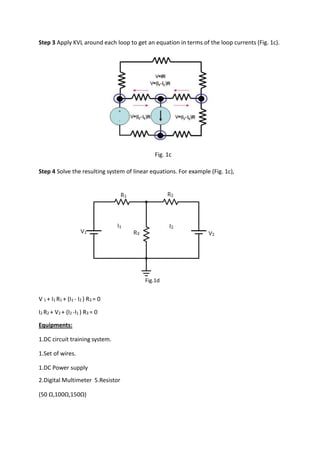
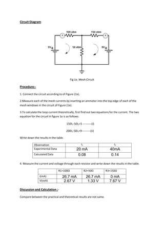
EXPT.NO.04
NAME OF THE EXPERIMENT: STUDY OF MESH ANALYSIS.
Objective: To solve a circuit using mesh analysis.
Theory :
Mesh analysis is a method through which the loop (or mesh) currents of a network can be
determined. The branch currents of the network can then be determined directly from the
loop currents. To solve an N mesh circuit, a set of N simultaneous equations are needed.
There are several ways to derive a solution (i.e. Matrix algebra). Followings are the steps for
the mesh analysis method:-
Step1 Identify the number of basic meshes. Mesh is a closed loop network (Fig 1a).
Fig. 1a
Step 2 Assign a current to each mesh (Fig. 1b).
Fig. 1b
Step 3 Apply KVL around each loop to get an equation in terms of the loop currents (Fig. 1c).
Fig. 1c
Step 4 Solve the resulting system of linear equations. For example (Fig. 1c),
V 1 + I1 R1 + (I1 - I2 ) R3 = 0
I2 R2 + V2 + (I2 -I1 ) R3 = 0
Equipments:
1.DC circuit training system.
1.Set of wires.
1.DC Power supply
2.Digital Multimeter 5.Resistor
(50 Ω,100Ω,150Ω)
Fig.1d
Circuit Diagram:
Fig 1e. Mesh Circuit
Procedure:-
1. Connect the circuit according to of Figure (1e).
2.Measure each of the mesh currents by inserting an ammeter into the top edge of each of the
mesh windows in the circuit of Figure (1e).
3.To calculate the loop current theoretically, first find out two equations for the current. The two
equation for the circuit in figure 1e is as follows:
150I1-50I2=5 ---------(i)
200I2-50I1=9---------(ii)
Write down the results in the table.
Observation I1 I2
Experimental Data 20 mA 40mA
Calculated Data 0.08 0.14
4. Measure the current and voltage through each resistor and write down the results in the table.
R1=100Ω R2=50Ω R3=150Ω
I(mA) 26.7 mA 26.7 mA 0 mA
V(volt) 2.67 V 1.33 V 7.67 V
Discussion and Calculation :-
Compare between the practical and theoretical results are not same.
A A

EXpt 04 on EEE lab

  • 1.
    EXPT.NO.04 NAME OF THEEXPERIMENT: STUDY OF MESH ANALYSIS. Objective: To solve a circuit using mesh analysis. Theory : Mesh analysis is a method through which the loop (or mesh) currents of a network can be determined. The branch currents of the network can then be determined directly from the loop currents. To solve an N mesh circuit, a set of N simultaneous equations are needed. There are several ways to derive a solution (i.e. Matrix algebra). Followings are the steps for the mesh analysis method:- Step1 Identify the number of basic meshes. Mesh is a closed loop network (Fig 1a). Fig. 1a Step 2 Assign a current to each mesh (Fig. 1b). Fig. 1b
  • 2.
    Step 3 ApplyKVL around each loop to get an equation in terms of the loop currents (Fig. 1c). Fig. 1c Step 4 Solve the resulting system of linear equations. For example (Fig. 1c), V 1 + I1 R1 + (I1 - I2 ) R3 = 0 I2 R2 + V2 + (I2 -I1 ) R3 = 0 Equipments: 1.DC circuit training system. 1.Set of wires. 1.DC Power supply 2.Digital Multimeter 5.Resistor (50 Ω,100Ω,150Ω) Fig.1d
  • 3.
    Circuit Diagram: Fig 1e.Mesh Circuit Procedure:- 1. Connect the circuit according to of Figure (1e). 2.Measure each of the mesh currents by inserting an ammeter into the top edge of each of the mesh windows in the circuit of Figure (1e). 3.To calculate the loop current theoretically, first find out two equations for the current. The two equation for the circuit in figure 1e is as follows: 150I1-50I2=5 ---------(i) 200I2-50I1=9---------(ii) Write down the results in the table. Observation I1 I2 Experimental Data 20 mA 40mA Calculated Data 0.08 0.14 4. Measure the current and voltage through each resistor and write down the results in the table. R1=100Ω R2=50Ω R3=150Ω I(mA) 26.7 mA 26.7 mA 0 mA V(volt) 2.67 V 1.33 V 7.67 V Discussion and Calculation :- Compare between the practical and theoretical results are not same. A A