This paper presents a parametric model for a DC geared motor used in a fish feeder machine, developed using experimental datasets analyzed through a particle swarm optimization (PSO) technique. The study measures input voltage and output speed, optimizing the model parameters to minimize mean square error (MSE). The final model demonstrated the best performance after ten trials, with a recorded time of 153.74 seconds and an MSE of 0.033142, suggesting its potential for future controller design.
![International Journal of Electrical and Computer Engineering (IJECE)
Vol. 9, No. 3, June 2019, pp. 1576~1584
ISSN: 2088-8708, DOI: 10.11591/ijece.v9i3.pp1576-1584 1576
Journal homepage: http://iaescore.com/journals/index.php/IJECE
Experimental dataset to develop a parametric model based of
DC geared motor in feeder machine
Azlan, W. M.1
, Salleh, S.M.2
, Mahzan, S.3
, Sadikin, A.4
, Ahmad, S.5
1,3,4,5
Faculty of Mechanical and Manufacturing Engineering, Universiti Tun Hussein Onn Malaysia, Malaysia
2
Mechanical Failure Prevention and Reliability (MPROVE), Department of Engineering Mechanics, Malaysia
Article Info ABSTRACT
Article history:
Received Aug 10, 2018
Revised Nov 20, 2018
Accepted Dec 11, 2018
This paper presents the application of a System Identification based on
Particle Swarm Optimization (PSO) technique to develop parametric model
of experimental dataset of DC Geared motor in feeder machine. The
experimental was conducted to measure the input (voltage) and output
(speed) data. The actual data is used to be optimized using PSO algorithm.
The parameter emphasized is Time, Man Square Error (MSE) and Average
Time. One of the best model has been chosen based on the optimum
parameters.Keywords:
DC geared motor
Parametric model
Particle swarm optimization
System identification
Copyright © 2019 Institute of Advanced Engineering and Science.
All rights reserved.
Corresponding Author:
Salleh, S.M.,
Department of Engineering Mechanics,
Faculty of Mechanical and Manufacturing Engineering,
101 Pt Raja, Batu Pahat, Johor, Malaysia.
Email: saliha@uthm.edu.my
1. INTRODUCTION
One of the factors that influence the growth rate of fish includes food dispersal system. A small
scale aquaculture or highly invested aquaculture project need to deliberate this feeder machine related to the
income profit [1]. Nowadays there are several fish food distributions systems was developed by researcher.
In April 1999, Anthony Cristopher Halford is the first researcher was developed an automatic fish feeder
system under intellectual pattern. The machine has been upgraded by Chang et. al. in 2005 by installing
Programmable Logic Controller (PLC) as a main controller [2]. In 2007, Ho et. al. was developed an
automatic fish feeder machine and used a microcontroller to generate 12 V DC motor at full speed [3].
DC motor are mostly used in industrial field which is in robotic control systems, transportation
control system and other applications due to their dynamic and efficiency characteristics compatible with
most mechanical loads [4]. The performance of the DC motor system may be influenced by some
possibilities which is changes in load dynamic, variable, disturbance and unpredictable inputs, unknown
parameters. Therefore, the motor must be analysed and controlled [5].
There are several researches that emphasized on application and analysis of DC motor.
The measured data which comprise input and output as experimental dataset were used to develop a DC
motor model bye identification process. Ye Naung et. al., 2018, implemented data driven approach to be used
in system identification process and controlled a system DC motor-based. In this research, DC motor is a
hardware part where the data input voltage and output speed have been recorded. The recorded data is used to
execute system identification process by using basic modelling similar with real DC motor by using simscape
electronic system to obtain the data of input voltage and output speed of DC motor. This research is to
identify the system using toolbox and nonlinear autoregressive with exogenous input (NARX) neural](https://image.slidesharecdn.com/1417270-200724025656/75/Experimental-dataset-to-develop-a-parametric-model-based-of-DC-geared-motor-in-feeder-machine-1-2048.jpg)
![Int J Elec & Comp Eng ISSN: 2088-8708
Experimental dataset to develop a parametric model based of DC geared motor in feeder… (Azlan, W. M.)
1577
network. The input voltage and output speed were measured from the dc motor which also known as
actuator [6].
2. SYSTEM DESCRIPTION
The structure of feeder machine consists of two parts. The first part used a storage which can put up
to 5 kg pallet. At this part, the drop mechanism uses silicone blades before the pallet spread into channels by
four blades. The distribution blade is driven by a 12 Volts DC Geared motor equipped encoder with
maximum speed 265 RPM and 3 kg/cm torque. The speed range of 255 PWM was used to drive the
distribution blade and push out the fish pallets into targeted area which is pond or cages. The machine was
also powered by Arduino microcontroller to give commands to DC Geared motor that attached on dispenser
and distribution part through motor driver. However, the DC Geared motor on distribution process during
motion and friction with its contact on the DC geared motor at distribution part. Figure 1 shows the real setup
of the machine.
Figure 1. Automatic fish feeder machine and experimental setup
3. EXPERIMENTAL DATASET
The feeder system can be represented by determining the input and output by experimental set his
section, it is explained the results of research and atand develop the model as close as its system. In this
research, the experiment process was conducted on DC geared motor. The experiment purpose is to obtain
input and (voltage) and output (speed). Then, the recorded data will be used for system identification process
to build the model of the system. This identification process is intended to generate a transfer function in the
form parametric model which is ARX (autoregressive with external input) model.
Figure 2 described the experiment setup to measuring the input voltage of DC geared motor. DC
motor has been tested by setting the value of PWM 150 as minimum and 255 is maximum with scale
increase 1. The voltage sensor has been used to determine the voltage produced by DC motor.
Figure 2. An illustrated of equipment setup to record the input voltage](https://image.slidesharecdn.com/1417270-200724025656/75/Experimental-dataset-to-develop-a-parametric-model-based-of-DC-geared-motor-in-feeder-machine-2-2048.jpg)
![ ISSN: 2088-8708
Int J Elec & Comp Eng, Vol. 9, No. 3, June 2019 : 1576 - 1584
1578
Firstly, the machine was switched on. Then the voltage sensor was used to measure the voltage
value of DC geared motor. The workspace recorded the real-time voltage reading.
In recording the output speed of DC motor, Matlab/Simulink was used to construct algorithm for
interfacing the machine and Arduino controller as shown in Figure 3. In this experiment, DC motor is turn
ON for 20 seconds for each PWM which in range 150-255.
Figure 3. Matlab/Simulink configuration
4. PARAMETRIC MODELLING
System identification encompasses parametric models of dynamical system using input and output
data of the system [7]. The flowchart to develop dynamic model using system identification is shown in
Figure 4. Based on Figure 4 above, there are four basic steps to develop the model. After the experiment and
recording of dataset as in experiment section, a parametric model structure need to determined.
A parametric model structure is also known as a black box model, which determines continuous or
discrete time system. The principle of system identification based on parametric model is to create
mathematical models guided by actual data.
Figure 4. The flow of system identification process [8]](https://image.slidesharecdn.com/1417270-200724025656/75/Experimental-dataset-to-develop-a-parametric-model-based-of-DC-geared-motor-in-feeder-machine-3-2048.jpg)
![Int J Elec & Comp Eng ISSN: 2088-8708
Experimental dataset to develop a parametric model based of DC geared motor in feeder… (Azlan, W. M.)
1579
ARX ARMAX model can be used as a representative for a particular system. This research used
ARX model in the methodology. The ARX model structure is simple in parametric structure which can be
return in (1):
𝐴(𝑞−1)𝑦(𝑘 − 𝑛) = 𝑞−𝑑 𝐵(𝑞−1)𝑢(𝑘 − 𝑛) + 𝑒(𝑘) (1)
𝐴(𝑞−1) and 𝐵(𝑞−1) are polynomial to be estimated. For the ARX the polynomial 𝐶(𝑞−1) = 1.
These polynomials represent the overall dynamical systems where (2) and (3) are defined as follow:
𝐴(𝑞−1) = 1 + 𝑎1 𝑞−1
+ ⋯ + 𝑎 𝑛𝑎 𝑞−𝑛𝑎
(2)
𝐵(𝑞−1) = 𝑏0 + ⋯ + 𝑏 𝑛𝑏 𝑞−𝑛𝑏 (3)
𝑢(𝑘) and 𝑦(𝑘) represent the input and output of the systems and 𝑒(𝑘) is a white noise signal, k is time unit
and (𝑞−1) represent the delay operator. Variables 𝑎𝑖, 𝑏𝑗, are the model parameters to be estimated, with 𝑖 =
1, … . 𝑛 𝑎 , 𝑗 = 1, … . 𝑛 𝑏. The minimum value of 𝑛 is supposed to be equal to 0.
4.1. Particle swarm optimization (PSO)
Particle Swarm Optimization (PSO) is the evolutionary technique (a search method based on a
natural system) was developed by Kennedy and Eberhart [9]-[14]. The system initially had random selective
populations. Each solution is potentially called particles while each particle is given a random velocity and
flown through the problem space. The particles have memory and each particle tracks the previous best
position called (P_best) and the corresponding fitness. There are a number of (P_best) for their respective
particles in swarm and the greatest fitness is called the global best, (G_best) of the swarm. The basic concept
of PSO technique is located in accelerating each particle towards the (P_best) and (G_best) location, with a
random weight acceleration at each step. The equation used in particle swarm optimization as follows (4)
and (5):
𝑉𝑖𝑑 = 𝜔 × 𝑉𝑖𝑑 + 𝐶1 𝑥 × (𝑃𝑔𝑑 − 𝑋𝑖𝑑) +𝐶2 × 𝑟𝑎𝑛𝑑2 × (𝑃𝑔𝑑 − 𝑋𝑖𝑑) (4)
𝑋𝑖𝑑 = 𝑋𝑖𝑑 + 𝑉𝑖𝑑 (5)
where 𝑋𝑖𝑑 and 𝑉𝑖𝑑 represent the velocity and position of the 𝑖𝑡ℎ particle with d dimensions respectively.
Rand1 and rand2 are two uniform random functions, and 𝜔 is the inertia weight, early selected.
PSO has many parameters and this is illustrated as follow: called inertia weight that controls
exploitation and exploration of search space cause dynamically adjust velocity 𝑉𝑚𝑎𝑥 is the maximum
allowable velocity for the particles for the example, “in this case where the velocity of the particles
exceeds 𝑉𝑚𝑎𝑥, then it is limited to 𝑉𝑚𝑎𝑥”. Therefore, the resolution and fitness of search depending on 𝑉𝑚𝑎𝑥.
If the 𝑉𝑚𝑎𝑥 is too high, then the particles will move beyond a good solution. If the 𝑉𝑚𝑎𝑥 is too low,
the particles will be trapped in local minima. The value C1 and C2 constants in (4) and (5), each are referred
to as cognition and social components. Figure 5 shows the general flow chart of the PSO algorithm.
Figure 5. The general flow chart of the PSO algorithm](https://image.slidesharecdn.com/1417270-200724025656/75/Experimental-dataset-to-develop-a-parametric-model-based-of-DC-geared-motor-in-feeder-machine-4-2048.jpg)
![ ISSN: 2088-8708
Int J Elec & Comp Eng, Vol. 9, No. 3, June 2019 : 1576 - 1584
1580
In optimization process there is criteria to minimize all of parameter. In this research, the estimated
model is based on the criteria of mean square error (MSE) value. The parameter estimation principle as show
in Figure 6.
Figure 6. Parameter Estimation Based on MSE
4.2. Validation model
The final step of the system identification process is validation model. The measured and desired
data is used in validation process. It is the difference between the values estimated by estimator and the true
value of quantity being estimated. The lower the value of MSE, the lower the value of error. MSE shows the
cumulative square error between the original and reconstructed image. The MSE equation can be
written in (6).
𝑀𝑆𝐸 = ∑
[𝐼1(𝑚, 𝑛) − 𝐼2(𝑚, 𝑛)]2
𝑀 ∗ 𝑁
(6)
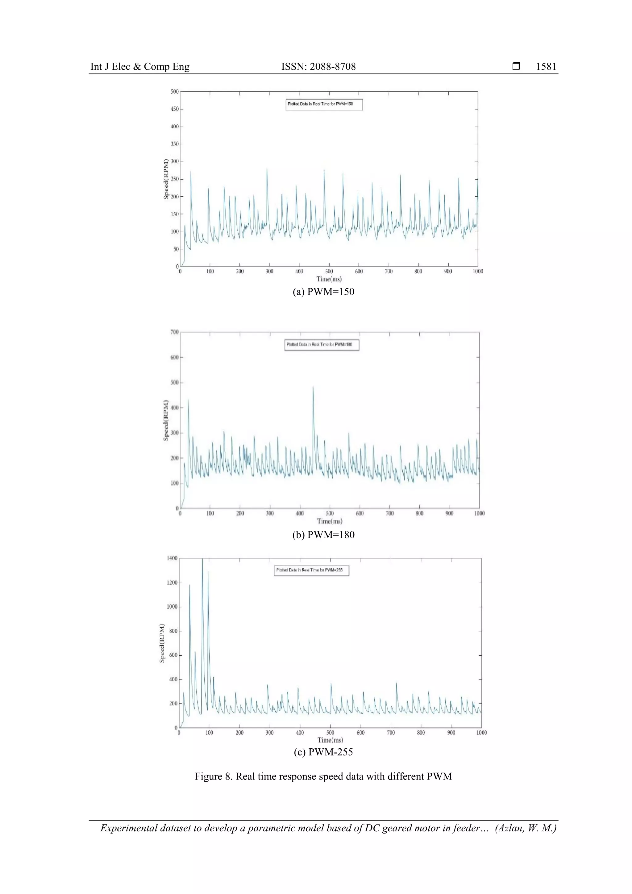
5. RESULT
The result will include dataset of input and output response and the parameters from trials using
PSO algorithm. Figure 7 show the performance response of the input voltage. The graph shows the increase
the value of PWM, the increase the voltage produced.
Figure 7. The respond of voltage versus PWM
The experiments had been carried out from different PWM and speed response had been recorded as
Figure 8. All of the data which represented the system will be proceeded to develop the model.](https://image.slidesharecdn.com/1417270-200724025656/75/Experimental-dataset-to-develop-a-parametric-model-based-of-DC-geared-motor-in-feeder-machine-5-2048.jpg)
![Int J Elec & Comp Eng ISSN: 2088-8708
Experimental dataset to develop a parametric model based of DC geared motor in feeder… (Azlan, W. M.)
1583
Based on the result obtained in the Table 1 and convergence of MSE in each trial a shown in
Figure 10, the most suitable model is the first trial with the lowest recorded time is 153.74 seconds, lowest
mse is 0.033142, number of iteration is 343 and total average time is 0.4482 seconds. The best selected
model as given in (7).
𝑌(𝑠) =
2.483𝑠 − 1902
𝑆2 + 41.4𝑠 + 6192
(7)
6. CONCLUSION
In this paper, the parametric model for fish feeder system was developed based on measured data
input (voltage) and output (speed). Ten trials have been simulated to obtain the best model from dataset of
DC geared motor using system identification based on PSO algorithm approach as ARX model. Therefore,
the first trial has generated the best model based on the recorded time value of the lowest is 153.74 seconds,
the lowest MSE is 0.033142, and the lowest average time value is 0.4482 seconds. The developed model with
minimum means squared error has been achieved and to be proceeded for controller design in future study.
ACKNOWLEDGEMENTS
This research is supported by the Pascasiswazah (GPPS) grant UTHM.RMC.600-5/1/10(98). Project
Vot. Number U967, under Research Management Centre (RMC), University of Tun Hussein Onn Malaysia.
REFERENCES
[1] FAO, "The State of World Fisheries and Aquaculture 2016: Contributing to Food Security and Nutrition for All,"
Rome, 2016.
[2] National Plan of Action for Management of Fishing. (2015)
[3] F. Huntingford, M. Jobling & S. Kadri, “Aquaculture and Behavior,” Wiley-Blackwell, 2012.
[4] Chang, C. M., Fang, W., Jao, R. C., Shyu, C. Z., & Liao, I. C., “Development of an Intelligent Feeding Controller
For Indoor Intensive Culturing of Eel,” Aquacultural Engineering, vol. 32, no. 2, pp. 343-353, January 2005.
[5] K.W. Hor, S.M Salleh, Abdullah, Mohd Ezree, Zaman, I., M.H. Hatta, S. Ahmad, A.E Ismail, W.A.W Mahmud,
“Improvement of Automatic Fish Feeder Machine Design,” Journal of Physics: Conference Series, vol. 914, no. 1,
2017.
[6] D.G. Sendrescu, “DC Motor Identification Based on Distributions Method,” Ann. Univ. Craiova, vol. 9, no. 36, pp.
41–49, 2012.
[7] Y. Naung, A. Schagin, H. L. Oo, K. Z. Ye and Z. M. Khaing, “Implementation of data driven control system of DC
motor by using system identification process,” IEEE Conference of Russian Young Researchers in Electrical and
Electronic Engineering (EIConRus), Moscow, pp. 1801-1804, 2018.
[8] C. Agarwal and A. Gupta, “Modeling, simulation based DC motor speed control by implementing PID controller
on FPGA,” Confluence 2013: The Next Generation Information Technology Summit (4th International
Conference), Noida, pp. 467-471, 2013.
[9] L.Jung, “System Identification,” Technical report, Wiley Encyclopedia of Electrical and Electronics Engineering,
no. LiTH-ISY-R-2809, 2007.
[10] L.Jung, “System Identification: Theory for The User,” Prentice Hall, 1999.
[11] J. Kennedy and R. Eberhart, “Particle Swarm Optimization,” Proceedings, IEEE International Conf. on Neural
Networks, vol. 4, pp.1942–1948, 1995.
[12] Y. Shi and R. Eberhart, “Empirical Study of Particle Swarm Optimization,” Proceedings of the 1999 Congress on
Evolutionary Computation, Vol. 3, 1999.
[13] R. Eberhart and Y Shi, “Particle Swarm Optimization: Developments, Applications and Resources,” Proceedings
of the 2001 Congress on Evolutionary Computation, vol. 1, pp. 81-86, 2001.
[14] Y. Shi and R. Eberhart, “Parameter Selection in Particle Swarm Optimization,” Proc. Seventh Annual Conf. on
Evolutionary Programming, pp. 591-601, 1998.](https://image.slidesharecdn.com/1417270-200724025656/75/Experimental-dataset-to-develop-a-parametric-model-based-of-DC-geared-motor-in-feeder-machine-8-2048.jpg)


![[000007]](https://cdn.slidesharecdn.com/ss_thumbnails/000007-211028000533-thumbnail.jpg?width=640&height=640&fit=bounds)
![[000008]](https://cdn.slidesharecdn.com/ss_thumbnails/000008-211028000724-thumbnail.jpg?width=640&height=640&fit=bounds)