Study Percentage Differential Relay Characteristics
•
0 likes•2,075 views

The document summarizes an experiment on a percentage differential relay. The experiment had three aims: to study the operating characteristics of the relay at 15% and 30% bias settings, to use the relay for single-phase transformer protection, and to study the harmonic restraint feature. Observations showed that increasing the bias setting required more current to trigger the relay. Testing the relay on a single-phase transformer demonstrated it would only operate for internal faults, verifying its protection zone. Introducing a DC branch also demonstrated the relay's harmonic restraint by increasing its tripping current.

Recommended
More Related Content
What's hot
What's hot (20)
Similar to Study Percentage Differential Relay Characteristics
Similar to Study Percentage Differential Relay Characteristics (20)
More from Umang Gupta
More from Umang Gupta (20)
Recently uploaded
Recently uploaded (20)
Study Percentage Differential Relay Characteristics
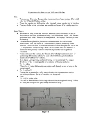
- 1. Experiment 04: Percentage Differential Relay Aim: To study and determine the operating characteristics of a percentage differential relay for 15% and 30% bias setting To use the transformer differential relay forsingle phase transformer protection To study the harmonic restrained feature of transformer differential protection Basic Theory: A differential relay is one that operates when the vectordifference of two or more similar electricalquantities exceeds a pre-determined value. Thus the two quantities must have a phase difference(approx. 180 degrees) for the operation of the relay. The Merz-Pricedifferential protectionscheme assumes that twocurrent transformers used are identical. This however is not true, especially under transient conditions. Due to different amounts of residual magnetism one of the CTs may saturate earlier during a short circuit current and thus the twoCTs transform their primary currents differentially even fora through fault condition. To accommodatethis feature, the “biased differential protectionscheme” or “percentage differential scheme” is used: wherein the relay is biased as a modification to Merz Pricescheme. As in figure 1, an operating and a restraining coil is connected.The torque developed by the operating coil is proportional to the ampere turns: T (i1 – i2) n0 Where (i1 – i2) is the differential current through the coil, n0: no. of turns in the operating coil T (i1 + i2) n0/2 Torque due to restraining coil is proportional to the equivalent current in restraining coiltimes the no. of turns in restraining coil. Thus: 2(i1 – i2)/(i1 + i2) = nr/ no The ratio of the differential operating current to the average restraining current is a fixed percentage in the “percentage differential relay”. Figure1
- 2. Apparatus used: 1. Ammeters – 15A – 2 2. Ammeter – 5 A – 1 3. Autotransformers -2 4. Rheostats – 100 ohm, 5A-2 5. Current transformers -2 6. Percentage differential relay -1 Observations: Study of operating characteristics of a percentage differential relay: a) Bias = 15% i1 (A) i1 – i2 (A) i2 (A) 1.9 0.32 1.65 2.09 0.39 2.5 3.35 0.48 3.0 4.05 0.72 4.72 b) Bias = 30% i1 (A) i1 – i2 (A) i2 (A) 1.6 0.62 2.25 2.75 0.75 2.05 3.65 1.0 2.7 4.25 1.18 3.15 c) Bias = 45% i1 (A) i1 – i2 (A) i2 (A) 2.3 0.9 1.5 3.1 1.18 2.0 4.0 1.5 2.55 Following are the plots of the ratio of differential operating current to the average restraining current forthe three cases:
- 3. Using the differential relay scheme fora single-phase transformer protection as in figure 2, it is observed that the relay does not operate fora fault outside the protection zone, howevera short circuitfault inside the protection zone triggers the relay. Figure2 To verify the harmonic restrained feature of transformer differential protection, a circuit as in figure 3 is created. It is observed that with the DC branch connected the relay trips at around 0.88A; withoutit, it trips at 0.2 A; thus verifyingthe restraint to current harmonics demonstrated by the scheme. Figure3 Conclusion: The plot of differential current vs. average restraining current is a straight line in a percentage differential relay More the relay bias setting, more will the initial amount of current required to trigger the relay The percentage differential relay protection scheme displays harmonic restraint.