This document provides instructions for diagnosing, servicing, and aligning vehicle lamps. It includes:
1. Safety precautions and general information for lamp diagnosis, service, and alignment.
2. Procedures for diagnosing issues with headlamps, fog lamps, and headlamp delay modules.
3. Instructions for servicing lamp bulbs, sockets, and connectors.
4. A process for preparing a vehicle and aligning its headlamps using a screen or alignment tool to ensure beams are properly adjusted.
This document provides information on servicing batteries, starters, and generators. It discusses general information on these components and their related systems. The document then provides specific procedures for removing and installing batteries, cleaning battery terminals, and removing and installing starters. It also identifies locations of related components like the starter relay.
1) It is important to read the safety instructions before operating the engine.
2) The document provides instructions on installing and adjusting the engine, carburetor, and glow plug.
3) Proper fuel, glow plug selection, and maintenance are emphasized to ensure best performance and engine life.
1) It is important to read the safety instructions before operating the engine.
2) The document provides information on installing and operating the O.S. engine, including parts identification, fuel and propeller selection, starting procedures, and maintenance tips.
3) Refer to the safety instructions and warnings before attempting to start or operate the engine.
This document provides instructions for safely operating and maintaining a model engine. It is important to read all safety instructions before operating the engine. The document outlines the necessary tools and accessories needed to operate the engine and provides details on installing the glow plug, carburetor and engine. It also provides information on starting, running and caring for the engine.
This document provides information about power steering systems. It includes sections on the power steering pump, gear, and linkage. The pump uses pressurized fluid to assist steering. It can be tested for pressure and flow. Issues like noise, binding, and poor return to center are diagnosed. Causes and repairs are outlined. The document also provides removal and installation instructions for the power steering pump.
This document provides information about the AX15 5-speed manual transmission used in Jeep XJ vehicles, including:
- The AX15 is a synchromesh manual transmission with 5 forward gears and 1 reverse gear. Fifth gear is an overdrive with a ratio of 0.79:1.
- Diagnosis of common issues like hard shifting, low lubricant level, and transmission noise are discussed along with their potential causes.
- Specifications like lubricant type, gear ratios, component locations, and service procedures are outlined.
This document provides information about front suspension components and alignment specifications for a vehicle. It describes the front suspension system which uses upper and lower control arms, coil springs, shock absorbers, and a stabilizer bar. It provides instructions for inspecting, diagnosing, and adjusting components like wheel bearings, ball joints, and toe alignment. Specifications are given for caster, camber, toe alignment, and torque values for fasteners.
The document provides information on ignition systems for 2.5L 4-cylinder and 4.0L 6-cylinder engines, including:
- The ignition system is controlled by the powertrain control module (PCM) and consists of spark plugs, ignition coil, distributor with camshaft position sensor, and various sensors.
- The distributor houses the camshaft position sensor which provides fuel injection synchronization. It does not have adjustable timing.
- The crankshaft position sensor mounted on the transmission bellhousing provides engine speed and position to the PCM.
This document provides an overview and descriptions of the key components in a vehicle starting system, including the starter relay, starter, and starter solenoid. It describes how the starting system forms a high-amperage feed circuit to power the starter and a low-amperage control circuit. It explains how the starter relay connects these circuits to engage the starter motor when the ignition switch and transmission position allow starting. Troubleshooting and service procedures for the starter relay and starter are also covered.
This document provides information on power mirror systems. It describes the major components, including the door module, power mirror switch, and power mirror. It explains how the systems operate and are controlled. Diagnosis and testing procedures are outlined to check the fuse, switches, wiring, and mirror motors. Removal and installation instructions are provided for the door module, power mirror switch, and power mirror.
This document provides information about the cooling system for a 2.5L diesel engine. It includes descriptions of key cooling system components like the radiator, coolant tank, water pump, thermostat, hoses, belts, and fans. It also provides details on coolant type and maintenance procedures for the cooling system.
The document discusses the onboard diagnostic system of a vehicle. It describes how the system monitors components and circuits for faults, and stores diagnostic trouble codes (DTCs) when issues are detected. It outlines the various ways that technicians can retrieve and interpret DTCs to diagnose emission control problems. The system also continuously monitors for engine misfires and illuminates the malfunction indicator lamp if emissions thresholds are exceeded.
This document provides information about the cooling system for XJ vehicles. It discusses the components of the cooling system such as the radiator, fans, thermostat, hoses, water pumps and how coolant flows through the system. It also describes that the cooling system regulates engine temperature, maintains normal operating temperature and prevents overheating. The cooling system uses a water pump to circulate coolant which carries heat to the radiator and heater core to be transferred to ambient air.
The document discusses the frame and bumpers of the Jeep Grand Cherokee. It notes that the Grand Cherokee does not have a conventional frame, but rather a unitized body and frame construction made of high-strength steel. It describes how to diagnose collision damage and properly repair a unibody structure. The document provides removal and installation instructions for the front and rear bumpers, as well as the front and rear tow hooks. Measurement points for the frame are also indicated to ensure proper alignment during repair.
The document provides information about a vehicle speed control system, including:
- Major components of the system are a speed control servo, powertrain control module, vacuum reservoir, vehicle speed sensor, and speed control switch.
- The powertrain control module monitors the system and can store diagnostic trouble codes.
- Diagnosis procedures are provided for common problems like the vehicle speed sensor, speed control switch, and speed control servo.
- Removal and installation procedures are given for the speed control servo on different engine models.
This document provides information on the wiper and washer systems for XJ vehicles, including:
- Descriptions of the major components of the windshield wiper, rear wiper, and washer systems.
- Details on the operation of the windshield wiper motor and linkage, rear wiper motor, washer pump, reservoir, and nozzles.
- Diagnosis and testing procedures for the wiper and washer systems, including checks of the wiper switch, motors, and circuit breakers.
- Removal and installation instructions for components like the wiper arms, blades, motors, linkage, washer system parts, and switches.
This document provides an overview of fuel delivery systems for vehicles with 4.0L and 5.2L engines. It describes the components of the fuel pump module, which is mounted in the fuel tank and contains the electric fuel pump, fuel pressure regulator, and in-tank fuel filter. The fuel pressure regulator is no longer mounted on the fuel rail. Procedures are provided for releasing fuel system pressure before servicing, and for testing fuel system pressure.
This document provides information about diagnosing and servicing power window systems. It describes the major components, including the power window switch, motor, and circuit breaker. Diagnosis steps are outlined to troubleshoot issues like no windows operating or a single inoperative window. Service procedures are also included for removing and installing components like the window switch, motor, and regulator.
The document provides information about chime/buzzer warning systems on Grand Cherokee models. It describes the components of the system including the chime module, driver's door jamb switch, ignition key-in switch, headlamp switch, and driver's seat belt switch. Diagnosis and service procedures are outlined to test each component if the warning system is not functioning properly.
This document provides information about power seats in Jeep Grand Cherokee models. It describes the major components of the power seat system, including the power seat switch and three reversible motors that operate the seat adjustments. The document provides guidance on diagnosing issues with the power seat motors or switch, including continuity tests of the switch connections. It also outlines procedures for removing and installing the power seat switch and motor/adjuster assembly.
The document provides general information about emission control systems, including:
1) It describes the different emission control components and systems used on 4.0L and 5.2L engines.
2) It explains how the on-board diagnostic system checks for faults in emission components like the EGR and EVAP systems.
3) It provides an overview of the evaporative emission control system and its components like the EVAP canister.
The document provides information on servicing the front suspension and axle of a Grand Cherokee vehicle. It discusses components like the track bar, stabilizer bar, upper and lower suspension arms, coil springs, shock absorbers and bushings. The summary also covers procedures for front wheel alignment, diagnosis of noise/vibration issues, specifications and torque values.
The document provides information about manual transmissions and transfer cases used in Jeep vehicles, including:
- An index listing transmission and transfer case models covered
- Service information for the AX15 5-speed manual transmission, including identification, gear ratios, lubrication, diagnosis and repair procedures
- Procedures for transmission removal, disassembly, component inspection and installation
This document provides information about power window systems, including:
1) It describes the major components of power window systems, including door modules, power window motors, and power window switches.
2) It explains how the door modules house the front door power window and lock switches, and how the individual window switches control the corresponding motors.
3) It provides instructions for diagnosing issues like an inoperative window, including checking for continuity to ground and voltage supply to the door module.
This document provides information about vehicle identification numbers (VIN) and manufacturer plates:
- The VIN is located on the lower windshield and contains 17 characters that provide data about the vehicle. It is also imprinted on the body code plate and frame rail.
- A check digit at the ninth position is used to verify the authenticity of the vehicle. The formula for the check digit is confidential.
- The manufacturer plate includes the vehicle make, model, and production date and is usually located on the driver side door jamb.
This document provides information about lighting systems on a vehicle, including:
- General information on lighting systems and bulb applications.
- Diagnostic procedures for headlamp, fog lamp, and multi-function switch systems.
- Details on exterior lamp systems.
- Service procedures for replacing bulbs and lenses in various interior and exterior lamps.
The document provides information on ignition system components, operation, and diagnostics for Chrysler vehicles. It includes descriptions of components like the ignition coil, distributor, oxygen sensor, and powertrain control module. The diagnostics section provides testing procedures for components such as the camshaft position sensor, crankshaft position sensor, and oxygen sensors. It also discusses using the DRB scan tool and onboard diagnostics to test the ignition system.
The document provides information on turn signal and hazard warning systems. It describes the main components, which include a combination flasher, multi-function switch, turn signal indicator lamps, and turn signal lamps. It outlines procedures for diagnosing issues and testing components like the flasher and switch. Removal and installation instructions are provided for the multi-function switch and combination flasher.
This document provides information about the electrically heated systems in a vehicle, including:
- The defogger relay controls power to the rear window and outside mirror heating grids.
- The rear window has a heating grid made of conductive lines that heat the glass when powered.
- The instrument cluster monitors switch inputs and controls the defogger relay timing and logic.
- To diagnose the system, one can check for voltage at grids when the switch is on and feel for heating, or check for continuity in the circuits and repair any open lines.
This document provides information on horn systems, including descriptions and removal/installation procedures for the horn relay, horn switch, and horns. It describes the horn relay as an electromechanical device located in the junction block that switches battery current to the horns. The center-blow horn switch is integral to the driver's airbag module cover. Dual electromagnetic diaphragm horns are mounted behind the front bumper and connected in parallel. Diagnosis and testing procedures are provided for the horn relay, horn switch and horns.
The document describes the components and operation of a vehicle's passive restraint system. It includes airbag modules in the steering wheel and instrument panel, an airbag control module, impact sensors, and a clockspring. The airbag modules contain inflators that deploy the airbags in a collision. Proper handling and repair of the system is critical due to safety risks from accidental deployment.
The document provides information on airbag systems, including:
- Warnings about the sensitive nature of airbag components and need to disconnect the battery before working on the system.
- Descriptions of major airbag system components like the airbag module, impact sensors, and airbag control module.
- Procedures for diagnosing airbag systems using a scan tool and checking for diagnostic trouble codes.
- Guidelines for handling undeployed and deployed airbag modules and cleaning up after a deployment.
- Steps for removing and installing airbag modules and impact sensors.
This document provides information about a vehicle's chime warning system, including:
- The system warns the driver if the seat belt is not fastened, temperatures are high, lights are on with the ignition off and door open, or the key is in the ignition with the door open.
- It describes the major components of the system: the driver door jamb switch, driver seat belt switch, headlamp switch, instrument cluster, and key-in ignition switch.
- Diagnosis and testing procedures are provided for each component to determine if it is functioning properly.
8w97 Power Distribution Maintenance ManualRimsky Cheng
The document describes the power distribution system for a vehicle. It includes the Totally Integrated Power Module (TIPM) which centralizes power distribution and protection. The TIPM contains fuses, relays and a microprocessor. It provides primary voltage distribution and protection. The document discusses TIPM description, operation, removal and installation procedures. It also describes the ignition-off draw fuse and cigar lighter outlet components.
This document provides information about a vehicle speed control system, including:
1) It describes the major components of the speed control system including the powertrain control module, speed control servo, switches, stop lamp switch, vacuum reservoir, and vehicle speed sensor.
2) It explains how the system operates and the functions of the components like using vacuum to control throttle position via the servo and switches to control settings.
3) It provides information on diagnosing and testing the system including onboard diagnostic tests, electrical tests of components, and checking for issues like loose connections or faulty switches.
The document provides information about power seat systems. It describes the major components, including the circuit breaker, power seat adjuster/motors, and power seat switch. The circuit breaker protects the system from overloads. Three motors control the six-way adjustment of the seat. If a component fails, the entire adjuster/motor assembly must be replaced. Testing and diagnosis procedures are outlined to troubleshoot issues with the circuit breaker, adjuster/motors, or switch. Removal and installation steps are also provided.
Service Manual 2007 Evinrude E-tec 115-150-175-200 Hp 60° V.pdfHannuLeinonen5
This document provides safety information and registered trademarks for Bombardier Recreational Products Inc. outboard motors. It lists numerous safety warnings regarding working on outboard engines, including dangers of rotating propellers, exhaust gas, electrical shock, and flammable fuels. Registered trademarks are also listed for various component manufacturers and BRP products.
The document provides general information about power locks on a Grand Cherokee vehicle. It describes the major components, including power lock switches, relays, motors, and the keyless entry transmitter and module. It provides diagnosis procedures to test the different systems and components. It also lists the steps to remove and install various parts like the power lock switch, motors, and to program a new keyless entry transmitter.
2007 johnson evinrude outboard 90 hp service repair manualfujsjefjskemm
This document provides information on safety procedures, trademarks, and copyrights related to servicing outboard engines. It lists numerous safety warnings and alerts technicians to avoid personal injury when working with engines. Technicians are instructed to only use authorized genuine parts, follow torque specifications, and use recommended service tools. Failure to follow safety precautions could result in severe injury, death or property damage.
2007 johnson evinrude outboard 90 hp service repair manualfjeskfksmefmm
This document provides information on service manuals for Evinrude outboard motors, including:
- The service manual covers Evinrude E-TEC 3-cylinder 79 cubic inch models.
- The parts catalog should be used with the service manual for part numbers and exploded views.
- Model and serial numbers are used to identify specific outboard models and options.
2007 johnson evinrude outboard 75 hp service repair manualfjkseksmefmm
This document provides information on trademarks and registered trademarks for various component manufacturers. It lists trademarks such as AMP, Champion, Dexron, Evinrude, Fluke, Johnson, Locquic, NGK, Packard, Permatex, and Snap-on that are registered to their respective manufacturing companies. The document also lists trademarks owned by BRP such as Carbon Guard, E-TEC, FasTrak, Grease, Hi-Vis, Lubriplate, Moly Lube, Nut Lock, Outboard Oil, Triple-Guard, and Ultra that are used on Evinrude and Johnson outboard motors.
2007 johnson evinrude outboard 75 hp service repair manualfujsjfejkskem
This document provides information on safety procedures, trademarks, and copyrights related to servicing outboard motors. It lists numerous safety warnings and alerts technicians to avoid personal injury when working with electrical systems, fuel systems, and rotating parts. Technicians are instructed to only use authorized replacement parts and follow torque specifications.
This document is the user manual for the Bolt VM-110 LED Macro Ring Light. It describes how to install batteries, mount the ring light and power control unit to a camera, use the included diffusers, turn on the light and select different lighting modes, and adjust the brightness level. The manual provides instructions on operating the ring light and an overview of its features to help users get the best performance from the product.
This document provides information about steering systems for ZJ vehicles. It describes the major components of the power steering system including the recirculating ball steering gear, steering linkage, power steering pump, and steering column. It provides details on identifying codes for the steering gear and pump as well as diagnosing common noise complaints.
The document provides information about rear suspension and axles for a Grand Cherokee vehicle. It describes the main components of the rear suspension system, including coil springs, upper and lower suspension arms, shock absorbers, stabilizer bar, track bar, and jounce bumpers. It also explains how the standard differential allows the axle shafts to rotate at different speeds when turning corners to compensate for the longer path of the outside wheel. The Model 35 axle used in the Grand Cherokee can be equipped with an optional Trac-Lok limited slip differential.
This document appears to be an electronic service manual for the 1995 Jeep Grand Cherokee. The logo on the page links to instructions when clicked. The page requests the user click the link for further information.
The document provides information on standard service procedures for engines, including form-in-place gaskets, honing cylinder bores, measuring crankshaft and connecting rod bearing clearances using Plastigage, repairing damaged or worn threads using a Heli-Coil tap, and servicing a 4.0L engine assembly (short block). It includes diagrams and step-by-step instructions for compression testing, measuring bearing clearance, and honing cylinder bores. Tables of contents and indexes provide page references for additional information on specific engines and procedures.
This document provides information about power mirrors and an automatic day/night rear view mirror on Jeep Grand Cherokee models. It describes the major components of these systems and their functions. The document also provides diagnostic procedures to test the power mirror switch and motors, as well as the automatic rear view mirror. Finally, it lists the service procedures for removing and installing the power mirror switch and removing the power mirrors and automatic rear view mirror.
The document discusses various exterior body components of a vehicle. It provides removal and installation instructions for components like the grille, headlamps, hood, hood latches and related parts. The document is organized in sections covering the grille/reinforcement, radiator support, hood, hood hinges/latches/striker and other exterior parts. Diagrams and step-by-step instructions are provided for servicing these exterior body parts.
This document provides information about a vehicle theft alarm system, including:
- General descriptions of how the system arms, disarms, and responds to unauthorized access attempts.
- Instructions for performing self-diagnosis tests to check the operation of sensors and circuits.
- Procedures for technicians to remove and install the VTA module, which involves removing various dash panel components.
- Steps for technicians to diagnose the system using the self-diagnosis mode and by checking for proper horn responses from sensors.
This document contains information about brakes for a vehicle model. It includes sections on general brake information, ABS brakes, changes for the 1995 model year, brake components, fluids and cleaning products, safety precautions, and an index of topics. The key points are:
- The vehicle uses power assisted four-wheel disc brakes with ABS standard on all models.
- Changes for 1995 include different master cylinder, power brake booster, and hydraulic control unit components for the ABS system.
- Safety precautions for working on brakes include wearing protective equipment and properly disposing of any potential asbestos dust.
This document provides information about exhaust systems and intake manifolds. It discusses the basic components of exhaust systems, including exhaust manifolds, pipes, catalytic converters, heat shields, mufflers and tailpipes. It describes symptoms of exhaust system problems and provides procedures for removing and installing exhaust pipes and manifolds. Intake manifolds and catalytic converters are also discussed.
The document provides information about the overhead console in Jeep Grand Cherokee models. It describes the different types of overhead consoles that are used depending on whether the vehicle has a power sunroof option. It also describes the major components in the overhead console including the trip computer, compass, thermometer, reading lamps, remote garage door opener storage, and sunglasses storage. The document provides details on diagnosing issues with these components through self-diagnostic tests and flow charts.
This document provides general information about audio systems for Jeep Grand Cherokee models. It describes components such as radios, speakers, antennas, and amplifiers. It also provides diagnostic procedures and service instructions for removing and installing these components.
This document provides information about cooling system diagnosis and service procedures for a vehicle. It includes:
- An overview of cooling system components and coolant routing
- Diagnosis charts to help identify potential causes of overheating
- Procedures for testing the water pump, draining and refilling the cooling system, and replacing components like the radiator, hoses, thermostat, and water pump.
- Cautions for working on the high-pressure cooling system and ensuring the correct rotating water pump is installed.
This document provides contact information for obtaining special service tools in the United States, Canada, and internationally. The same tools or their equivalent are required for certain vehicle service operations and can be obtained from local sources or through the listed contacts, which include addresses and phone/fax numbers for Miller Special Tools in Michigan and C&D Riley Enterprises in Ontario.
The document provides information about diagnosing issues with a vehicle's rear window defogger system. It describes the major components of the system, including the rear window glass grid, defogger switch, and defogger relay/timer. It then lists steps to test overall system operation and to isolate problems, such as using a voltmeter to check for breaks in the glass grid lines or testing power supply to the relay.
This document provides information on propeller shafts. It discusses:
1) There are three types of propeller shafts used on 4WD vehicles, differing by their joint configurations and whether they include a slip yoke.
2) Universal joints are used to allow the propeller shaft to operate at different angles and are not repairable if damaged.
3) Vibration can be caused by an unbalanced propeller shaft, worn or misaligned universal joints, or other vehicle component issues like loose engine mounts. Diagnosis procedures include measuring runout and clamping sections to isolate the source.
The document provides information on servicing a clutch system. It includes:
- Descriptions of clutch components and their functions.
- Procedures for diagnosing clutch problems through road testing, inspection of components for contamination, misalignment or excessive wear.
- Guidelines for checking flywheel and clutch disc runout and how to address issues found.
- Causes of clutch housing misalignment and how it can lead to premature wear.
- Charts outlining common clutch faults, their causes and recommended corrective actions.
- Steps for removal and installation of clutch cover/disc, housing, hydraulic linkage, pedal, pilot/release bearings and flywheel service.
The
This document provides instructions and cautions for automotive service professionals. It advises that all repair procedures should follow the manufacturer's recommendations. Special tools may be required for some procedures, and safety goggles should always be worn. Cautions are included to minimize risks of injury from components like clips and springs. The manufacturer cannot test all procedures, so service professionals must ensure personal and vehicle safety. Contact information is provided to order service manuals.
(1) The document provides general information about the horn system components in a Grand Cherokee, including the horn switch, horn relay, and horns.
(2) Diagnosis instructions check the fuse, horn relay connections, horn switch wiring, and horn ground before replacing components.
(3) Service procedures are provided for removing and installing the horn switch, horns, and horn relay. The horn switch is accessed through the steering wheel and airbag module. Horns are mounted under the right front fender. The horn relay is located in the relay center in the glove box.
This document is the 1995 Jeep Grand Cherokee service manual published by Chrysler Corporation. It provides service and repair instructions for technicians working on 1995 Jeep Grand Cherokee vehicles. The manual is divided into groups covering different vehicle systems. It notes that specific tools are required for some procedures and instructions on where to order them. The manual also reserves the right for Chrysler to make changes to vehicles or manuals without obligation.
Expanding Access to Affordable At-Home EV Charging by Vanessa WarheitForth
Vanessa Warheit, Co-Founder of EV Charging for All, gave this presentation at the Forth Addressing The Challenges of Charging at Multi-Family Housing webinar on June 11, 2024.
Charging Fueling & Infrastructure (CFI) Program Resources by Cat PleinForth
Cat Plein, Development & Communications Director of Forth, gave this presentation at the Forth and Electrification Coalition CFI Grant Program - Overview and Technical Assistance webinar on June 12, 2024.
EV Charging at MFH Properties by Whitaker JamiesonForth
Whitaker Jamieson, Senior Specialist at Forth, gave this presentation at the Forth Addressing The Challenges of Charging at Multi-Family Housing webinar on June 11, 2024.
Implementing ELDs or Electronic Logging Devices is slowly but surely becoming the norm in fleet management. Why? Well, integrating ELDs and associated connected vehicle solutions like fleet tracking devices lets businesses and their in-house fleet managers reap several benefits. Check out the post below to learn more.
Charging and Fueling Infrastructure Grant: Round 2 by Brandt HertensteinForth
Brandt Hertenstein, Program Manager of the Electrification Coalition gave this presentation at the Forth and Electrification Coalition CFI Grant Program - Overview and Technical Assistance webinar on June 12, 2024.
Charging Fueling & Infrastructure (CFI) Program by Kevin MillerForth
Kevin Miller, Senior Advisor, Business Models of the Joint Office of Energy and Transportation gave this presentation at the Forth and Electrification Coalition CFI Grant Program - Overview and Technical Assistance webinar on June 12, 2024.
Dahua provides a comprehensive guide on how to install their security camera systems. Learn about the different types of cameras and system components, as well as the installation process.
Understanding Catalytic Converter Theft:
What is a Catalytic Converter?: Learn about the function of catalytic converters in vehicles and why they are targeted by thieves.
Why are They Stolen?: Discover the valuable metals inside catalytic converters (such as platinum, palladium, and rhodium) that make them attractive to criminals.
Steps to Prevent Catalytic Converter Theft:
Parking Strategies: Tips on where and how to park your vehicle to reduce the risk of theft, such as parking in well-lit areas or secure garages.
Protective Devices: Overview of various anti-theft devices available, including catalytic converter locks, shields, and alarms.
Etching and Marking: The benefits of etching your vehicle’s VIN on the catalytic converter or using a catalytic converter marking kit to make it traceable and less appealing to thieves.
Surveillance and Monitoring: Recommendations for using security cameras and motion-sensor lights to deter thieves.
Statistics and Insights:
Theft Rates by Borough: Analysis of data to determine which borough in NYC experiences the highest rate of catalytic converter thefts.
Recent Trends: Current trends and patterns in catalytic converter thefts to help you stay aware of emerging hotspots and tactics used by thieves.
Benefits of This Presentation:
Awareness: Increase your awareness about catalytic converter theft and its impact on vehicle owners.
Practical Tips: Gain actionable insights and tips to effectively prevent catalytic converter theft.
Local Insights: Understand the specific risks in different NYC boroughs, helping you take targeted preventive measures.
This presentation aims to equip you with the knowledge and tools needed to protect your vehicle from catalytic converter theft, ensuring you are prepared and proactive in safeguarding your property.
1. XJ LAMPS 8L - 1
LAMPS
CONTENTS
page page
BULB APPLICATION . . . . . . . . . . . . . . . . . . . . . 15 LAMP DIAGNOSIS . . . . . . . . . . . . . . . . . . . . . . . 1
HEADLAMP ALIGNMENT . . . . . . . . . . . . . . . . . . 4 LAMP SERVICE . . . . . . . . . . . . . . . . . . . . . . . . 10
LAMP BULB SERVICE . . . . . . . . . . . . . . . . . . . . 7 LAMP SYSTEMS . . . . . . . . . . . . . . . . . . . . . . . 14
LAMP DIAGNOSIS
INDEX
page page
GENERAL INFORMATION DIAGNOSIS AND TESTING
DAYTIME RUNNING LAMP MODULE . . . . . . . . . 1 DIAGNOSTIC PROCEDURES . . . . . . . . . . . . . . 2
GENERAL INFORMATION . . . . . . . . . . . . . . . . . 1 FOG LAMP DIAGNOSIS . . . . .. . . . . . . . . . . . . . 3
SAFETY PRECAUTIONS . . . . . . . . . . . . . . . . . . 1 HEADLAMP DELAY MODULE . . . . . . . . . . . . . . 3
SENTINEL HEADLAMP DELAY MODULE . . . . . . 1 HEADLAMP DIAGNOSIS . . . .. . . . . . . . . . . . . . 2
GENERAL INFORMATION When it is necessary to remove components to ser-
vice another, it should not be necessary to apply
GENERAL INFORMATION excessive force or bend a component to remove it.
Each vehicle is equipped with various lamp assem- Before damaging a trim component, verify hidden
blies. A good ground is necessary for proper lighting fasteners or captured edges are not holding the com-
operation. Grounding is provided by the lamp socket ponent in place.
when it comes in contact with the metal body, or
through a separate ground wire. SENTINEL HEADLAMP DELAY MODULE
When changing lamp bulbs check the socket for The Headlamp Module delays the de-activation of
corrosion. If corrosion is present, clean it with a wire the headlamps for 45 Ϯ 15 seconds after the ignition
brush and coat the inside of the socket lightly with switch is turned OFF. The driver engages the module
Mopar Multi-Purpose Grease or equivalent. by turning the ignition switch OFF, then turning the
headlamps OFF.
SAFETY PRECAUTIONS
DAYTIME RUNNING LAMP MODULE
WARNING: EYE PROTECTION SHOULD BE USED The Daytime Running Lights (Headlamps) System
WHEN SERVICING GLASS COMPONENTS. PER- is installed on vehicles manufactured for sale in Can-
SONAL INJURY CAN RESULT. ada only. The headlamps are illuminated when the
ignition switch is turned to the ON position and the
vehicle is put into motion. The DRL module receives
CAUTION: Do not touch the glass of halogen bulbs a vehicle-moving signal from the vehicle speed sen-
with fingers or other possibly oily surface, reduced sor. This provides a constant headlamps-on condi-
bulb life will result. tion as long as the vehicle is moving. The lamps are
Do not use bulbs with higher candle power than illuminated at approximately 30 percent of normal
indicated in the Bulb Application table at the end of intensity.
this group. Damage to lamp can result.
Do not use fuses, circuit breakers or relays hav-
ing greater amperage value than indicated on the
fuse panel or in the Owners Manual.
2. 8L - 2 LAMPS XJ
DIAGNOSIS AND TESTING HEADLAMP DIAGNOSIS
Always begin any diagnosis by testing all of the
DIAGNOSTIC PROCEDURES fuses and circuit breakers in the system. Refer to
When a vehicle experiences problems with the Group 8W, Wiring Diagrams.
headlamp system, verify the condition of the battery Conventional and halogen headlamps are inter-
connections, charging system, headlamp bulbs, wire changeable. It is recommended that they not be
connectors, relay, high beam dimmer switch and intermixed on a given vehicle.
headlamp switch. Refer to Group 8W, Wiring Dia-
grams for component locations and circuit informa-
tion.
HEADLAMP DIAGNOSIS
CONDITION POSSIBLE CAUSES CORRECTION
HEADLAMPS ARE DIM 1. Loose or corroded battery cables. 1. Clean and secure battery cable clamps
WITH ENGINE IDLING OR and posts.
IGNITION TURNED OFF. 2. Loose or worn generator drive belt. 2. Adjust or replace generator drive belt.
3. Charging system output too low. 3. Test and repair charging system, refer to
Group 8A
4. Battery has insufficient charge. 4. Test battery state-of-charge, refer to
Group 8A
5. Battery is sulfated or shorted. 5. Load test battery, refer to Group 8A.
6. Poor lighting circuit Z1-ground. 6. Test for voltage drop across Z1-ground
locations, refer to Group 8W.
7. Both headlamp bulbs defective. 7. Replace both headlamp bulbs.
HEADLAMP BULBS 1. Charging system output too high. 1. Test and repair charging system, refer to
BURN OUT Group 8A
FREQUENTLY.
2. Loose or corroded terminals or 2. Inspect and repair all connectors and
splices in circuit. splices, refer to Group 8W.
HEADLAMPS ARE DIM 1. Charging system output too low. 1. Test and repair charging system, refer to
WITH ENGINE RUNNING Group 8A.
ABOVE IDLE.* 2. Poor headlamp circuit ground. 2. Test voltage drop across Z1-ground,
refer to Group 8W.
3. High resistance in headlamp circuit. 3. Test amperage draw of headlamp circuit.
4. Both headlamp bulbs defective. 4. Replace both headlamp bulbs.
HEADLAMPS FLASH 1. Poor headlamp circuit ground. 1. Repair circuit ground, refer to Group 8W.
RANDOMLY. 2. High resistance in headlamp circuit. 2. Test amperage draw of headlamp circuit.
3. Faulty headlamp switch circuit 3. Replace headlamp switch.
breaker.
4. Loose or corroded terminals or 4. Repair connector terminals or splices,
splices in circuit. refer to Group 8W.
HEADLAMPS DO NOT 1. No voltage to headlamps. 1. Replace fuse, refer to group 8W.
ILLUMINATE. 2. No ground at headlamps. 2. Repair circuit ground, refer to Group 8W.
3. Faulty headlamp switch. 3. Replace headlamp switch.
4. Faulty headlamp dimmer switch. 4. Replace headlamp dimmer switch.
5. Broken connector terminal or wire 5. Repair connector terminal or wire
splice in headlamp circuit. splices.
* Canada vehicles must have lamps ON.
3. XJ LAMPS 8L - 3
DIAGNOSIS AND TESTING (Continued)
FOG LAMP DIAGNOSIS
CONDITION POSSIBLE CAUSES CORRECTION
FOG LAMPS ARE DIM 1. Loose or corroded battery cables. 1. Clean and secure battery cable clamps
WITH ENGINE IDLING OR and posts.
IGNITION TURNED OFF. 2. Loose or worn generator drive belt. 2. Adjust or replace generator drive belt.
3. Charging system output too low. 3. Test and repair charging system, refer to
Group 8A
4. Battery has insufficient charge. 4. Test battery state-of-charge, refer to
Group 8A.
5. Battery is sulfated or shorted. 5. Load test battery, refer to Group 8A
6. Poor lighting circuit Z1-ground. 6. Test for voltage drop across Z1-ground
locations, refer to Group 8W.
7. Both fog lamp bulbs defective. 7. Replace both lamp bulbs.
FOG LAMP BULBS BURN 1. Charging system output too high. 1. Test and repair charging system, refer to
OUT FREQUENTLY. Group 8A.
2. Loose or corroded terminals or 2. Inspect and repair all connectors and
splices in circuit. splices, refer to Group 8W.
FOG LAMPS ARE DIM 1. Charging system output too low. 1. Test and repair charging system, refer to
WITH ENGINE RUNNING Group 8A.
ABOVE IDLE. 2. Poor fog lamp circuit ground. 2. Test voltage drop across Z1-ground,
refer to Group 8W.
3. High resistance in fog lamp circuit. 3. Test amperage draw of fog lamp circuit.
4. Both fog lamp bulbs defective. 4. Replace both fog lamp bulbs.
FOG LAMPS FLASH 1. Poor fog lamp circuit ground. 1. Repair circuit ground, refer to Group 8W.
RANDOMLY. 2. High resistance in fog lamp circuit. 2. Test amperage draw of fog lamp circuit.
3. Faulty fog lamp switch circuit 3. Replace fog lamp switch.
breaker.
4. Loose or corroded terminals or 4. Repair connector terminals or splices,
splices in circuit. refer to Group 8W.
FOG LAMPS DO NOT 1. Blown fuse for fog lamps. 1. Replace fuse, refer to group 8W.
ILLUMINATE. 2. No ground at fog lamps. 2. Repair circuit ground, refer to Group 8W.
3. Faulty fog lamp switch. 3. Replace fog lamp switch.
4. Broken connector terminal or wire 4. Repair connector terminal or wire
splice in fog lamp circuit. splices.
HEADLAMP DELAY MODULE (5) Turn headlamps on and measure voltage at ter-
minal 6. The voltmete should indicate battery volt-
DELAY FUNCTION INOPERATIVE age. If not repair open circuit between L2 and HDLP
(1) Ensure headlamps operate before proceeding. delay module.
(2) Remove, inspect and test the HDLP delay 10 (6) Measure the voltage between the delay module
amp fuse in junction box. Replace if defective. terminal 2 and vehicle body ground. The voltmeter
(3) With the key off and the connector discon- should indicate battery voltage. If not, repair the
nected, measure the resistance from the delay mod- open circuit in the wire harness to the HDLP fuse in
ule terminal 4 to vehicle body ground. The ohmmeter the PDC.
should indicate zero ohms. If not, repair the open cir- (7) If steps 1 through 6 prove out good, replace
cuit in the wire harness to vehicle body ground. headlamp delay module.
(4) With the key on measure the voltage between
the delay module terminal 8 and vehicle body
ground. The voltmeter should indicate battery volt-
age. If not, repair the open circuit in the wire har-
ness from ignition switch to HDLP delay module.
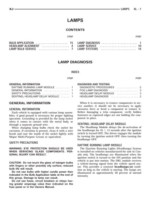
4. TO CENTER VEHICLE
CENTER OF OF HEAD-
LAMP LENS TOP EDGE OF HIGH TO CENTER
FLOOR INTENSITY ZONELEFT EDGE OF HIGH INTEN-
OF HEADLAMP LENS 7.62 METERS FEET)
SITY ZONE(25 VEHICLE CENTERLINE
FRONT OF HEADLAMP
8L - 4 LAMPS XJ
HEADLAMP ALIGNMENT
INDEX
page page
GENERAL INFORMATION HEADLAMP ADJUSTMENT . . . . . . . . . . . . . . . . 5
HEADLAMP ALIGNMENT . . . . . . . . . . . . . . . . . . 4 HEADLAMP ALIGNMENT PREPARATION . . . . . . 4
SERVICE PROCEDURES SPECIAL TOOLS
FOG LAMP ADJUSTMENT . . . . . . . . . . . . . . . . . 6 HEADLAMP ALIGNMENT . . . . . . . . . . . . . . . . . . 6
GENERAL INFORMATION SERVICE PROCEDURES
HEADLAMP ALIGNMENT HEADLAMP ALIGNMENT PREPARATION
Headlamps can be aligned using the screen method (1) Verify headlamp dimmer switch and high beam
provided in this section. Alignment Tool C-4466-A or indicator operation.
equivalent can also be used. Refer to instructions (2) Correct defective components that could hinder
provided with the tool for proper procedures. The proper headlamp alignment.
preferred headlamp alignment setting is 0 for (3) Verify proper tire inflation.
the left/right adjustment and 1” down for the (4) Clean headlamp lenses.
up/down adjustment. (5) Verify that luggage area is not heavily loaded.
(6) Fuel tank should be FULL. Add 2.94 kg (6.5
lbs.) of weight over the fuel tank for each estimated
gallon of missing fuel.
Fig. 1 Headlamp Alignment Screen—Typical
5. ADJUSTMENT
LEFT/RIGHT
HEADLAMP
SCREW UP/DOWN ADJUST-
MENT SCREW
XJ LAMPS 8L - 5
SERVICE PROCEDURES (Continued)
ALIGNMENT SCREEN PREPARATION (1) Remove screws and both headlamp bezels.
(1) Position vehicle on a level surface perpendicu- (2) Clean front of the headlamps.
lar to a flat wall 7.62 meters (25 ft) away from front (3) Place headlamps on LOW beam.
of headlamp lens (Fig. 1). (4) Cover front of the headlamp that is not being
(2) If necessary, tape a line on the floor 7.62 adjusted.
meters (25 ft) away from and parallel to the wall. (5) Turn vertical adjustment screw (Fig. 2) until
(3) Measure from the floor up 1.27 meters (5 ft) the headlamp beam pattern on screen/wall is similar
and tape a line on the wall at the centerline of the to the pattern depicted in the alignment screen fig-
vehicle. Sight along the centerline of the vehicle ure.
(from rear of vehicle forward) to verify accuracy of
the line placement.
(4) Rock vehicle side-to-side three times to allow
suspension to stabilize.
(5) Jounce front suspension three times by pushing
downward on front bumper and releasing.
(6) Measure the distance from the center of head-
lamp lens to the floor. Transfer measurement to the
alignment screen (with tape). Use this line for
up/down adjustment reference.
(7) Measure distance from the centerline of the
vehicle to the center of each headlamp being aligned.
Transfer measurements to screen (with tape) to each
side of vehicle centerline. Use these lines for left/
right adjustment reference.
HEADLAMP ADJUSTMENT
A properly aimed low beam will project the top Fig. 2 Headlamp Beam Adjustment Screws
edge of high intensity pattern on the screen from 50 NOTE: When using a headlamp aiming screen:
mm (2 in.) above to 50 mm (2 in.) below headlamp
centerline. The side-to-side left edge of high intensity • Adjust the headlamps so that the beam horizon-
pattern should be from 50 mm (2 in.) left to 50 mm tal position is at 0.
(2 in.) right of headlamp centerline). The preferred • Adjust the beam vertical position is 25 mm (1
headlamp alignment is 0 for the left/right in) downward from the lamp horizontal centerline.
adjustment and 1” down for the up/down (6) Rotate the horizontal adjustment screw until
adjustment. The high beams on a vehicle with dual the headlamp beam pattern on the aiming screen/
headlamps cannot be aligned. The high beam pattern wall similar to the pattern in the alignment screen
should be correct when the low beams are aligned figure.
properly. (7) Cover front of the headlamp that has been
adjusted and adjust the other headlamp beam as
instructed above.
(8) Install headlamp bezels. Tighten the screws
securely.
6. VEHICLEADJUSTMENT
CENTERLINE SCREW
FOG LAMP CENTER OF VEHICLE TO CENTER
OF FOG LAMP LENS
MOUNTING
BRACKET FRONT OF FOG LAMP 7.62 METERS (25 FEET)
HIGH-INTENSITY AREA FLOOR TOmm (4 in.)
OF FOG LAMP LENS
100 CENTER
8L - 6 LAMPS XJ
SERVICE PROCEDURES (Continued)
Fig. 3 Fog Lamp Alignment —Typical
FOG LAMP ADJUSTMENT SPECIAL TOOLS
Prepare an alignment screen. Refer to Alignment
Screen Preparation paragraph in this section. A prop- HEADLAMP ALIGNMENT
erly aligned fog lamp will project a pattern on the
alignment screen 100 mm (4 in.) below the fog lamp
centerline and straight ahead (Fig. 3).
Rotate the adjustment screw to adjust beam height
(Fig. 4).
Headlamp Aiming Kit C-4466–A
Fig. 4 Fog Lamp Adjustment
7. BUMPERSPRING HEADLAMP NUT LAMP
PARK/TURN
ADJUSTMENT HEADLAMP BEZEL BULBSOCKET ACCESSCLIP
FOG LAMP
BULB
COVER
XJ LAMPS 8L - 7
LAMP BULB SERVICE
INDEX
page page
REMOVAL AND INSTALLATION FRONT PARK/TURN SIGNAL LAMP BULB . . . . . 7
BACK-UP/REAR TURN SIGNAL/TAIL LAMP HEADLAMP BULB . . . . . . . . . . . . . . . . . . . . . . . 7
BULB . . . . . . . . . . . . . . . . . . . . . . . . . . . .... 8 LICENSE PLATE LAMP BULB . . . . . . . . . . . . . . 8
CENTER HIGH MOUNTED STOP LAMP MAP READING LAMP BULB . . . . . . . . . . . . . . . 9
(CHMSL) BULB . . . . . . . . . . . . . . . . . . . . .... 8 SIDE MARKER LAMP BULB . . . . . . . . . . . . . . . . 8
DOME LAMP BULB . . . . . . . . . . . . . . . . . . .... 9 UNDERHOOD LAMP BULB . . . . . . . . . . . . . . . . 9
FOG LAMP BULB . . . . . . . . . . . . . . . . . . . . .... 7 VISOR VANITY LAMP BULB . . . . . . . . . . . . . . . . 9
REMOVAL AND INSTALLATION FOG LAMP BULB
HEADLAMP BULB REMOVAL
(1) Remove the screws attaching the access cover
REMOVAL to the bottom of the fog lamp (Fig. 2).
(1) Remove the screws attaching the bezel to the (2) Remove spring clip securing bulb to fog lamp.
grille opening panel (Fig. 1). (3) Disconnect wire connectors at bulb.
(4) Remove bulb element from fog lamp.
Fig. 1 Headlamp Bezel
(2) Remove the screws attaching the retaining ring Fig. 2 Fog Lamp Components
to the headlamp bucket. INSTALLATION
(3) Disconnect the headlamp bulb wire harness
connector. CAUTION: Do not touch the bulb glass with fin-
(4) Separate the bulb from the vehicle. gers or other oily surfaces. Reduced bulb life will
result.
INSTALLATION
(1) Connect wire harness connector. (1) Position bulb element in fog lamp.
(2) Position bulb in bucket. (2) Connect wire connectors at bulb.
(3) Position retaining ring on headlamp bulb and (3) Install spring clip securing bulb to fog lamp.
install screws. (4) Install screws attaching the access cover to the
(4) Install headlamp bezel. bottom of the fog lamp.
FRONT PARK/TURN SIGNAL LAMP BULB
REMOVAL
(1) Remove headlamp bezel.
8. PARK LAMP
BULB SIDE MARKER
LAMP SIDE MARKERLAMP
PARK LAMP
BULB TAIL LAMP
BULB TAIL LAMP
8L - 8 LAMPS XJ
REMOVAL AND INSTALLATION (Continued)
(2) Remove screws attaching park/turn signal (2) Install bulb and socket in back of side marker
lamp to grille opening panel. lamp.
(3) Rotate bulb socket one-third turn and remove (3) Install side marker lamp.
it from lamp (Fig. 3).
(4) Remove bulb from socket. BACK-UP/REAR TURN SIGNAL/TAIL LAMP BULB
REMOVAL
(1) Remove tail lamp.
(2) Rotate bulb socket one-third turn and remove
bulb socket from lamp (Fig. 5).
(3) Remove bulb from socket.
Fig. 3 Park/Turn Signal Lamp Bulb
INSTALLATION
(1) Install bulb in socket.
(2) Install socket in lamp.
(3) Install park/turn signal lamp.
(4) Install headlamp bezel.
Fig. 5 Bulb Socket Removal
SIDE MARKER LAMP BULB INSTALLATION
(1) Install bulb in socket.
REMOVAL (2) Install bulb and socket in lamp.
(1) Remove side marker lamp. (3) Install lamp.
(2) Remove bulb and socket from back side of lamp
housing (Fig. 4). LICENSE PLATE LAMP BULB
(3) Remove bulb from socket.
REMOVAL
(1) Remove screws attaching license plate lamp to
liftgate.
(2) Remove bulb from lamp socket.
INSTALLATION
(1) Install a replacement bulb in lamp socket.
(2) Install screws attaching license plate lamp to
liftgate.
CENTER HIGH MOUNTED STOP LAMP (CHMSL)
BULB
REMOVAL
(1) Remove the screws attaching the lamp housing
to the liftgate.
(2) Rotate bulb socket 1/4 turn and pull from hous-
Fig. 4 Side Marker Lamp ing (Fig. 6).
INSTALLATION (3) Grasp bulb and pull from socket.
(1) Install bulb in socket.
9. CHMSL CHMSLBULB
XJ LAMPS 8L - 9
REMOVAL AND INSTALLATION (Continued) CONSOLE
LENS FLAT BLADE
(2) Position the lens at the lamp housing and force
it upward into the housing until the retainer tabs are
seated on the lamp housing shoulders.
MAP READING LAMP BULB
REMOVAL
(1) Insert a flat blade screwdriver in slot at front
of lens (Fig. 7).
(2) Rotate the screwdriver until lens snaps out of
the housing.
(3) Remove lens from housing.
(4) Remove bulb from terminals.
Fig. 6 CHMSL Bulb
INSTALLATION
(1) Push bulb into socket.
(2) Position socket in lamp and rotate 1/4 turn.
(3) Install the screws attaching the lamp housing
to the liftgate.
UNDERHOOD LAMP BULB
REMOVAL
(1) Disconnect the wire harness connector from the
underhood lamp.
(2) Rotate the bulb counterclock-wise. Remove it
from the lamp socket. Fig. 7 Reading Lamp Bulb
INSTALLATION
INSTALLATION
(1) Insert bulb into reading lamp terminals.
(1) Insert the replacement bulb in the lamp base
(2) Replace lens by holding lens level and pushing
socket. Rotate it clockwise.
rearward into housing.
(2) Connect the wire harness connector to the
(3) Push lens up to snap into housing.
lamp.
VISOR VANITY LAMP BULB
DOME LAMP BULB
REMOVAL
REMOVAL
(1) Using a small flat blade, carefully pry each cor-
(1) Remove the dome lamp lens by squeezing it at
ner of lens outward from lamp.
both sides. This will separate the lens retainer tabs
(2) Separate lens from lamp.
from the lamp housing shoulders.
(3) Grasp bulb and pull outward.
(2) Pull the lens downward to remove it from the
lamp housing. INSTALLATION
(3) Grasp bulb and pull from lamp. (1) Position bulb in socket and push into place.
(2) Position lens on lamp and snap into place.
INSTALLATION
(1) Position bulb in lamp and snap into place.
10. BUMPERSPRING HEADLAMP NUT LAMP
PARK/TURN
ADJUSTMENT HEADLAMP BEZEL
FOG LAMP BUMPER
8L - 10 LAMPS XJ
LAMP SERVICE
INDEX
page page
REMOVAL AND INSTALLATION HEADLAMP . . . . . . . . . . . . . . . . . . . . . . . . . . . 10
BACK-UP/REAR TURN SIGNAL/TAIL LAMP . . . 11 LICENSE PLATE LAMP . . . . . . . . . . . . . . . . . . 12
CENTER HIGH MOUNTED STOP LAMP MAP/READING LAMP . . . . . . . . . . . . . . . . . . . 13
(CHMSL) . . . . . . . . . . . . . . . . . . . . . . . . . . . . 11 SIDE MARKER LAMP . . . . . . . . . . . . . . . . . . . . 11
DOME LAMP . . . . . . . . . . . . . . . . . . . . . . . . . . 12 UNDERHOOD LAMP . . . . . . . . . . . . . . . . . . . . 12
FOG LAMP . . . . . . . . . . . . . . . . . . . . . . . . . . . . 10 VISOR VANITY LAMP . . . . . . . . . . . . . . . . . . . . 13
FRONT PARK/TURN SIGNAL LAMP . . . . . . . . . 10
REMOVAL AND INSTALLATION (3) Connect the wire harness connector.
(4) Position the bulb in the bucket.
HEADLAMP (5) Position retaining ring on the headlamp bulb
and install screws.
REMOVAL (6) Install the headlamp bezel.
(1) Remove the screws attaching the bezel to the
grille opening panel FOG LAMP
(2) Remove the screws attaching the retaining ring
to the headlamp bucket. REMOVAL
(3) Disconnect the headlamp bulb wire harness (1) Disconnect the fog lamp wire harness connec-
connector. tor.
(4) Separate the bulb from the vehicle. (2) Remove the screws attaching the fog lamp to
(5) Remove the spring attaching the headlamp the support (Fig. 2).
bucket to the grille opening panel (Fig. 1). (3) Separate the fog lamp from the vehicle.
(6) Slide the headlamp bucket downward to disen-
gage it from the headlamp adjusting screws.
Fig. 2 Fog Lamp
INSTALLATION
Fig. 1 Headlamp (1) Position the fog lamp in the support bracket
INSTALLATION and install the screws.
(1) Position the headlamp bucket in the grille (2) Connect the fog lamp wire harness connector.
opening panel and slide the headlamp bucket upward
to engage it with the headlamp adjusting screws. FRONT PARK/TURN SIGNAL LAMP
(2) Install the spring attaching the headlamp
bucket to the grille opening panel. REMOVAL
(1) Remove the headlamp bezel.
11. BUMPER
SIDE GRILLE LAMP LAMP
PARK/TURN
ING PANEL
MARKER
OPEN- NUT
BEZEL FENDER GROMMET TAIL LAMP REAR BUMPER
XJ LAMPS 8L - 11
REMOVAL AND INSTALLATION (Continued)
(2) Remove the screws attaching the park/turn sig- (2) Install side marker lamp in grille opening
nal lamp housing to the grille opening panel (Fig. 3). panel.
(3) Remove the bulb sockets and separate from the
vehicle. BACK-UP/REAR TURN SIGNAL/TAIL LAMP
REMOVAL
(1) Open the liftgate.
(2) Remove the bolts attaching the tail lamp hous-
ing to the quarter panel (Fig. 5).
(3) Grasp the lamp and pull to disengage it from
the grommet at the base of the lamp.
(4) Rotate the bulb sockets one-third turn and
remove the bulb sockets from the lamp housing.
Fig. 3 Park/Turn Signal Lamp
INSTALLATION
(1) Install bulbs and sockets in the lamp housing.
(2) Position the park/turn signal lamp housing on
the grille opening panel and install the screws.
(3) Install the headlamp bezel.
SIDE MARKER LAMP
REMOVAL Fig. 5 Tail Lamp
(1) Remove screws attaching side marker lamp INSTALLATION
lens to grille opening panel (Fig. 4). (1) Install the bulb and sockets in the lamp hous-
(2) Remove bulb and socket from back side of ing.
lamp. (2) Position the lamp housing in the quarter panel
and push to engage the grommet.
(3) Install the lamp housing screws. Tighten the
screws securely.
(4) Install the bolts attaching the tail lamp hous-
ing to the quarter panel.
(5) Close the liftgate.
CENTER HIGH MOUNTED STOP LAMP (CHMSL)
REMOVAL
(1) Remove the screws attaching the CHMSL to
the liftgate (Fig. 6).
(2) Disconnect the wire harness connector.
(3) Separate the CHMSL from the vehicle.
INSTALLATION
(1) Connect the wire harness connector.
Fig. 4 Side Marker Lamp (2) Position the CHMSL on the liftgate.
INSTALLATION (3) Install the screws attaching the CHMSL to the
(1) Install bulb and socket in back of side marker liftgate.
lamp.
12. U-NUT
CHMSL
LIFTGATE WIREGROMMET
WIRE HOLE
CONNEC-
NUT
TOR FWD CONVOLUTED LENSLAMP
SCREW LAMPSWITCH
UNDERHOODBULBPANEL
DOME ANDINNER HAR-
HOODNESS COVER
HEADLINER
WIRE
8L - 12 LAMPS XJ
REMOVAL AND INSTALLATION (Continued)
Fig. 6 Center High Mounted Stop lamp Fig. 7 Underhood Lamp
LICENSE PLATE LAMP DOME LAMP
REMOVAL REMOVAL
(1) Remove screws attaching the license plate (1) Remove the dome lamp lens by squeezing it at
lamp to the liftgate. both sides. This will separate the lens retainer tabs
(2) Remove the bulb from the lamp socket. from the lamp housing shoulders.
(2) Pull the lens downward to remove it from the
INSTALLATION lamp housing.
(1) Install bulb in the lamp socket. (3) Remove the fasteners attaching the lamp to the
(2) Position the license plate lamp on the liftgate roof (Fig. 8).
and install screws.
UNDERHOOD LAMP
The underhood lamp is installed on the hood inner
panel. The lamp illuminates when the hood is
opened. The liquid ON/OFF switch that is integral
with the lamp base controls the operation. The
switch provides automatic ON/OFF functions each
time the hood is opened and closed.
REMOVAL
(1) Disconnect the wire harness connector from the
lamp.
(2) Rotate the bulb counterclock-wise. Remove it
from the lamp base socket.
(3) Remove the screw that attaches the lamp
reflector and support bracket (Fig. 7).
(4) Remove the lamp from the hood inner panel. Fig. 8 Dome Lamp
(4) Disconnect the wire harness connector.
INSTALLATION (5) Remove the lamp housing from the headliner
(1) Position the underhood lamp on the hood inner cavity.
panel.
(2) Install the screw through the lamp and into INSTALLATION
the hood panel. Tighten the screw securely. (1) Position the dome lamp housing at the head-
(3) Insert a replacement bulb in the lamp base liner cavity.
socket. Rotate it clockwise. (2) Connect the wire harness connector.
(4) Connect the wire harness connector to the (3) Install the fasteners attaching the lamp to the
lamp. roof.
13. XJ LAMPS 8L - 13
REMOVAL AND INSTALLATION (Continued)
(4) Position the lens at the lamp housing and force (2) Starting at the base of the lamp assembly and
it upward into the housing until the retainer tabs are working right-to-left, use a small flat blade, carefully
seated on the lamp housing shoulders. pry lamp from visor.
(3) Disconnect visor lamp wire connector and
MAP/READING LAMP remove from vehicle.
The map/reading lamp can be serviced by removing
the overhead console. Refer to Group 8C, Overhead INSTALLATION
Console for removal/installation procedures. (1) Position visor lamp at visor and connect visor
lamp wire connector.
VISOR VANITY LAMP (2) Position visor lamp in visor and press into
place.
REMOVAL
(1) Fold down sunvisor.
14. HEADLAMP DELAY MOD-
ULE BRACKET
8L - 14 LAMPS XJ
LAMP SYSTEMS DAYTIME RUNNING LIGHT
MODULE
INDEX
page page
REMOVAL AND INSTALLATION SENTINEL HEADLAMP DELAY MODULE . . . . . 14
DAYTIME RUNNING LAMP MODULE . . . . . . . . 14
REMOVAL AND INSTALLATION DAYTIME RUNNING LAMP MODULE
SENTINEL HEADLAMP DELAY MODULE REMOVAL
The Daytime Running Lights (DRL) module is
REMOVAL located on the right fender inner panel adjacent to
(1) Remove the knee blocker. the dash panel (Fig. 2).
(2) Remove the screw that attaches the module to
the inside of the instrument panel (Fig. 1).
(3) Disconnect the wire harness connector and
remove the module from the instrument panel.
Fig. 1 Headlamp Delay Module
INSTALLATION
(1) Position the module inside the I/P and connect Fig. 2 Daytime Running Lamp Module
the wire harness connector to the module.
(1) Disconnect the wire harness connector from the
(2) Install the screw that attaches the module to
module.
the inside of the instrument panel.
(2) Remove the screws that attach the module to
(3) Install the knee blocker.
the fender inner panel.
(3) Remove the module from the fender inner
panel.
INSTALLATION
(1) Position the module on the right fender inner
panel.
(2) Install the attaching screws. Tighten the
screws securely.
(3) Connect the wire harness connector to the mod-
ule.
17. XJ LAMPS 8L - 1
LAMPS
CONTENTS
page page
REMOVAL AND INSTALLATION FRONT TURN SIGNAL . ................... 2
BACKUP, REAR TURN SIGNAL, TAILLIGHT AND HEADLIGHTS . . . . . . . ................... 1
REAR FOG LIGHT . . . . . . . . . . . . . . . . . . . . . 2 SIDE REPEATER LIGHT .................. 1
CENTER HIGH MOUNTED STOPLIGHT . . . . . . . 2 SPECIFICATIONS
FRONT FOG LAMP . . . . . . . . . . . . . . . . . . . . . . 2 REPLACEMENT BULBS ................... 3
FRONT POSITION LIGHT . . . . . . . . . . . . . . . . . 1
REMOVAL AND INSTALLATION SIDE REPEATER LIGHT
HEADLIGHTS REMOVAL
1. Insert a small, flat bladed pry tool in slot pro-
REMOVAL vided at the bottom side of the side repeater lamp
1. Remove the 2 screws holding the bezel in place bulb to socket.
and remove bezel (Fig. 1). 2. Pry lamp lens from lamp housing.
2. Remove the 4 screws holding the headlight and 3. Rotate and pull the bulb from the socket (Fig.
replace the bulb from the rear of the housing (Fig. 2). 3).
Fig. 1 Headlight Bezel Fig. 3 Side Repeater Light
INSTALLATION INSTALLATION
1. Align the side repeater lamp bulb to the socket
(Fig. 3).
2. Push and twist the bulb into the socket.
3. Position the top edge of the lamp lens to the lip
on the lamp housing.
4. Press downward until the lamp lens is fully
seated to the lip.
5. Verify lamp operation.
FRONT POSITION LIGHT
REMOVAL
1. Remove the 2 screws holding the headlight
bezel in place and remove the bezel (Fig. 1).
Fig. 2 Headlight Housing
2. Remove the 4 screws holding the headlight
1. Reverse the removal procedures to install. housing (Fig. 2).
18. 8L - 2 LAMPS XJ
REMOVAL AND INSTALLATION (Continued)
3. Pull the front position light socket from the rub- 3. Remove the lamp element from the housing
ber grommet and replace the bulb (Fig. 4). (Fig. 6).
Fig. 4 Front Position Light Fig. 6 Front Fog Light
INSTALLATION INSTALLATION
1. Reverse the removal procedure for installation. 1. Install the new lamp element in the housing
and reinstall the lower housing.
FRONT TURN SIGNAL
BACKUP, REAR TURN SIGNAL, TAILLIGHT AND
REMOVAL REAR FOG LIGHT
1. Remove the 2 screws holding the bezel in place
and remove the bezel (Fig. 1). REMOVAL
2. Remove the screws holding the turn signal 1. There are 3 mounting bolts attaching the tail-
housing in place (Fig. 5). light assembly. When removing, unfasten the 3 bolts
3. Remove the turn signal housing. located on the top and side. Do not remove the bot-
4. Twist the socket from the back of the turn sig- tom shoulder bolt; lift up and out to remove the
nal housing and then pull from the socket. assembly.
2. Turn the bulb assembly 1/3 turn and pull the
bulb from the socket to replace the bulb (Fig. 7).
Fig. 5 Front Turn Signal Bulb
INSTALLATION
1. Reverse the removal procedure to install. Fig. 7 Rear Lamp Replacement
INSTALLATION
FRONT FOG LAMP 1. Reverse the removal procedure to install.
REMOVAL CENTER HIGH MOUNTED STOPLIGHT
1. Remove the 2 screws from the bottom cover of
the lamp body (Fig. 5). REMOVAL
2. Disconnect the 2 wires from the lamp element. 1. Remove the 2 screws (Fig. 8).
2. Rotate the bulb sockets 1/4 turn and pull from
the housing.