Download to read offline
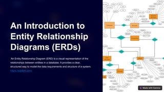
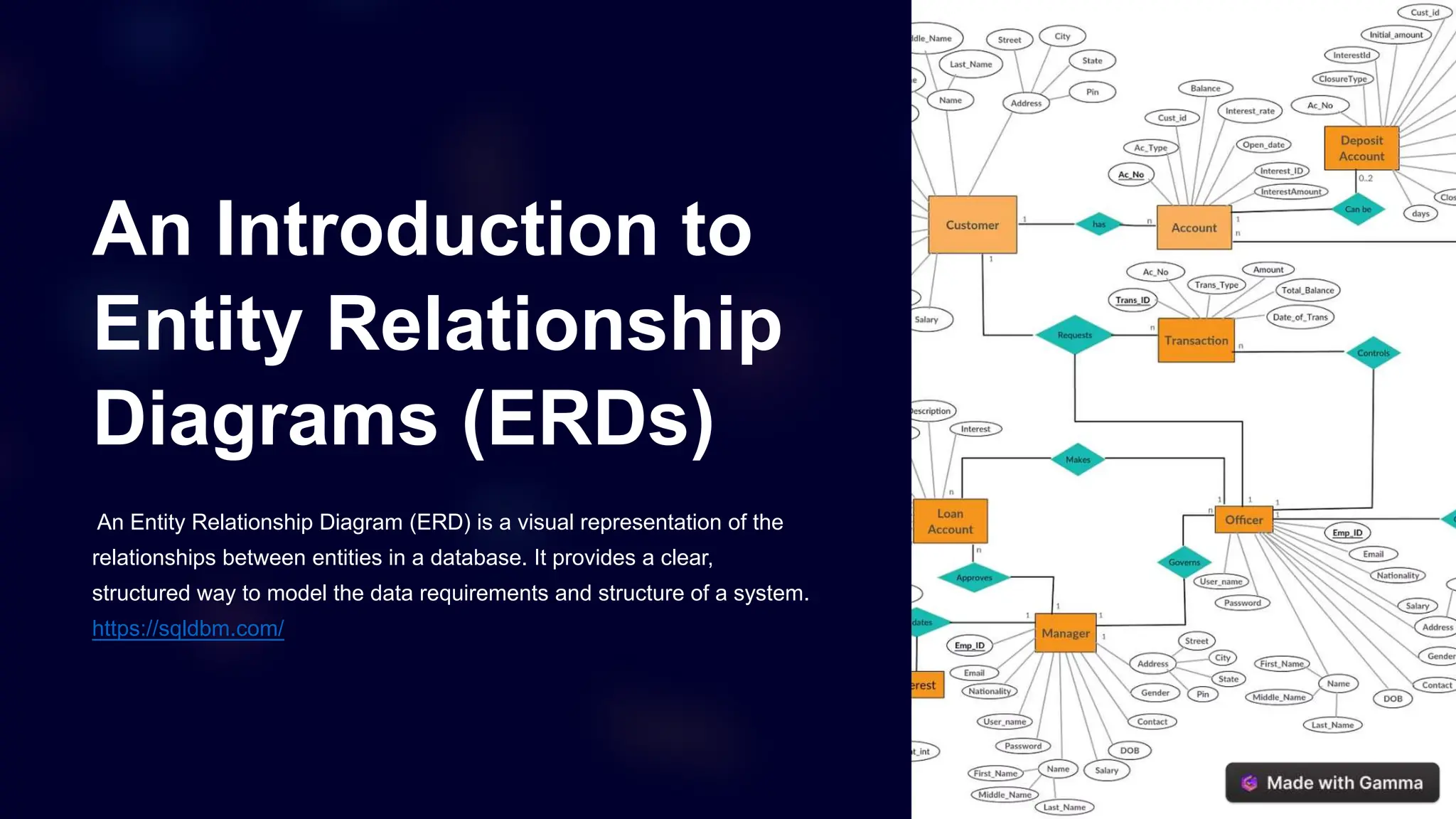
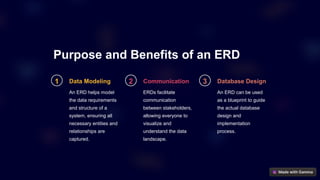
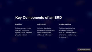


An Entity Relationship Diagram (ERD) visually represents the relationships between entities in a database, aiding in data modeling, communication among stakeholders, and database design. Key components include entities, attributes, and relationships, with various types such as one-to-one and one-to-many. Best practices for creating effective ERDs emphasize clarity, consistency, flexibility, and validation with stakeholders.