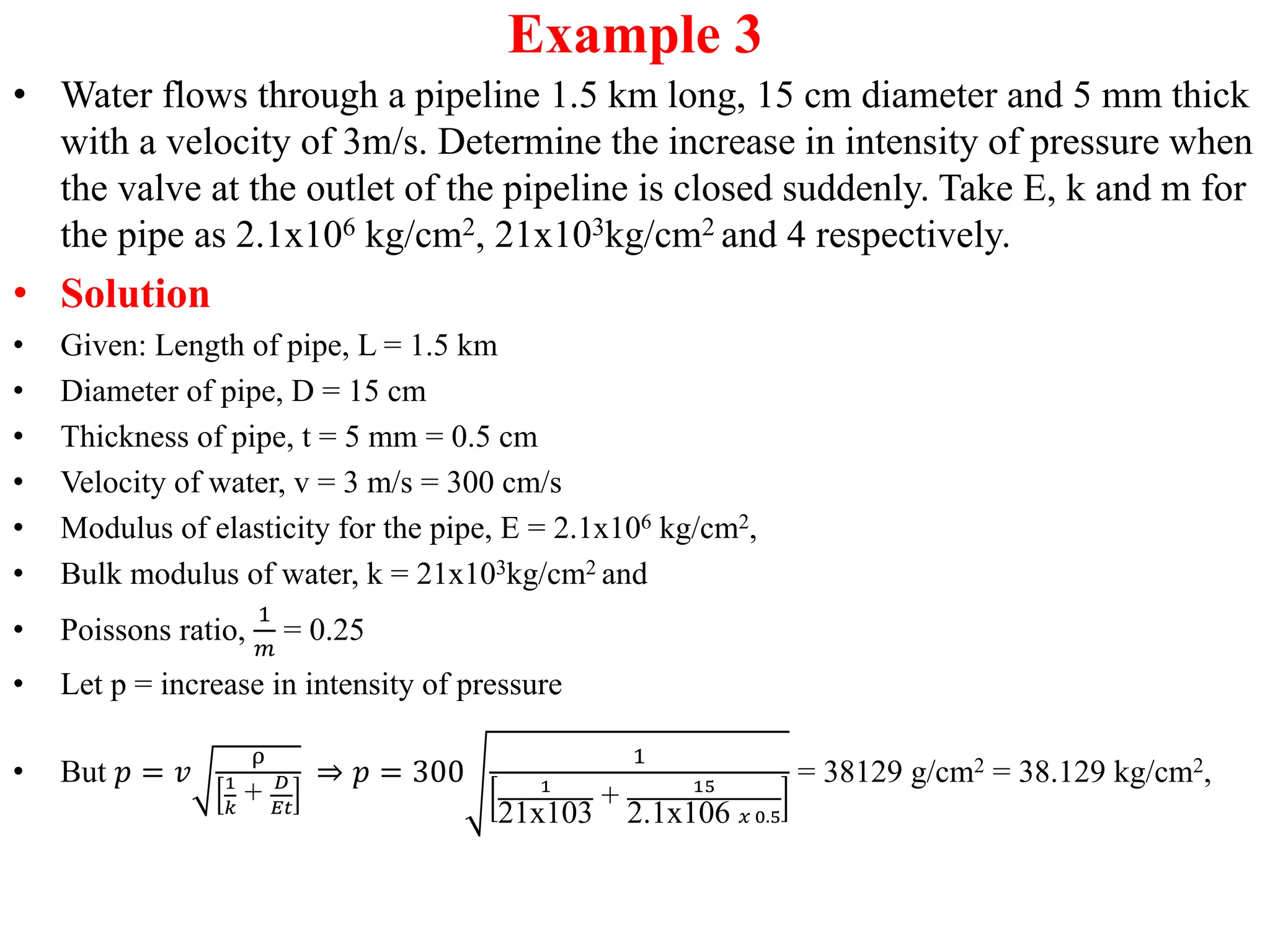
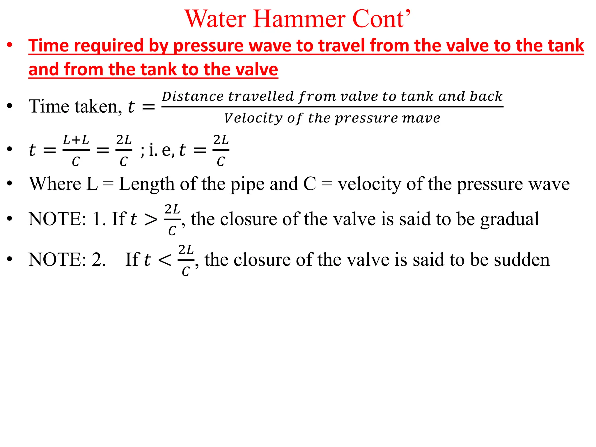
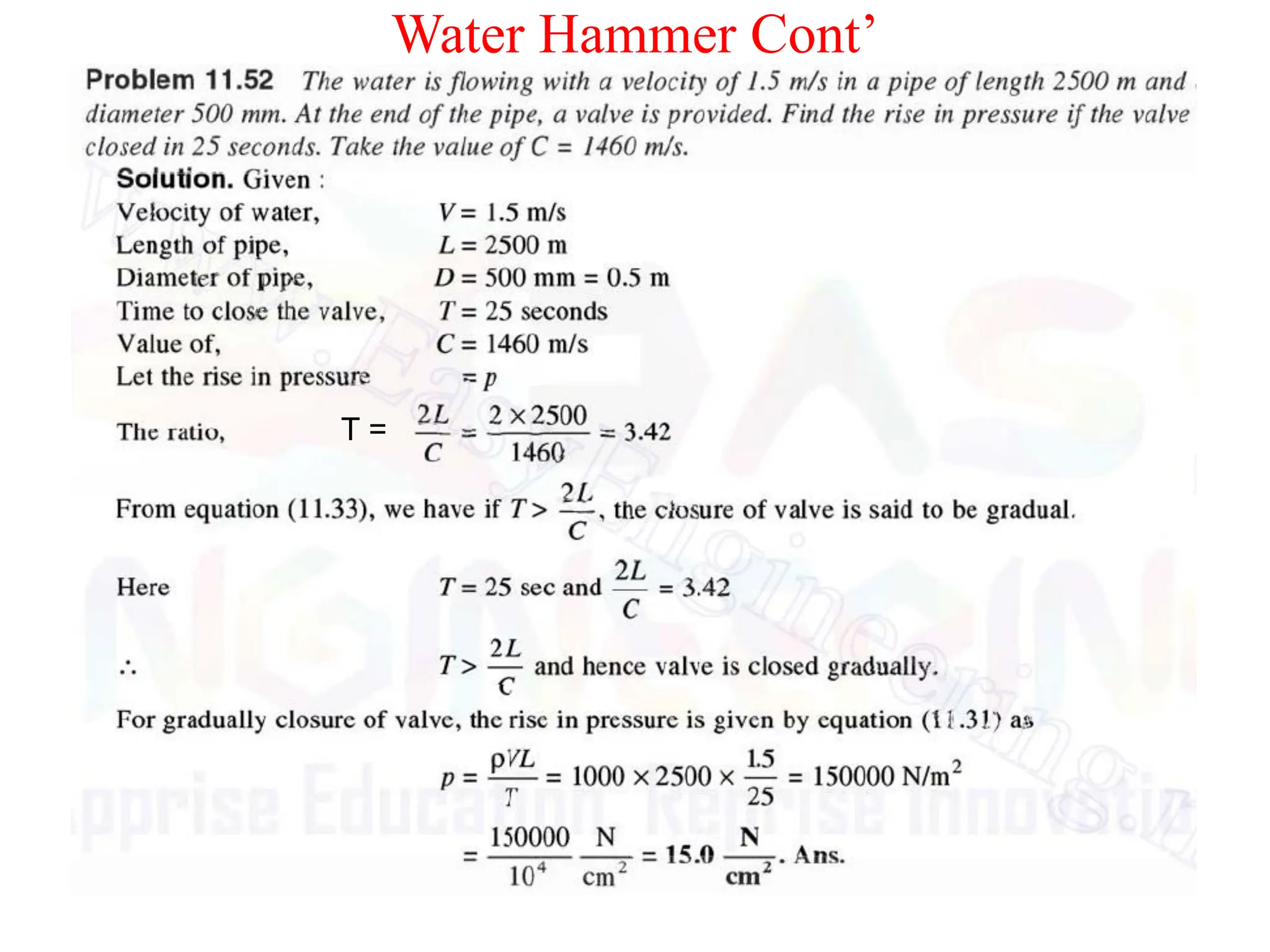
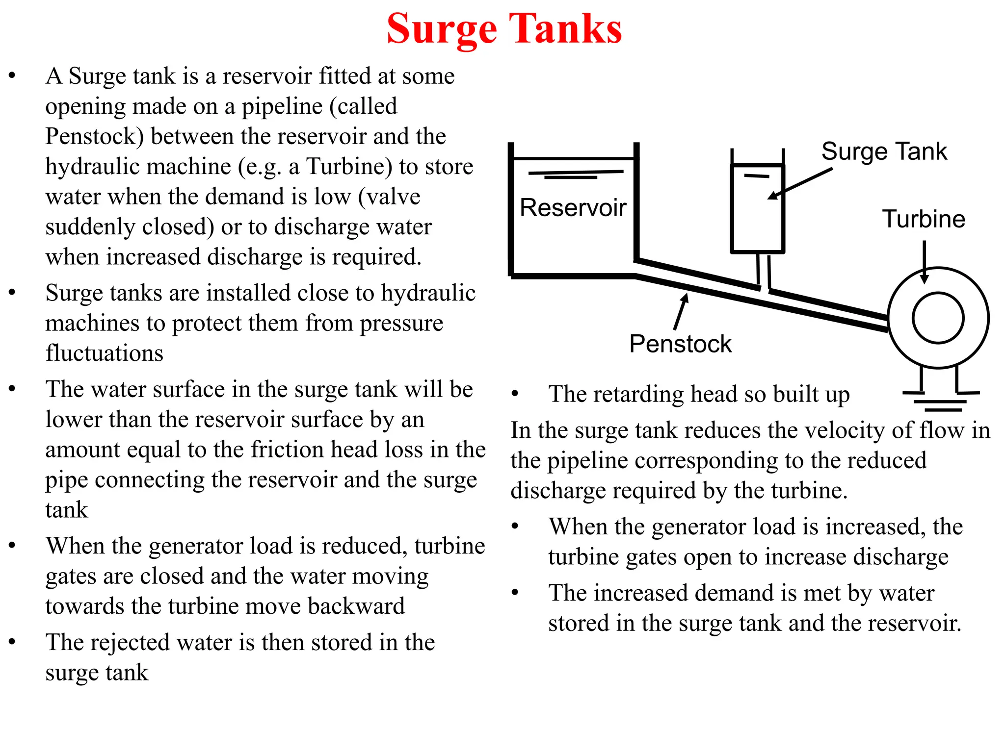
BACHELOR OF SCIENCE IN CIVIL
ENGINEERING
HYDRAULICS II – CCE 2322
Dr. George Okwadha
Water Hammer
• Water flowing in a pipe possesses some momentum due to its motion.
• When the flowing water is suddenly brought to rest by closing the valve, its
velocity is brought to a halt, and its momentum is destroyed.
• This causes a very high pressure on the valve
• The high pressure is followed by a wave of pressure vibrations along the
pipe which sets up or creates noise known as knocking.
• Such a knocking noise is often heard in water pipes if a tap is suddenly
turned off.
• This phenomenon of sudden rise in pressure in the pipe accompanied with
knocking noise is referred to as water hammer or hammer blow.
• This rise in pressure may be so large enough to even cause a pipe burst, and
its essential to take into account this pressure rise in the design of pipes.
• The magnitude of the pressure rise depends on :
– The speed at which the valve is closed
– The velocity of flow
– The length of the pipe
– The elastic properties of the pipe material and the flowing fluid
Water Hammer Cont’
• To reduce the occurrence of water hammer, the valves in a pipeline
should always be closed gradually
• The valve may be closed either gradually or instantaneously, and
according to the nature of the closure of the valve, expressions for
calculating the pressure head due to water hammer may be developed.
(a) Gradual closure of the valve
• Consider a uniform pipeline through which some liquid is flowing with
uniform velocity, and whose valve is closed gradually
• Let L = Length of the pipe
• Let a = cross sectional area of the pipe
• Let v = velocity of water in the pipe
• Let t = Time, in seconds, in which the water is brought to rest by the closure of the
valve
• Let p = increase in intensity of pressure
• Total mass of fluid in the pipe, 𝑚 =
ω𝑎𝐿
𝑔
, where ω is spec. wt. of water and
ω
𝑔
= ρ ...
1
Water Hammer Cont’
• Rate of retardation of the water =
𝑉𝑒𝑙𝑜𝑐𝑖𝑡𝑦
𝑇𝑖𝑚𝑒
=
𝑣
𝑡
……………………
• Force available for causing retardation, F = mass x acceleration
• 𝐹 =
ω𝑎𝐿
𝑔
x
𝑣
𝑡
=
ω𝑎𝐿𝑣
𝑔𝑡
………………………………..
• Intensity of pressure rise in the valve, 𝑝 =
𝐹𝑜𝑟𝑐𝑒
𝐴𝑟𝑒𝑎
=
ω𝑎𝐿𝑣
𝑔𝑡
𝑎
=
ω𝐿𝑣
𝑔𝑡
• Pressure (or inertia) head due to increase in intensity of pressure is
given by: H =
𝑝
ω
=
ω𝐿𝑣
ω𝑔𝑡
=
𝐿𝑣
𝑔𝑡
……………………………….
(b) Instantaneous closure of the valve
• From the previous section, increase in intensity of pressure is given
by: 𝑝 =
ω𝐿𝑣
𝑔𝑡
• If the valve is closed instantly, t = 0, and therefore the increase in
intensity of pressure will be infinite.
2
3
4
Water Hammer Cont’
• But, it is not possible because its not
possible to close the valve
instantaneously, and therefore the
infinite intensity of pressure is
hypothetical
• Consider a uniform pipeline shown
through which some liquid (say water)
is flowing with a uniform velocity and
whose valve is closed suddenly.
• When the valve Is closed suddenly, rise
in intensity of pressure takes place due
to which circumferential stress, σc and
longitudinal stress, σL are produced in
the pipe wall.
t
p
σc
σc
D
σc
σc
σL
σL
L
Water Hammer Cont’
• (a) Circumferential (Hoop) Stress, σc
• This is the stress which is set up to resist the bursting effect of the applied
pressure.
• Let L = Length of the pipe
• p = internal intensity of pressure
• D = Inside diameter of the pipe
• t = thickness of the pipe
• Force tending to push the two halves of the cylinder apart due to internal
intensity of pressure, F = pxDxL -------------------------(1)
• Total resisting force owing to circumferential stress on the cylinder walls,
F = 2x σc x L x t (since σcLt is the force on one wall of the half cylinder) ----(2)
• Equating eqns (1) and (2) gives pxDxL = 2x σc x L x t
𝜎𝑐 =
𝑝𝐷𝐿
2𝐿𝑡
=
𝑝𝐷
2𝑡
Water Hammer Cont’
(b) Longitudinal Stress, σL
• Consider the figure shown.
• Total force due to internal intensity of pressure, p:
F = intensity of pressure x area = px
𝜋𝐷2
4
• Area of the metal resisting this force, A = π.D.t
𝜎𝐿 =
𝐹𝑜𝑟𝑐𝑒
𝐴𝑟𝑒𝑎
=
𝑝𝜋𝐷2
4π𝐷𝑡
=
𝑝𝐷
4𝑡
• Strain Energy stored in the pipe material per unit
volume (From Strength of Materials)
• 𝐺𝑣 =
1
2𝐸
(𝜎𝑐
2
+ 𝜎𝐿
2
−
2𝜎𝑐𝜎𝐿
𝑚
) where
1
𝑚
and E are
poisons ratio and Modulus of elasticity for the pipe
material respectively
• Substituting for 𝜎𝑐 𝑎𝑛𝑑 𝜎𝐿 gives
• 𝐺𝑣 =
1
2𝐸
(
𝑝𝐷
2𝑡
2 +
𝑝𝐷
4𝑡
2
−
2
𝑝𝐷
2𝑡
)(
𝑝𝐷
4𝑡
)
𝑚
)
• 𝐺𝑣 =
1
2𝐸
(
𝑝2𝐷2
4𝑡2 +
𝑝2𝐷2
16𝑡2 −
𝑝2𝐷2
4𝑚𝑡2 ) and if
1
𝑚
=
1
4
then Strain Energy per unit volume is given by
𝐺𝑣 =
1
2𝐸
(
𝑝2𝐷2
4𝑡2 +
𝑝2𝐷2
16𝑡2 −
𝑝2𝐷2
16𝑡2 )
Therefore, 𝐺𝑣 =
𝑝2𝐷2
8𝐸𝑡2.
σL
σL
p p D
t
D
σL acts over the
thickness of the wall, t
Area resisting the force
= π.D.t
Water Hammer Cont’
• Total strain energy stored in the pipe
material is given by
• 𝐺 =
𝑝2𝐷2
8𝐸𝑡2 x total volume of the pipe material
• 𝐺 =
𝑝2𝐷2
8𝐸𝑡2x πDt x L =
𝑝2𝐷3π𝐿
8𝐸𝑡
• 𝐺 =
𝑝2π𝐷2𝐷𝐿
2𝑥4𝐸𝑡
=
𝑝2𝐴𝐷𝐿
2𝐸𝑡
since 𝐴 =
π𝐷2
4
• But loss of kinetic energy of water is given by
KE =
𝑚𝑣2
2
=
ρ𝐴𝐿𝑣2
2
……………………….
• Since m = ρV and V = AL
• Gain in strain energy in water is given by
• 𝐺 =
𝑝2
2𝑘
x Volume (From Strength of
Materials) where k is the bulk modulus of
water Thus 𝐺 =
𝑝2𝐴𝐿
2𝑘
……………………. .
• For a rigid pipeline, Loss of KE of water =
Gain in strain energy in water (ignoring
elasticity of the pipe material)
• Equating eqns 1 and 2 gives
•
ρ𝐴𝐿𝑣2
2
=
𝑝2𝐴𝐿
2𝑘
⇒ 𝑝2 = kρ𝑣2
• 𝑝 = 𝑣 𝑘ρ = 𝑣
𝑘ρ2
ρ
ρ𝑣𝐶 𝑤ℎ𝑒𝑟𝑒 𝐶 =
𝑘
ρ
velocity of pressure wave
• Also, if the elasticity of the pipe material
is considered, then
• Loss of KE of water = Gain in strain
energy in water + strain energy stored in
water.
• Therefore
ρ𝐴𝐿𝑣2
2
=
𝑝2𝐴𝐿
2𝑘
+
𝑝2𝐴𝐷𝐿
2𝐸𝑡
• Dividing both sides by
𝐴𝐿
2
gives
• ρ𝑣2=
𝑝2
𝑘
+
𝑝2𝐷
𝐸𝑡
= 𝑝2 1
𝑘
+
𝐷
𝐸𝑡
• 𝑝 =
ρ𝑣2
1
𝑘
+ 𝐷
𝐸𝑡
= 𝑣
ρ
1
𝑘
+ 𝐷
𝐸𝑡
• NOTE: If the pipeline is considered rigid,
E is infinite, then
𝐷
𝐸𝑡
≈ 0 and the above
equation becomes 𝑝 = 𝑣 𝑘ρ
1
2
Example 1
• Water is supplied to a turbine through a pipe 3 km long. The water flows in the pipe with a
velocity of 2 m/s. A valve near the turbine end is closed in 30 seconds. Find the rise in
intensity of pressure behind the valve in kg/cm2.
• Solution
• Given: Length of pipe, L = 3 km = 3000m
• Velocity of water, v = 3 m/s
• Time of valve closure, t = 30 sec
• Let p = rise in intensity of pressure. But 𝑝 =
ω𝐿𝑣
𝑔𝑡
=
1000𝑥3000𝑥2
9.81𝑥30
= 2.04 kg/cm2
• Example 2
• A valve at the outlet of a rigid pipe is suddenly closed to bring the water to rest. If the
velocity of the water was 3 m/s, find increase in intensity of pressure due to sudden closure
of the valve.
• Solution
• Given: velocity of water, v = 3 m/s; Bulk modulus of water , k = 2.1x10⁴ kg/cm2 = 2.1x10⁸
kg/m2
• Let p = rise in intensity of pressure ⇒𝑝 = 𝑣 𝑘ρ = 𝑣
𝑘ω
𝑔
= 3x
2.1x108 x 1000
9.81
=
43.89x10⁴kg/m2 or 43.89 kg/cm2
Example 3
• Water flows through a pipeline 1.5 km long, 15 cm diameter and 5 mm thick
with a velocity of 3m/s. Determine the increase in intensity of pressure when
the valve at the outlet of the pipeline is closed suddenly. Take E, k and m for
the pipe as 2.1x10⁶ kg/cm2, 21x103kg/cm2 and 4 respectively.
• Solution
• Given: Length of pipe, L = 1.5 km
• Diameter of pipe, D = 15 cm
• Thickness of pipe, t = 5 mm = 0.5 cm
• Velocity of water, v = 3 m/s = 300 cm/s
• Modulus of elasticity for the pipe, E = 2.1x10⁶ kg/cm2,
• Bulk modulus of water, k = 21x103kg/cm2 and
• Poissons ratio,
1
𝑚
= 0.25
• Let p = increase in intensity of pressure
• But 𝑝 = 𝑣
ρ
1
𝑘
+ 𝐷
𝐸𝑡
⇒ 𝑝 = 300
1
1
21x103
+ 15
2.1x10⁶ 𝑥 0.5
= 38129 g/cm2 = 38.129 kg/cm2,
Water Hammer Cont’
• Time required by pressure wave to travel from the valve to the tank
and from the tank to the valve
• Time taken, 𝑡 =
𝐷𝑖𝑠𝑡𝑎𝑛𝑐𝑒 𝑡𝑟𝑎𝑣𝑒𝑙𝑙𝑒𝑑 𝑓𝑟𝑜𝑚 𝑣𝑎𝑙𝑣𝑒 𝑡𝑜 𝑡𝑎𝑛𝑘 𝑎𝑛𝑑 𝑏𝑎𝑐𝑘
𝑉𝑒𝑙𝑜𝑐𝑖𝑡𝑦 𝑜𝑓 𝑡ℎ𝑒 𝑝𝑟𝑒𝑠𝑠𝑢𝑟𝑒 𝑚𝑎𝑣𝑒
• 𝑡 =
𝐿+𝐿
𝐶
=
2𝐿
𝐶
; i. e, 𝑡 =
2𝐿
𝐶
• Where L = Length of the pipe and C = velocity of the pressure wave
• NOTE: 1. If 𝑡 >
2𝐿
𝐶
, the closure of the valve is said to be gradual
• NOTE: 2. If 𝑡 <
2𝐿
𝐶
, the closure of the valve is said to be sudden
Water Hammer Cont’
T =
Surge Tanks
• A Surge tank is a reservoir fitted at some
opening made on a pipeline (called
Penstock) between the reservoir and the
hydraulic machine (e.g. a Turbine) to store
water when the demand is low (valve
suddenly closed) or to discharge water
when increased discharge is required.
• Surge tanks are installed close to hydraulic
machines to protect them from pressure
fluctuations
• The water surface in the surge tank will be
lower than the reservoir surface by an
amount equal to the friction head loss in the
pipe connecting the reservoir and the surge
tank
• When the generator load is reduced, turbine
gates are closed and the water moving
towards the turbine move backward
• The rejected water is then stored in the
surge tank
Reservoir Turbine
Surge Tank
Penstock
• The retarding head so built up
In the surge tank reduces the velocity of flow in
the pipeline corresponding to the reduced
discharge required by the turbine.
• When the generator load is increased, the
turbine gates open to increase discharge
• The increased demand is met by water
stored in the surge tank and the reservoir.
Surge Tanks
• Determination of Fluctuations Depth
in the Surge tank during low and
high load in the turbine
• In the figure shown, a pipeline of area a
conveys water at a velocity, v to the
hydraulic machine (Turbine)
• A Surge tank is located at a distance L from
the reservoir
• The Surge tank’s cross sectional area is A
and
𝐴
𝑎
> 1
• At steady operation condition, the water
level in the tank would be equal to that of
the reservoir if frictional losses are
neglected.
• Let Q1 = Discharge into the Surge tank due
to transient
• Let z = Distance from the steady state water
level to a level caused by a transient
• Let v = Water velocity
• The transient would cause a change in
water level such that 𝑄1 = 𝐴
𝑑𝑧
𝑑𝑡
• But by continuity eqn, av = Q1+Q
• Differentiating with respect to time gives
• 𝑎
𝑑𝑣
𝑑𝑡
=
𝑑𝑄1
𝑑𝑡
+
𝑑𝑄
𝑑𝑡
……………………….
• But the purpose of Surge tank is to reduce
downstream fluctuations. Therefore,
𝑑𝑄
𝑑𝑡
is
negligible compared to other two terms in
eqn. 1. Therefore
• 𝑎
𝑑𝑣
𝑑𝑡
=
𝑑𝑄1
𝑑𝑡
= 𝐴
𝑑2𝑧
𝑑𝑡2……………………
• Acceleration of mass of water due to
transient is given by
𝑑𝑣
𝑑𝑡
Surge Tank
Area, A, Q1
To hydraulic
Machine (Turbi
Q
v
Area, a
Reservoir
Z(t)
L
1
2
Surge Tanks
• Mass of water, m = ρaL
• Note: The resulting inertia is opposed by a
rise z in the liquid level in the Surge tank
• Extra pressure on the Surge tank caused by
the rise z is given by, 𝑝 = ρ𝑔𝑧
• Corresponding opposing force, 𝐹 = 𝜌𝑔𝑧𝑎.
• Force caused by the transient, 𝐹 = 𝑚
𝑑𝑣
𝑑𝑡
…
• Equating eqns 3 and 4 gives
• 𝑚
𝑑𝑣
𝑑𝑡
= -𝜌𝑔𝑧𝑎 ……………………………
• ρaL
𝑑𝑣
𝑑𝑡
= -𝜌𝑔𝑧𝑎 ⇒
𝑑𝑣
𝑑𝑡
= -
𝑔
𝐿
𝑧 … … … … …
• Substituting for
𝑑𝑣
𝑑𝑡
from the continuity eqn.
consideration in eqn. 2 gives
• 𝑎
𝑑𝑣
𝑑𝑡
= 𝐴
𝑑2𝑧
𝑑𝑡2 ⇒ -
𝑔
𝐿
𝑧𝑎 = 𝐴
𝑑2𝑧
𝑑𝑡2
• ⇒
𝑑2𝑧
𝑑𝑡2 +
𝑔
𝐴𝐿
𝑧𝑎 = 0………………………..
• Note: Eqn. 7 is the differential equation
controlling the water level in the Surge
tank, and solving it gives
• 𝑧 = 𝐶1 sin
𝑎𝑔
𝐴𝐿
𝑡 + 𝐶2𝐶𝑜𝑠
𝑎𝑔
𝐴𝐿
t…………
• Since z is measured from the steady water
level in the tank, z = 0 at t = 0 ⇒ 𝐶2=0.
Hence 𝑧 = 𝐶1 sin
𝑎𝑔
𝐴𝐿
𝑡…………
• The constant 𝐶1is evaluated by considering
the situation immediately after a complete
shut down (rejection) to the turbine i.e. at t
= 0 with Q = 0. The entire pipe flow then
enters the Surge tank. Therefore,
• 𝐴
𝑑𝑧
𝑑𝑡 𝑡=0
= 𝑄𝑜 and Differentiating eqn. 9
gives
𝑑𝑧
𝑑𝑡
= 𝐶1
𝑎𝑔
𝐴𝐿
𝐶𝑜𝑠
𝑎𝑔
𝐴𝐿
t
3
4
5
6
7
8
9
Surge Tanks
• Or
𝑑𝑧
𝑑𝑡 𝑡=0
= 𝐶1
𝑎𝑔
𝐴𝐿
. Therefore
•
𝑄𝑜
𝐴
= 𝐶1
𝑎𝑔
𝐴𝐿
…………………………....
• 𝐶1 =
𝑄𝑜
𝐴
𝐴𝐿
𝑎𝑔
• Substituting for 𝐶1 in eqn. 9 gives
• 𝑧 =
𝑄𝑜
𝐴
𝐴𝐿
𝑎𝑔
sin
𝑎𝑔
𝐴𝐿
𝑡…………………
• NOTE: The water level in the Surge tank is
highest when
𝑎𝑔
𝐴𝐿
𝑡 =
π
2
• This yields 𝑧𝑚𝑎𝑥 =
𝑄𝑜
𝐴
𝐴𝐿
𝑎𝑔
• The time period of oscillation is given by
τ = 2π
𝐴𝐿
𝑎𝑔
• Since the water level can fluctuate between
−𝒛𝒎𝒂𝒙 and +𝒛𝒎𝒂𝒙 measured from the
steady water level, the height of the Surge
tank should be greater than 2𝒛𝒎𝒂𝒙.
• Similarly, the minimum water level should
be greater than 𝒛𝒎𝒂𝒙 so that the water under
oscillation does not drop to the opening of
the pipe which would then cause an airlock.
10
11
π
2
1
-1
The Sine wave
π 3π
2
2π
Surge tank
• Example
• Water to a Pelton wheel (A pelton wheel is the rotating part of an impulse turbine) is supplied
through a 1.5km long pipeline 1m in dia. at the rate of 3m3/s. A 2.5m dia. Surge tank is
installed close to the turbine for protection against transients caused by a nozzle movement.
Consider a condition of full rejection i.e when the pipe discharge end is fully closed suddenly.
Estimate the consequent time period of oscillation of the water column in the Surge tank, and
the time required to reach the maximum fluctuation from the instant the discharge is stopped.
• Solution
• Pipe area, 𝑎 =
𝜋
4
12
= 0.7854m2
• Surge tank area, 𝐴 =
𝜋
4
2.52
= 4.9087m2
• 𝑣 =
𝑄𝑜
𝐴
=
3
4.9087
= 0.611 m/s
•
𝐴𝐿
𝑎𝑔
=
4.9087𝑥1.5𝑥103
0.7854𝑥9.81
= 30.91s
• 𝑧𝑚𝑎𝑥 =
𝑄𝑜
𝐴
𝐴𝐿
𝑎𝑔
= 0.611x 30.91 = 18.89m
• Time period, τ = 2π
𝐴𝐿
𝑎𝑔
= 2π𝑥30.91 = 194.21𝑠
• The maximum amplitude occurs at
τ
4
=
194.21
4
= 48.55s from the onset of rejection

Engineering Hydraulics II slides 36-51.pdf

  • 1.
    BACHELOR OF SCIENCEIN CIVIL ENGINEERING HYDRAULICS II – CCE 2322 Dr. George Okwadha
  • 2.
    Water Hammer • Waterflowing in a pipe possesses some momentum due to its motion. • When the flowing water is suddenly brought to rest by closing the valve, its velocity is brought to a halt, and its momentum is destroyed. • This causes a very high pressure on the valve • The high pressure is followed by a wave of pressure vibrations along the pipe which sets up or creates noise known as knocking. • Such a knocking noise is often heard in water pipes if a tap is suddenly turned off. • This phenomenon of sudden rise in pressure in the pipe accompanied with knocking noise is referred to as water hammer or hammer blow. • This rise in pressure may be so large enough to even cause a pipe burst, and its essential to take into account this pressure rise in the design of pipes. • The magnitude of the pressure rise depends on : – The speed at which the valve is closed – The velocity of flow – The length of the pipe – The elastic properties of the pipe material and the flowing fluid
  • 3.
    Water Hammer Cont’ •To reduce the occurrence of water hammer, the valves in a pipeline should always be closed gradually • The valve may be closed either gradually or instantaneously, and according to the nature of the closure of the valve, expressions for calculating the pressure head due to water hammer may be developed. (a) Gradual closure of the valve • Consider a uniform pipeline through which some liquid is flowing with uniform velocity, and whose valve is closed gradually • Let L = Length of the pipe • Let a = cross sectional area of the pipe • Let v = velocity of water in the pipe • Let t = Time, in seconds, in which the water is brought to rest by the closure of the valve • Let p = increase in intensity of pressure • Total mass of fluid in the pipe, 𝑚 = ω𝑎𝐿 𝑔 , where ω is spec. wt. of water and ω 𝑔 = ρ ... 1
  • 4.
    Water Hammer Cont’ •Rate of retardation of the water = 𝑉𝑒𝑙𝑜𝑐𝑖𝑡𝑦 𝑇𝑖𝑚𝑒 = 𝑣 𝑡 …………………… • Force available for causing retardation, F = mass x acceleration • 𝐹 = ω𝑎𝐿 𝑔 x 𝑣 𝑡 = ω𝑎𝐿𝑣 𝑔𝑡 ……………………………….. • Intensity of pressure rise in the valve, 𝑝 = 𝐹𝑜𝑟𝑐𝑒 𝐴𝑟𝑒𝑎 = ω𝑎𝐿𝑣 𝑔𝑡 𝑎 = ω𝐿𝑣 𝑔𝑡 • Pressure (or inertia) head due to increase in intensity of pressure is given by: H = 𝑝 ω = ω𝐿𝑣 ω𝑔𝑡 = 𝐿𝑣 𝑔𝑡 ………………………………. (b) Instantaneous closure of the valve • From the previous section, increase in intensity of pressure is given by: 𝑝 = ω𝐿𝑣 𝑔𝑡 • If the valve is closed instantly, t = 0, and therefore the increase in intensity of pressure will be infinite. 2 3 4
  • 5.
    Water Hammer Cont’ •But, it is not possible because its not possible to close the valve instantaneously, and therefore the infinite intensity of pressure is hypothetical • Consider a uniform pipeline shown through which some liquid (say water) is flowing with a uniform velocity and whose valve is closed suddenly. • When the valve Is closed suddenly, rise in intensity of pressure takes place due to which circumferential stress, σc and longitudinal stress, σL are produced in the pipe wall. t p σc σc D σc σc σL σL L
  • 6.
    Water Hammer Cont’ •(a) Circumferential (Hoop) Stress, σc • This is the stress which is set up to resist the bursting effect of the applied pressure. • Let L = Length of the pipe • p = internal intensity of pressure • D = Inside diameter of the pipe • t = thickness of the pipe • Force tending to push the two halves of the cylinder apart due to internal intensity of pressure, F = pxDxL -------------------------(1) • Total resisting force owing to circumferential stress on the cylinder walls, F = 2x σc x L x t (since σcLt is the force on one wall of the half cylinder) ----(2) • Equating eqns (1) and (2) gives pxDxL = 2x σc x L x t 𝜎𝑐 = 𝑝𝐷𝐿 2𝐿𝑡 = 𝑝𝐷 2𝑡
  • 7.
    Water Hammer Cont’ (b)Longitudinal Stress, σL • Consider the figure shown. • Total force due to internal intensity of pressure, p: F = intensity of pressure x area = px 𝜋𝐷2 4 • Area of the metal resisting this force, A = π.D.t 𝜎𝐿 = 𝐹𝑜𝑟𝑐𝑒 𝐴𝑟𝑒𝑎 = 𝑝𝜋𝐷2 4π𝐷𝑡 = 𝑝𝐷 4𝑡 • Strain Energy stored in the pipe material per unit volume (From Strength of Materials) • 𝐺𝑣 = 1 2𝐸 (𝜎𝑐 2 + 𝜎𝐿 2 − 2𝜎𝑐𝜎𝐿 𝑚 ) where 1 𝑚 and E are poisons ratio and Modulus of elasticity for the pipe material respectively • Substituting for 𝜎𝑐 𝑎𝑛𝑑 𝜎𝐿 gives • 𝐺𝑣 = 1 2𝐸 ( 𝑝𝐷 2𝑡 2 + 𝑝𝐷 4𝑡 2 − 2 𝑝𝐷 2𝑡 )( 𝑝𝐷 4𝑡 ) 𝑚 ) • 𝐺𝑣 = 1 2𝐸 ( 𝑝2𝐷2 4𝑡2 + 𝑝2𝐷2 16𝑡2 − 𝑝2𝐷2 4𝑚𝑡2 ) and if 1 𝑚 = 1 4 then Strain Energy per unit volume is given by 𝐺𝑣 = 1 2𝐸 ( 𝑝2𝐷2 4𝑡2 + 𝑝2𝐷2 16𝑡2 − 𝑝2𝐷2 16𝑡2 ) Therefore, 𝐺𝑣 = 𝑝2𝐷2 8𝐸𝑡2. σL σL p p D t D σL acts over the thickness of the wall, t Area resisting the force = π.D.t
  • 8.
    Water Hammer Cont’ •Total strain energy stored in the pipe material is given by • 𝐺 = 𝑝2𝐷2 8𝐸𝑡2 x total volume of the pipe material • 𝐺 = 𝑝2𝐷2 8𝐸𝑡2x πDt x L = 𝑝2𝐷3π𝐿 8𝐸𝑡 • 𝐺 = 𝑝2π𝐷2𝐷𝐿 2𝑥4𝐸𝑡 = 𝑝2𝐴𝐷𝐿 2𝐸𝑡 since 𝐴 = π𝐷2 4 • But loss of kinetic energy of water is given by KE = 𝑚𝑣2 2 = ρ𝐴𝐿𝑣2 2 ………………………. • Since m = ρV and V = AL • Gain in strain energy in water is given by • 𝐺 = 𝑝2 2𝑘 x Volume (From Strength of Materials) where k is the bulk modulus of water Thus 𝐺 = 𝑝2𝐴𝐿 2𝑘 ……………………. . • For a rigid pipeline, Loss of KE of water = Gain in strain energy in water (ignoring elasticity of the pipe material) • Equating eqns 1 and 2 gives • ρ𝐴𝐿𝑣2 2 = 𝑝2𝐴𝐿 2𝑘 ⇒ 𝑝2 = kρ𝑣2 • 𝑝 = 𝑣 𝑘ρ = 𝑣 𝑘ρ2 ρ ρ𝑣𝐶 𝑤ℎ𝑒𝑟𝑒 𝐶 = 𝑘 ρ velocity of pressure wave • Also, if the elasticity of the pipe material is considered, then • Loss of KE of water = Gain in strain energy in water + strain energy stored in water. • Therefore ρ𝐴𝐿𝑣2 2 = 𝑝2𝐴𝐿 2𝑘 + 𝑝2𝐴𝐷𝐿 2𝐸𝑡 • Dividing both sides by 𝐴𝐿 2 gives • ρ𝑣2= 𝑝2 𝑘 + 𝑝2𝐷 𝐸𝑡 = 𝑝2 1 𝑘 + 𝐷 𝐸𝑡 • 𝑝 = ρ𝑣2 1 𝑘 + 𝐷 𝐸𝑡 = 𝑣 ρ 1 𝑘 + 𝐷 𝐸𝑡 • NOTE: If the pipeline is considered rigid, E is infinite, then 𝐷 𝐸𝑡 ≈ 0 and the above equation becomes 𝑝 = 𝑣 𝑘ρ 1 2
  • 9.
    Example 1 • Wateris supplied to a turbine through a pipe 3 km long. The water flows in the pipe with a velocity of 2 m/s. A valve near the turbine end is closed in 30 seconds. Find the rise in intensity of pressure behind the valve in kg/cm2. • Solution • Given: Length of pipe, L = 3 km = 3000m • Velocity of water, v = 3 m/s • Time of valve closure, t = 30 sec • Let p = rise in intensity of pressure. But 𝑝 = ω𝐿𝑣 𝑔𝑡 = 1000𝑥3000𝑥2 9.81𝑥30 = 2.04 kg/cm2 • Example 2 • A valve at the outlet of a rigid pipe is suddenly closed to bring the water to rest. If the velocity of the water was 3 m/s, find increase in intensity of pressure due to sudden closure of the valve. • Solution • Given: velocity of water, v = 3 m/s; Bulk modulus of water , k = 2.1x10⁴ kg/cm2 = 2.1x10⁸ kg/m2 • Let p = rise in intensity of pressure ⇒𝑝 = 𝑣 𝑘ρ = 𝑣 𝑘ω 𝑔 = 3x 2.1x108 x 1000 9.81 = 43.89x10⁴kg/m2 or 43.89 kg/cm2
  • 10.
    Example 3 • Waterflows through a pipeline 1.5 km long, 15 cm diameter and 5 mm thick with a velocity of 3m/s. Determine the increase in intensity of pressure when the valve at the outlet of the pipeline is closed suddenly. Take E, k and m for the pipe as 2.1x10⁶ kg/cm2, 21x103kg/cm2 and 4 respectively. • Solution • Given: Length of pipe, L = 1.5 km • Diameter of pipe, D = 15 cm • Thickness of pipe, t = 5 mm = 0.5 cm • Velocity of water, v = 3 m/s = 300 cm/s • Modulus of elasticity for the pipe, E = 2.1x10⁶ kg/cm2, • Bulk modulus of water, k = 21x103kg/cm2 and • Poissons ratio, 1 𝑚 = 0.25 • Let p = increase in intensity of pressure • But 𝑝 = 𝑣 ρ 1 𝑘 + 𝐷 𝐸𝑡 ⇒ 𝑝 = 300 1 1 21x103 + 15 2.1x10⁶ 𝑥 0.5 = 38129 g/cm2 = 38.129 kg/cm2,
  • 11.
    Water Hammer Cont’ •Time required by pressure wave to travel from the valve to the tank and from the tank to the valve • Time taken, 𝑡 = 𝐷𝑖𝑠𝑡𝑎𝑛𝑐𝑒 𝑡𝑟𝑎𝑣𝑒𝑙𝑙𝑒𝑑 𝑓𝑟𝑜𝑚 𝑣𝑎𝑙𝑣𝑒 𝑡𝑜 𝑡𝑎𝑛𝑘 𝑎𝑛𝑑 𝑏𝑎𝑐𝑘 𝑉𝑒𝑙𝑜𝑐𝑖𝑡𝑦 𝑜𝑓 𝑡ℎ𝑒 𝑝𝑟𝑒𝑠𝑠𝑢𝑟𝑒 𝑚𝑎𝑣𝑒 • 𝑡 = 𝐿+𝐿 𝐶 = 2𝐿 𝐶 ; i. e, 𝑡 = 2𝐿 𝐶 • Where L = Length of the pipe and C = velocity of the pressure wave • NOTE: 1. If 𝑡 > 2𝐿 𝐶 , the closure of the valve is said to be gradual • NOTE: 2. If 𝑡 < 2𝐿 𝐶 , the closure of the valve is said to be sudden
  • 12.
  • 13.
    Surge Tanks • ASurge tank is a reservoir fitted at some opening made on a pipeline (called Penstock) between the reservoir and the hydraulic machine (e.g. a Turbine) to store water when the demand is low (valve suddenly closed) or to discharge water when increased discharge is required. • Surge tanks are installed close to hydraulic machines to protect them from pressure fluctuations • The water surface in the surge tank will be lower than the reservoir surface by an amount equal to the friction head loss in the pipe connecting the reservoir and the surge tank • When the generator load is reduced, turbine gates are closed and the water moving towards the turbine move backward • The rejected water is then stored in the surge tank Reservoir Turbine Surge Tank Penstock • The retarding head so built up In the surge tank reduces the velocity of flow in the pipeline corresponding to the reduced discharge required by the turbine. • When the generator load is increased, the turbine gates open to increase discharge • The increased demand is met by water stored in the surge tank and the reservoir.
  • 14.
    Surge Tanks • Determinationof Fluctuations Depth in the Surge tank during low and high load in the turbine • In the figure shown, a pipeline of area a conveys water at a velocity, v to the hydraulic machine (Turbine) • A Surge tank is located at a distance L from the reservoir • The Surge tank’s cross sectional area is A and 𝐴 𝑎 > 1 • At steady operation condition, the water level in the tank would be equal to that of the reservoir if frictional losses are neglected. • Let Q1 = Discharge into the Surge tank due to transient • Let z = Distance from the steady state water level to a level caused by a transient • Let v = Water velocity • The transient would cause a change in water level such that 𝑄1 = 𝐴 𝑑𝑧 𝑑𝑡 • But by continuity eqn, av = Q1+Q • Differentiating with respect to time gives • 𝑎 𝑑𝑣 𝑑𝑡 = 𝑑𝑄1 𝑑𝑡 + 𝑑𝑄 𝑑𝑡 ………………………. • But the purpose of Surge tank is to reduce downstream fluctuations. Therefore, 𝑑𝑄 𝑑𝑡 is negligible compared to other two terms in eqn. 1. Therefore • 𝑎 𝑑𝑣 𝑑𝑡 = 𝑑𝑄1 𝑑𝑡 = 𝐴 𝑑2𝑧 𝑑𝑡2…………………… • Acceleration of mass of water due to transient is given by 𝑑𝑣 𝑑𝑡 Surge Tank Area, A, Q1 To hydraulic Machine (Turbi Q v Area, a Reservoir Z(t) L 1 2
  • 15.
    Surge Tanks • Massof water, m = ρaL • Note: The resulting inertia is opposed by a rise z in the liquid level in the Surge tank • Extra pressure on the Surge tank caused by the rise z is given by, 𝑝 = ρ𝑔𝑧 • Corresponding opposing force, 𝐹 = 𝜌𝑔𝑧𝑎. • Force caused by the transient, 𝐹 = 𝑚 𝑑𝑣 𝑑𝑡 … • Equating eqns 3 and 4 gives • 𝑚 𝑑𝑣 𝑑𝑡 = -𝜌𝑔𝑧𝑎 …………………………… • ρaL 𝑑𝑣 𝑑𝑡 = -𝜌𝑔𝑧𝑎 ⇒ 𝑑𝑣 𝑑𝑡 = - 𝑔 𝐿 𝑧 … … … … … • Substituting for 𝑑𝑣 𝑑𝑡 from the continuity eqn. consideration in eqn. 2 gives • 𝑎 𝑑𝑣 𝑑𝑡 = 𝐴 𝑑2𝑧 𝑑𝑡2 ⇒ - 𝑔 𝐿 𝑧𝑎 = 𝐴 𝑑2𝑧 𝑑𝑡2 • ⇒ 𝑑2𝑧 𝑑𝑡2 + 𝑔 𝐴𝐿 𝑧𝑎 = 0……………………….. • Note: Eqn. 7 is the differential equation controlling the water level in the Surge tank, and solving it gives • 𝑧 = 𝐶1 sin 𝑎𝑔 𝐴𝐿 𝑡 + 𝐶2𝐶𝑜𝑠 𝑎𝑔 𝐴𝐿 t………… • Since z is measured from the steady water level in the tank, z = 0 at t = 0 ⇒ 𝐶2=0. Hence 𝑧 = 𝐶1 sin 𝑎𝑔 𝐴𝐿 𝑡………… • The constant 𝐶1is evaluated by considering the situation immediately after a complete shut down (rejection) to the turbine i.e. at t = 0 with Q = 0. The entire pipe flow then enters the Surge tank. Therefore, • 𝐴 𝑑𝑧 𝑑𝑡 𝑡=0 = 𝑄𝑜 and Differentiating eqn. 9 gives 𝑑𝑧 𝑑𝑡 = 𝐶1 𝑎𝑔 𝐴𝐿 𝐶𝑜𝑠 𝑎𝑔 𝐴𝐿 t 3 4 5 6 7 8 9
  • 16.
    Surge Tanks • Or 𝑑𝑧 𝑑𝑡𝑡=0 = 𝐶1 𝑎𝑔 𝐴𝐿 . Therefore • 𝑄𝑜 𝐴 = 𝐶1 𝑎𝑔 𝐴𝐿 ………………………….... • 𝐶1 = 𝑄𝑜 𝐴 𝐴𝐿 𝑎𝑔 • Substituting for 𝐶1 in eqn. 9 gives • 𝑧 = 𝑄𝑜 𝐴 𝐴𝐿 𝑎𝑔 sin 𝑎𝑔 𝐴𝐿 𝑡………………… • NOTE: The water level in the Surge tank is highest when 𝑎𝑔 𝐴𝐿 𝑡 = π 2 • This yields 𝑧𝑚𝑎𝑥 = 𝑄𝑜 𝐴 𝐴𝐿 𝑎𝑔 • The time period of oscillation is given by τ = 2π 𝐴𝐿 𝑎𝑔 • Since the water level can fluctuate between −𝒛𝒎𝒂𝒙 and +𝒛𝒎𝒂𝒙 measured from the steady water level, the height of the Surge tank should be greater than 2𝒛𝒎𝒂𝒙. • Similarly, the minimum water level should be greater than 𝒛𝒎𝒂𝒙 so that the water under oscillation does not drop to the opening of the pipe which would then cause an airlock. 10 11 π 2 1 -1 The Sine wave π 3π 2 2π
  • 17.
    Surge tank • Example •Water to a Pelton wheel (A pelton wheel is the rotating part of an impulse turbine) is supplied through a 1.5km long pipeline 1m in dia. at the rate of 3m3/s. A 2.5m dia. Surge tank is installed close to the turbine for protection against transients caused by a nozzle movement. Consider a condition of full rejection i.e when the pipe discharge end is fully closed suddenly. Estimate the consequent time period of oscillation of the water column in the Surge tank, and the time required to reach the maximum fluctuation from the instant the discharge is stopped. • Solution • Pipe area, 𝑎 = 𝜋 4 12 = 0.7854m2 • Surge tank area, 𝐴 = 𝜋 4 2.52 = 4.9087m2 • 𝑣 = 𝑄𝑜 𝐴 = 3 4.9087 = 0.611 m/s • 𝐴𝐿 𝑎𝑔 = 4.9087𝑥1.5𝑥103 0.7854𝑥9.81 = 30.91s • 𝑧𝑚𝑎𝑥 = 𝑄𝑜 𝐴 𝐴𝐿 𝑎𝑔 = 0.611x 30.91 = 18.89m • Time period, τ = 2π 𝐴𝐿 𝑎𝑔 = 2π𝑥30.91 = 194.21𝑠 • The maximum amplitude occurs at τ 4 = 194.21 4 = 48.55s from the onset of rejection