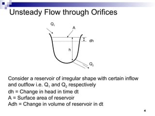
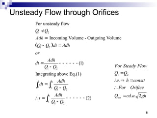
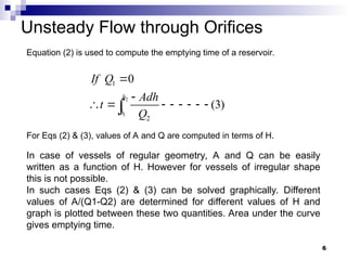
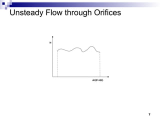
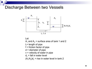
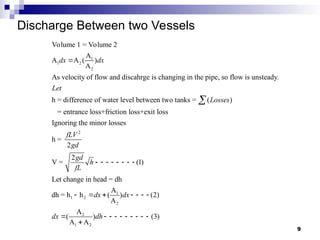
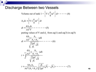
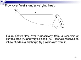
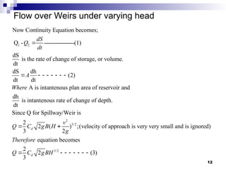
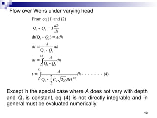
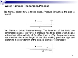
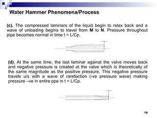
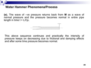
Unsteady Flow
1
Unsteady Flow
 Conditions of flow don not remain constant w.r.t.
time at a particular section. i.e.
0
0
0
dy
dt
dv
dt
dQ
dt



2
Examples of Unsteady Flow
 Discharge through orifices and over weirs under
varying heads.
 Unsteady Flow through pipe lines due to
opening and closing of valves, Water hammer
due to sudden closure of valves.
 Surge wave in open channels.
3
Unsteady Flow through Orifices
Q1
Q2
h
dh
A
Consider a reservoir of irregular shape with certain inflow
and outflow i.e. Q1 and Q2 respectively
dh = Change in head in time dt
A = Surface area of reservoir
Adh = Change in volume of reservoir in dt
4
Unsteady Flow through Orifices
 
2
1
2
1
1 2
1 2
1 2
0
1 2
1 2
For unsteady flow
Incoming Volume - Outgoing Volume
(1)
Integrating above Eq.(1)
(2)
t h
h
h
h
Q Q
Adh
Q Q dt Adh
or
Adh
dt
Q Q
Adh
dt
Q Q
Adh
t
Q Q


 
      



       

 

1 2
. .
. . 2
act
For Steady Flow
Q Q
i e h constt
For Orifice
Q cd a gh

 


5
Unsteady Flow through Orifices
2
1
1
2
0
(3)
h
h
If Q
Adh
t
Q


       

Equation (2) is used to compute the emptying time of a reservoir.
For Eqs (2) & (3), values of A and Q are computed in terms of H.
In case of vessels of regular geometry, A and Q can be easily
written as a function of H. However for vessels of irregular shape
this is not possible.
In such cases Eqs (2) & (3) can be solved graphically. Different
values of A/(Q1-Q2) are determined for different values of H and
graph is plotted between these two quantities. Area under the curve
gives emptying time.
6
Unsteady Flow through Orifices
H
A/(Q1-Q2)
7
Discharge Between two Vessels
Let
A1 and A2 = surface area of tank 1 and 2
L= length of pipe
f = friction factor of pipe
d = diameter of pipe
v = velocity of water in pipe
dx = fall in water level
(A1/A2)dx = rise in water level in tank 2
A2
(A1/A2)dx
h1
A1
h2
V
L, f, d
dx
8
Discharge Between two Vessels
1
1 2
2
Volume 1 = Volume 2
A
A A ( )
A
As velocity of flow and discahrge is changing in the pipe, so flow is unsteady.
h = difference of water level between two tanks = ( )
= entrance loss+fricti
dx dx
Let
Losses


2
1
1 2
2
2
1 2
on loss+exit loss
Ignoring the minor losses
h =
2
2
V = (1)
Let change in head = dh
A
dh = h h ( ) (2)
A
A
( ) (3)
A A
fLV
gd
gd
h
fL
dx dx
dx dh
       
      
         

9
Discharge Between two Vessels
2
2
1
1
2
x
1 2
2
1 2
1 2
2
1 2
Volume out of tank 1 = V ( ) (4)
4
A V ( )
4
4A
(5)
putting values of V and d from eq(1) and eq(3) in eq(5)
4A A
( )
A +A
(6)
2
4A A
( )
A +A
d dt
dx d dt
dx
dt
d V
dh
d
dt
gd
h
fL
d
d
t





 
    
 
 
 
 
 
        
      

2
1
1 2
1 2
2
1 2
2
8A A
( ) (7)
(A +A ) 2
h
h
h
gd
h
fL
fL
t h h
d gd

        

10
Flow over Weirs under varying head
Figure shows flow over weir/spillway from a reservoir of
surface area (A) and varying head (h). Reservoir receives an
inflow Q1 while a discharge Q2 is withdrawn from it.
h
Q1
A
Q2
11
Flow over Weirs under varying head
1 2
Now Continuity Equation becomes;
Q - ----------------(1)
dS
is the rate of change of storage, or volume.
dt
dS dh
(2)
dt dt
A is intantenous plan area of reservoir and
dh
is intantenous
dt
dS
Q
dt
A
Where

       
2
3/2
3/2
rate of change of depth.
Since Q for Spillway/Weir is
2
2 ( ) ;(velocity of approach is very very small and is ignored)
3 2
equation becomes
2
2 (3)
3
d
d
v
Q C gB H
g
Therefore
Q C gBH
 
       
12
Flow over Weirs under varying head
1 2
1 2
1 2
2
1 2
1
2
3/2
1
1
From eq (1) and (2)
Q
dt(Q )
Q
Q
(4)
2
Q 2
3
h
h
h
h
d
dh
Q A
dt
Q Adh
A
dt dh
Q
A
dt dh
Q
A
t dh
C gBH
 
 




       



Except in the special case where A does not vary with depth
and Q1 is constant, eq (4) is not directly integrable and in
general must be evaluated numerically.
13
Question
 A Reservoir of water surface area 900,000 m2
is provided with a
spillway 30m long which may be treated as rectangular notch with
Cd=0.72
 Find the time in hours for head over the spillway to fall from 0.6m
to 0.15m. Neglect inflow.
14
Water Hammer (Hammer Blow)
 Whenever velocity in a pipe line is reduced instantaneously or in a
very short time a sudden increase in pressure takes place. This
sudden rise in pressure in a pipe line due to stoppage of flow is known
as water hammer or hammer blow.
 The increase in pressure is so high that the pipe may burst if it is not
strong enough to withstand that pressure.
 Water hammer is used for all type of fluids, its not specific for water.
V
L
15
The water hammer pressure is due to the inertial head which is given by Newton's equation
let v be brought to zero in time "t".
(1)
" " is time in which valve is closed
Pressur
i
i
F ma
v
Pa aL
t
Lv
P
gt
t




       
e head = hi = (2)
head due to water hammer
if t = 0 in closing the valve
and
i
i
i i
P Lv
gt
h
Lv
P h
gt


        

  
Assumptions:
(i)t = 0
(ii)Water is incompressible
(iii)Pipe material is rigid
The pressure and pressure head given by eq (1) and (2) do not approach to
infinity practically because:
(i)It is difficult to close valve in zero time
(ii)Water behaves as compressible fluid at higher pressure
(iii)Material of pipe behave elastically up to certain limits 16
Water Hammer Pressure Diagram
V
L
Ph/ᵧ
P/ᵧ
x
(L-x)
M B N
2
2
L
v
h
g

Cp
17
Water Hammer Phenomena/Process
(a). Normal steady flow is taking place. Pressure throughout the pipe is
normal
(b). Valve is closed instantaneously. The laminars of the liquid are
compressed against the valve, a pressure rise takes place which begins
to travel u/s with a velocity of Cp. After time t = L/Cp, the pressure wave
has travelled the entire length of the pipe making pressure high and
stretching the entire length of the pipe, its diameter is increased.
V
L
V
Cp
18
Water Hammer Phenomena/Process
(c). The compressed laminars of the liquid begin to relax back and a
wave of unloading begins to travel from M to N. Pressure throughout
pipe becomes normal in time t = L/Cp.
(d). At the same time, the last laminar against the valve moves back
and negative pressure is created at the valve which is theoretically of
the same magnitude as the positive pressure. This negative pressure
travels u/s with a wave of rarefaction (-ve pressure wave) making
pressure –ve in entire ppe in t = L/Cp.
19
Water Hammer Phenomena/Process
(e). The wave of –ve pressure returns back from M as a wave of
normal pressure and the pressure becomes normal in entire pipe
length in time t = L/Cp.
This above sequence continues and practically the intensity of
pressure keeps on decreasing due to frictional and damping effects
and after some time pressure becomes normal.
20

14.-Unsteady-Flow.ppt lecture civil engineering

  • 1.
  • 2.
    Unsteady Flow  Conditionsof flow don not remain constant w.r.t. time at a particular section. i.e. 0 0 0 dy dt dv dt dQ dt    2
  • 3.
    Examples of UnsteadyFlow  Discharge through orifices and over weirs under varying heads.  Unsteady Flow through pipe lines due to opening and closing of valves, Water hammer due to sudden closure of valves.  Surge wave in open channels. 3
  • 4.
    Unsteady Flow throughOrifices Q1 Q2 h dh A Consider a reservoir of irregular shape with certain inflow and outflow i.e. Q1 and Q2 respectively dh = Change in head in time dt A = Surface area of reservoir Adh = Change in volume of reservoir in dt 4
  • 5.
    Unsteady Flow throughOrifices   2 1 2 1 1 2 1 2 1 2 0 1 2 1 2 For unsteady flow Incoming Volume - Outgoing Volume (1) Integrating above Eq.(1) (2) t h h h h Q Q Adh Q Q dt Adh or Adh dt Q Q Adh dt Q Q Adh t Q Q                           1 2 . . . . 2 act For Steady Flow Q Q i e h constt For Orifice Q cd a gh      5
  • 6.
    Unsteady Flow throughOrifices 2 1 1 2 0 (3) h h If Q Adh t Q            Equation (2) is used to compute the emptying time of a reservoir. For Eqs (2) & (3), values of A and Q are computed in terms of H. In case of vessels of regular geometry, A and Q can be easily written as a function of H. However for vessels of irregular shape this is not possible. In such cases Eqs (2) & (3) can be solved graphically. Different values of A/(Q1-Q2) are determined for different values of H and graph is plotted between these two quantities. Area under the curve gives emptying time. 6
  • 7.
    Unsteady Flow throughOrifices H A/(Q1-Q2) 7
  • 8.
    Discharge Between twoVessels Let A1 and A2 = surface area of tank 1 and 2 L= length of pipe f = friction factor of pipe d = diameter of pipe v = velocity of water in pipe dx = fall in water level (A1/A2)dx = rise in water level in tank 2 A2 (A1/A2)dx h1 A1 h2 V L, f, d dx 8
  • 9.
    Discharge Between twoVessels 1 1 2 2 Volume 1 = Volume 2 A A A ( ) A As velocity of flow and discahrge is changing in the pipe, so flow is unsteady. h = difference of water level between two tanks = ( ) = entrance loss+fricti dx dx Let Losses   2 1 1 2 2 2 1 2 on loss+exit loss Ignoring the minor losses h = 2 2 V = (1) Let change in head = dh A dh = h h ( ) (2) A A ( ) (3) A A fLV gd gd h fL dx dx dx dh                           9
  • 10.
    Discharge Between twoVessels 2 2 1 1 2 x 1 2 2 1 2 1 2 2 1 2 Volume out of tank 1 = V ( ) (4) 4 A V ( ) 4 4A (5) putting values of V and d from eq(1) and eq(3) in eq(5) 4A A ( ) A +A (6) 2 4A A ( ) A +A d dt dx d dt dx dt d V dh d dt gd h fL d d t                                        2 1 1 2 1 2 2 1 2 2 8A A ( ) (7) (A +A ) 2 h h h gd h fL fL t h h d gd            10
  • 11.
    Flow over Weirsunder varying head Figure shows flow over weir/spillway from a reservoir of surface area (A) and varying head (h). Reservoir receives an inflow Q1 while a discharge Q2 is withdrawn from it. h Q1 A Q2 11
  • 12.
    Flow over Weirsunder varying head 1 2 Now Continuity Equation becomes; Q - ----------------(1) dS is the rate of change of storage, or volume. dt dS dh (2) dt dt A is intantenous plan area of reservoir and dh is intantenous dt dS Q dt A Where          2 3/2 3/2 rate of change of depth. Since Q for Spillway/Weir is 2 2 ( ) ;(velocity of approach is very very small and is ignored) 3 2 equation becomes 2 2 (3) 3 d d v Q C gB H g Therefore Q C gBH           12
  • 13.
    Flow over Weirsunder varying head 1 2 1 2 1 2 2 1 2 1 2 3/2 1 1 From eq (1) and (2) Q dt(Q ) Q Q (4) 2 Q 2 3 h h h h d dh Q A dt Q Adh A dt dh Q A dt dh Q A t dh C gBH                    Except in the special case where A does not vary with depth and Q1 is constant, eq (4) is not directly integrable and in general must be evaluated numerically. 13
  • 14.
    Question  A Reservoirof water surface area 900,000 m2 is provided with a spillway 30m long which may be treated as rectangular notch with Cd=0.72  Find the time in hours for head over the spillway to fall from 0.6m to 0.15m. Neglect inflow. 14
  • 15.
    Water Hammer (HammerBlow)  Whenever velocity in a pipe line is reduced instantaneously or in a very short time a sudden increase in pressure takes place. This sudden rise in pressure in a pipe line due to stoppage of flow is known as water hammer or hammer blow.  The increase in pressure is so high that the pipe may burst if it is not strong enough to withstand that pressure.  Water hammer is used for all type of fluids, its not specific for water. V L 15
  • 16.
    The water hammerpressure is due to the inertial head which is given by Newton's equation let v be brought to zero in time "t". (1) " " is time in which valve is closed Pressur i i F ma v Pa aL t Lv P gt t             e head = hi = (2) head due to water hammer if t = 0 in closing the valve and i i i i P Lv gt h Lv P h gt                Assumptions: (i)t = 0 (ii)Water is incompressible (iii)Pipe material is rigid The pressure and pressure head given by eq (1) and (2) do not approach to infinity practically because: (i)It is difficult to close valve in zero time (ii)Water behaves as compressible fluid at higher pressure (iii)Material of pipe behave elastically up to certain limits 16
  • 17.
    Water Hammer PressureDiagram V L Ph/ᵧ P/ᵧ x (L-x) M B N 2 2 L v h g  Cp 17
  • 18.
    Water Hammer Phenomena/Process (a).Normal steady flow is taking place. Pressure throughout the pipe is normal (b). Valve is closed instantaneously. The laminars of the liquid are compressed against the valve, a pressure rise takes place which begins to travel u/s with a velocity of Cp. After time t = L/Cp, the pressure wave has travelled the entire length of the pipe making pressure high and stretching the entire length of the pipe, its diameter is increased. V L V Cp 18
  • 19.
    Water Hammer Phenomena/Process (c).The compressed laminars of the liquid begin to relax back and a wave of unloading begins to travel from M to N. Pressure throughout pipe becomes normal in time t = L/Cp. (d). At the same time, the last laminar against the valve moves back and negative pressure is created at the valve which is theoretically of the same magnitude as the positive pressure. This negative pressure travels u/s with a wave of rarefaction (-ve pressure wave) making pressure –ve in entire ppe in t = L/Cp. 19
  • 20.
    Water Hammer Phenomena/Process (e).The wave of –ve pressure returns back from M as a wave of normal pressure and the pressure becomes normal in entire pipe length in time t = L/Cp. This above sequence continues and practically the intensity of pressure keeps on decreasing due to frictional and damping effects and after some time pressure becomes normal. 20