Embedded Systems Lab Practical PowerPoint presentation with source code
1.
NAME: ABDUL SULEMAN
ROLLNO: 22081A1202
BRANCH: IT IIIRD
YEAR – IIND
SEMESTER
SUBJECT: E. S. LAB PRACTICAL PPT
PRESENTATION
PRESENTED TO: Mrs. SREE LATHA MAM (ECE)
COLLEGE: SHADAN COLLEGE OF ENGG. & TECH.
2.
Generate timedelay using timers in a
microcontroller.
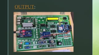
EMBEDDED SYSTEM LAB EXPERIMENT
3.
AIM:
To GenerateA Specific Time Delay Using
Timers In A Microcontroller
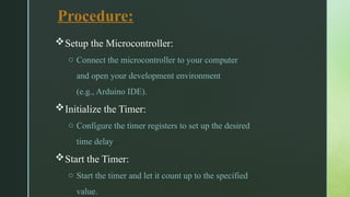
Procedure:
Setup the Microcontroller:
oConnect the microcontroller to your computer
and open your development environment
(e.g., Arduino IDE).
Initialize the Timer:
o Configure the timer registers to set up the desired
time delay.
Start the Timer:
o Start the timer and let it count up to the specified
value.
9.
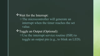
Wait for theInterrupt:
oThe microcontroller will generate an
interrupt when the timer reaches the set
value.
Toggle an Output (Optional):
oUse the interrupt service routine (ISR) to
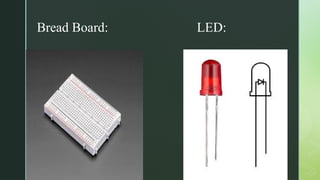
toggle an output pin (e.g., to blink an LED).
10.
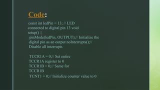
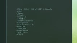
Code:
const int ledPin= 13; // LED
connected to digital pin 13 void
setup() {
pinMode(ledPin, OUTPUT);// Initialize the
digital pin as an output noInterrupts();//
Disable all interrupts
TCCR1A = 0;// Set entire
TCCR1A register to 0
TCCR1B = 0;// Same for
TCCR1B
TCNT1 = 0;// Initialize counter value to 0
interrupts(); // Enableall interrupts
}
ISR(TIMER1_COMPA_vect) {
// Timer1 interrupt service routine
digitalWrite(ledPin,
digitalRead(ledPin) ^ 1); // Toggle
the LED
}
void loop() {
// Nothing to do here, the ISR will handle everything
}
Result:
By configuringthe timer and enabling interrupts,
the microcontroller successfully generated the
desired time delay, which was used to toggle an
LED